2001 NISSAN PATROL ECO mode
[x] Cancel search: ECO modePage 2 of 273
FOREWORD
This manual contains maintenance and repair procedures for NISSAN
PATROL GR,modelY61 series.
In order to assure your safety and the efficient functioning of the vehicle,
this manual should be read thoroughly. It is especially important that the
PRECAUTIONS in the GI section be completely understood before starting
any repair task.
All information in this manual is based on the latest product information
at the time of publication. The right is reserved to make changes in speci-
®cations and methods at any time without notice.
IMPORTANT SAFETY NOTICE
The proper performance of service is essential for both the safety of the
technician and the efficient functioning of the vehicle.
The service methods in this Service Manual are described in such a man-
ner that the service may be performed safely and accurately.
Service varies with the procedures used, the skills of the technician and the
tools and parts available. Accordingly, anyone using service procedures,
tools or parts which are not speci®cally recommended by NISSAN must
®rst completely satisfy himself that neither his safety nor the vehicle's
safety will be jeopardized by the service method selected.
NISSAN EUROPE S.A.S.
Service Engineering SectionParis, France
Page 16 of 273
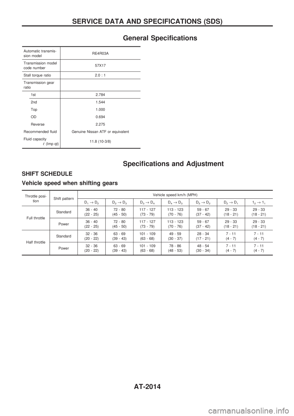
General Specifications
Automatic transmis-
sion modelRE4R03A
Transmission model
code number57X17
Stall torque ratio 2.0 : 1
Transmission gear
ratio
1st 2.784
2nd 1.544
Top 1.000
OD 0.694
Reverse 2.275
Recommended fluid Genuine Nissan ATF or equivalent
Fluid capacity
!(Imp qt)11.8 (10-3/8)
Specifications and Adjustment
SHIFT SCHEDULE
Vehicle speed when shifting gears
Throttle posi-
tionShift patternVehicle speed km/h (MPH)
D
1®D2D2®D3D3®D4D4®D3D3®D2D2®D112®11
Full throttleStandard36-40
(22 - 25)72-80
(45 - 50)117 - 127
(73 - 79)113 - 123
(70 - 76)59-67
(37 - 42)29-33
(18 - 21)29-33
(18 - 21)
Power36-40
(22 - 25)72-80
(45 - 50)117 - 127
(73 - 79)113 - 123
(70 - 76)59-67
(37 - 42)29-33
(18 - 21)29-33
(18 - 21)
Half throttleStandard32-36
(20 - 22)63-69
(39 - 43)101 - 109
(63 - 68)49-59
(30 - 37)28-34
(17 - 21)7-11
(4-7)7-11
(4-7)
Power32-36
(20 - 22)63-69
(39 - 43)101 - 109
(63 - 68)78-86
(48 - 53)48-54
(30 - 34)7-11
(4-7)7-11
(4-7)
SERVICE DATA AND SPECIFICATIONS (SDS)
AT-2014
Page 35 of 273
Clutch Cover
INSTALLATION
Model 300
+Apply recommended grease to contact surface of splines.
+Too much lubricant may damage clutch disc facing.
+Insert Tool into clutch disc hub when installing clutch cover
and disc.
+Be careful not to allow grease to contaminate clutch facing.
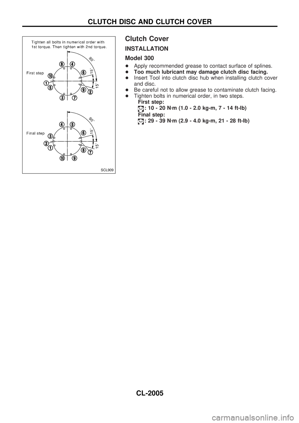
+Tighten bolts in numerical order, in two steps.
First step:
:10-20Nzm (1.0 - 2.0 kg-m,7-14ft-lb)
Final step:
:29-39Nzm (2.9 - 4.0 kg-m, 21 - 28 ft-lb)
SCL909
CLUTCH DISC AND CLUTCH COVER
CL-2005
Page 155 of 273
System Description
WIPER OPERATION
The rear wiper switch is controlled by a ring built into the combination switch.
There are two wiper switch positions:
+ON (LO speed)
+INT (Intermittent)
With the ignition switch in the ON position, power is supplied
+through 10A fuse (No.
18, located in the fuse block)
+to rear wiper motor terminal
V4, and
+to rear wiper amplifier terminal
V5.
Low speed wiper operation
Ground is supplied to rear wiper switch terminalV24through body grounds.
When the rear wiper is placed in the ON position, ground is supplied
+through rear wiper switch terminal
V22
+to rear wiper relay terminalV6.
Then ground is supplied
+to rear wiper motor terminal
V1
+through rear wiper amplifier terminalsV2andV3.
With power and ground supplied, the wiper motor operates.
Auto stop operation
With the rear wiper switch turned OFF, rear wiper motor will continue to operate until wiper arm reaches
rear window base.
When wiper arm is not located at base of rear window with rear wiper switch OFF, ground is supplied
+to rear wiper motor terminal
V1
+through rear wiper amplifier terminalsV2,V7and
+through rear wiper motor terminal
V3, in order to continue rear wiper motor operation at low speed.
Ground is also supplied
+to rear wiper motor terminal
V2
+through body grounds.
When wiper arm reaches base of rear window, rear wiper motor terminals
V3andV4are connected instead
of terminals
V2andV3. Rear wiper motor will then stop wiper arm at the PARK position.
Intermittent operation
The rear wiper motor operates the wiper arm one time at low speed at an interval of approximately 7 sec-
onds.
When the rear wiper switch is placed in the INT position, ground is supplied
+to rear wiper amplifier terminal
V1
+through rear wiper switch terminalV21.
Then the rear wiper motor operates intermittently in the same manner as the low speed wiper operation.
WASHER OPERATION
With the ignition switch in the ACC or ON position, power is supplied
+through 10A fuse (No.
18, located in the fuse block)
+to rear washer motor terminal
V2.
When the ring is turned WASH position, ground is supplied
+to rear washer motor terminal
V1, and
+to rear wiper amplifier terminal
V4
+through terminalV23of rear wiper switch.
With power and ground is supplied, the rear washer motor operates.
The rear wiper motor operates when the ring is turned to WASH position for one second or more and for
approximately 3 seconds after the ring is released. This feature is controlled by the rear wiper amplifier in
the same manner as the low speed wiper operation.
REAR WIPER AND WASHER/WAGON AND HARDTOP MODELS
EL-2078
Page 265 of 273
Trouble Diagnoses Introduction
CAUTION:
+Do not use electrical test equipment to check SRS harness connectors unless instructed to in
this Service Manual. SRS wiring harnesses can be identified by yellow harness connector.
+Do not attempt to repair, splice or modify the SRS wiring harness. If the harness is damaged,
replace it with a new one.
+Keep ground portion clean.
DIAGNOSIS FUNCTION
The SRS self-diagnosis results can be read by using ªAIR BAGº warning lamp and/or CONSULT-II. The
reading of these results is accomplished using one of two modes Ð ªUser modeº and ªDiagnosis modeº.
The User mode is exclusively prepared for the customer (driver). This mode warns the driver of a system
malfunction through the operation of the ªAIR BAGº warning lamp.
The Diagnosis mode allows the technician to locate and inspect the malfunctioning part.
The mode applications for the ªAIR BAGº warning lamp and CONSULT-II are as follows:
User mode Diagnosis mode Display type
ªAIR BAGº warning lamp X X ON-OFF operation
CONSULT-II Ð X Monitoring
DIAGNOSIS MODE FOR CONSULT-II
+ªSELF-DIAG [CURRENT]º
A current Self-diagnosis result (also indicated by the warning lamp flashes in the Diagnosis mode) is
displayed on the CONSULT-II screen in real time. This refers to a malfunctioning part requiring repairs.
+ªSELF-DIAG [PAST]º
Diagnosis results previously stored in the memory are displayed on the CONSULT-II screen. The stored
results are not erased until memory erasing is executed.
+ªTROUBLE DIAG RECORDº
With TROUBLE DIAG RECORD, diagnosis results previously erased by a reset operation can be dis-
played on the CONSULT-II screen.
+ªECU DISCRIMINATED NO.º
The diagnosis sensor unit for each vehicle model is assigned with its own, individual classification number.
This number will be displayed on the CONSULT-II screen, as shown at left. When replacing the diagnosis
sensor unit, refer to the part number for the compatibility. After installation, replacement with a correct unit
can be checked by confirming this classification number on the CONSULT-II screen. The diagnosis sensor
unit classification number varies depending on SRS configuration.
For NISSAN MODEL Y61, the diagnosis sensor unit classification numbers are as follows.
MODEL ECU DISCRIMINATED NO.
Model with dual air bags, side air bag and seat belt pre-tensioner 5A35
Model with dual air bags and side air bag 5A34
Model with dual air bags and seat belt pre-tensioner 5A33
Model with dual air bag5A32
Model with single air bag and pre-tensioner 5A31
Model with single air bag5A30
TROUBLE DIAGNOSES Ð Supplemental Restraint System (SRS)
RS-2014
Page 267 of 273
Without CONSULT-II
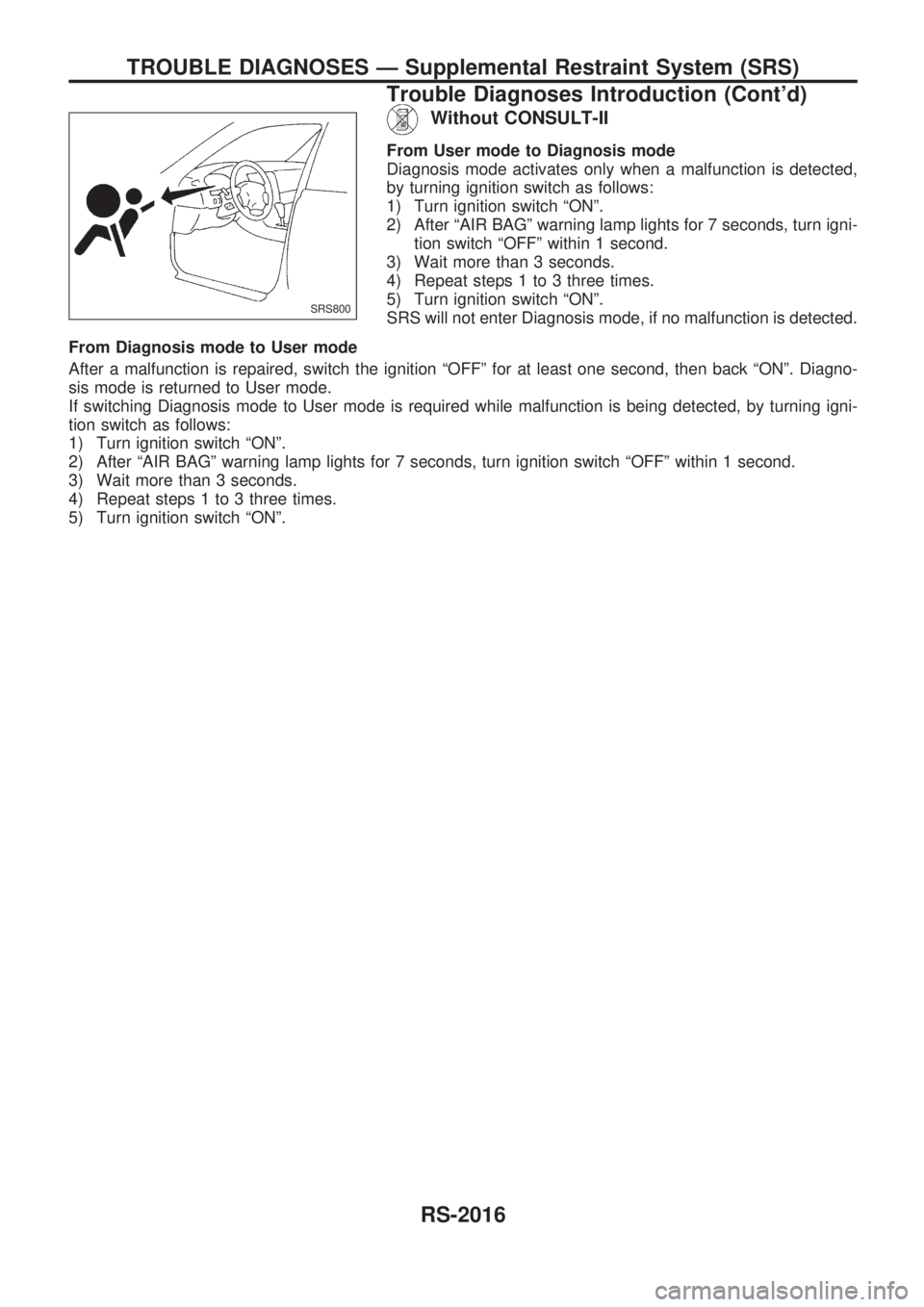
From User mode to Diagnosis mode
Diagnosis mode activates only when a malfunction is detected,
by turning ignition switch as follows:
1) Turn ignition switch ªONº.
2) After ªAIR BAGº warning lamp lights for 7 seconds, turn igni-
tion switch ªOFFº within 1 second.
3) Wait more than 3 seconds.
4) Repeat steps 1 to 3 three times.
5) Turn ignition switch ªONº.
SRS will not enter Diagnosis mode, if no malfunction is detected.
From Diagnosis mode to User mode
After a malfunction is repaired, switch the ignition ªOFFº for at least one second, then back ªONº. Diagno-
sis mode is returned to User mode.
If switching Diagnosis mode to User mode is required while malfunction is being detected, by turning igni-
tion switch as follows:
1) Turn ignition switch ªONº.
2) After ªAIR BAGº warning lamp lights for 7 seconds, turn ignition switch ªOFFº within 1 second.
3) Wait more than 3 seconds.
4) Repeat steps 1 to 3 three times.
5) Turn ignition switch ªONº.
SRS800
TROUBLE DIAGNOSES Ð Supplemental Restraint System (SRS)
Trouble Diagnoses Introduction (Cont'd)
RS-2016
Page 268 of 273
![NISSAN PATROL 2001 Electronic Repair Manual HOW TO ERASE SELF-DIAGNOSIS RESULTS
With CONSULT-II
+ªSELF-DIAG [CURRENT]º
A current Self-diagnosis result is displayed on the CON-
SULT-II screen in real time. After the malfunction is repaired
com NISSAN PATROL 2001 Electronic Repair Manual HOW TO ERASE SELF-DIAGNOSIS RESULTS
With CONSULT-II
+ªSELF-DIAG [CURRENT]º
A current Self-diagnosis result is displayed on the CON-
SULT-II screen in real time. After the malfunction is repaired
com](/manual-img/5/57366/w960_57366-267.png)
HOW TO ERASE SELF-DIAGNOSIS RESULTS
With CONSULT-II
+ªSELF-DIAG [CURRENT]º
A current Self-diagnosis result is displayed on the CON-
SULT-II screen in real time. After the malfunction is repaired
completely, no malfunction is detected on ªSELF-DIAG
[CURRENT]º.
+ªSELF-DIAG [PAST]º
Return to the ªSELF-DIAG [CURRENT]º CONSULT-II screen
by pushing ªBACKº key of CONSULT-II and select ªSELF-
DIAG [CURRENT]º in ªSELECT DIAG MODEº. Touch
ªERASEº in ªSELF-DIAG [CURRENT]º mode.
NOTE:
If the memory of the malfunction in ªSELF-DIAG [PAST]º is
not erased, the User mode shows the system malfunction by
the operation of the warning lamp even if the malfunction is
repaired completely.
+ªTROUBLE DIAG RECORDº
The memory of ªTROUBLE DIAG RECORDº cannot be
erased.
Without CONSULT-II
After a malfunction is repaired, return Diagnosis mode to User
mode by switching the ignition ªOFFº for at least 1 second, then
back ªONº. At that time, the self-diagnostic result is cleared.
How to Perform Trouble Diagnoses for Quick
and Accurate Repair
A good understanding of the malfunction conditions can make troubleshooting faster and more accurate.
In general, each customer feels differently about a malfunction. It is important to fully understand the symp-
toms or conditions for a customer complaint.
INFORMATION FROM CUSTOMER
WHAT ........ Vehicle model
WHEN ....... Date, Frequencies
WHERE ..... Road conditions
HOW .......... Operating conditions, Symptoms
PRELIMINARY CHECK
Check that the following parts are in good order.
+Battery [Refer to EL section (ªBATTERYº) of Service Manual.]
+Fuse [Refer to EL section (ªFuseº, ªPOWER SUPPLY ROUTINGº) of Service Manual.]
+System component-to-harness connections
SRS701
TROUBLE DIAGNOSES Ð Supplemental Restraint System (SRS)
Trouble Diagnoses Introduction (Cont'd)
RS-2017