2001 NISSAN PATROL window
[x] Cancel search: windowPage 78 of 273
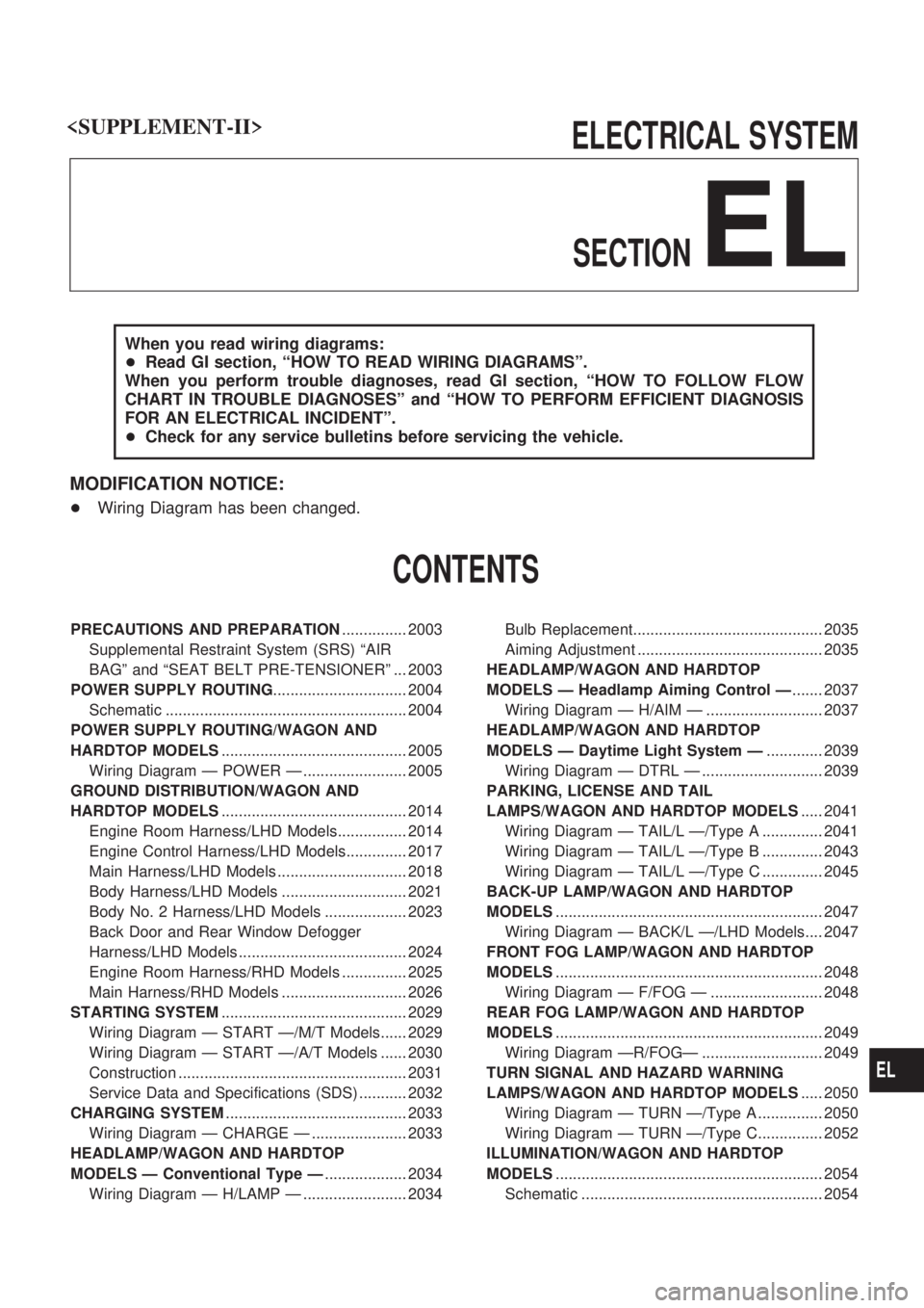
ELECTRICAL SYSTEM
SECTION
EL
When you read wiring diagrams:
+Read GI section, ªHOW TO READ WIRING DIAGRAMSº.
When you perform trouble diagnoses, read GI section, ªHOW TO FOLLOW FLOW
CHART IN TROUBLE DIAGNOSESº and ªHOW TO PERFORM EFFICIENT DIAGNOSIS
FOR AN ELECTRICAL INCIDENTº.
+Check for any service bulletins before servicing the vehicle.
MODIFICATION NOTICE:
+Wiring Diagram has been changed.
CONTENTS
PRECAUTIONS AND PREPARATION............... 2003
Supplemental Restraint System (SRS) ªAIR
BAGº and ªSEAT BELT PRE-TENSIONERº ... 2003
POWER SUPPLY ROUTING............................... 2004
Schematic ........................................................ 2004
POWER SUPPLY ROUTING/WAGON AND
HARDTOP MODELS........................................... 2005
Wiring Diagram Ð POWER Ð ........................ 2005
GROUND DISTRIBUTION/WAGON AND
HARDTOP MODELS........................................... 2014
Engine Room Harness/LHD Models................ 2014
Engine Control Harness/LHD Models.............. 2017
Main Harness/LHD Models .............................. 2018
Body Harness/LHD Models ............................. 2021
Body No. 2 Harness/LHD Models ................... 2023
Back Door and Rear Window Defogger
Harness/LHD Models ....................................... 2024
Engine Room Harness/RHD Models ............... 2025
Main Harness/RHD Models ............................. 2026
STARTING SYSTEM........................................... 2029
Wiring Diagram Ð START Ð/M/T Models...... 2029
Wiring Diagram Ð START Ð/A/T Models ...... 2030
Construction ..................................................... 2031
Service Data and Specifications (SDS) ........... 2032
CHARGING SYSTEM.......................................... 2033
Wiring Diagram Ð CHARGE Ð ...................... 2033
HEADLAMP/WAGON AND HARDTOP
MODELS Ð Conventional Type Ð................... 2034
Wiring Diagram Ð H/LAMP Ð ........................ 2034Bulb Replacement............................................ 2035
Aiming Adjustment ........................................... 2035
HEADLAMP/WAGON AND HARDTOP
MODELS Ð Headlamp Aiming Control Ð....... 2037
Wiring Diagram Ð H/AIM Ð ........................... 2037
HEADLAMP/WAGON AND HARDTOP
MODELS Ð Daytime Light System Ð............. 2039
Wiring Diagram Ð DTRL Ð ............................ 2039
PARKING, LICENSE AND TAIL
LAMPS/WAGON AND HARDTOP MODELS..... 2041
Wiring Diagram Ð TAIL/L Ð/Type A .............. 2041
Wiring Diagram Ð TAIL/L Ð/Type B .............. 2043
Wiring Diagram Ð TAIL/L Ð/Type C .............. 2045
BACK-UP LAMP/WAGON AND HARDTOP
MODELS.............................................................. 2047
Wiring Diagram Ð BACK/L Ð/LHD Models.... 2047
FRONT FOG LAMP/WAGON AND HARDTOP
MODELS.............................................................. 2048
Wiring Diagram Ð F/FOG Ð .......................... 2048
REAR FOG LAMP/WAGON AND HARDTOP
MODELS.............................................................. 2049
Wiring Diagram ÐR/FOGÐ ............................ 2049
TURN SIGNAL AND HAZARD WARNING
LAMPS/WAGON AND HARDTOP MODELS..... 2050
Wiring Diagram Ð TURN Ð/Type A ............... 2050
Wiring Diagram Ð TURN Ð/Type C............... 2052
ILLUMINATION/WAGON AND HARDTOP
MODELS.............................................................. 2054
Schematic ........................................................ 2054
EL
Page 79 of 273
Wiring Diagram Ð ILL Ð ................................ 2055
METER AND GAUGES/WAGON AND
HARDTOP MODELS ........................................... 2062
Combination Meter........................................... 2062
Schematic ........................................................ 2063
Wiring Diagram Ð METER Ð ......................... 2064
COMPASS AND THERMOMETER ..................... 2066
Wiring Diagram Ð COMPAS Ð ...................... 2066
WARNING LAMPS/WAGON AND HARDTOP
MODELS .............................................................. 2067
Schematic ........................................................ 2067
Wiring Diagram/Ð WARN Ð........................... 2069
WARNING CHIME/WAGON AND HARDTOP
MODELS .............................................................. 2077
Electrical Components Inspection ................... 2077
REAR WIPER AND WASHER/WAGON AND
HARDTOP MODELS ........................................... 2078
System Description .......................................... 2078
Wiring Diagram Ð WIP/R Ð/LHD Models ...... 2079
Wiring Diagram Ð WIP/R Ð/RHD Models ..... 2081
HEADLAMP WIPER AND WASHER .................. 2083
Wiring Diagram Ð HLC Ð .............................. 2083
HORN ................................................................... 2084
Wiring Diagram Ð HORN Ð ........................... 2084
CIGARETTE LIGHTER/WAGON AND
HARDTOP MODELS ........................................... 2085
Wiring Diagram Ð CIGAR Ð .......................... 2085
WIPER DEICER/WAGON AND HARDTOP
MODELS .............................................................. 2086
Wiring Diagram Ð DEICER Ð ........................ 2086
REAR WINDOW DEFOGGER/WAGON AND
HARDTOP MODELS ........................................... 2087
Electrical Components Inspection ................... 2087
AUDIO/WAGON AND HARDTOP MODELS ...... 2088
Wiring Diagram Ð AUDIO Ð/LHD Models ..... 2088
Wiring Diagram Ð AUDIO Ð/RHD Models .... 2090
Wiring Diagram Ð CD/CHG Ð/LHD Wagon .. 2092
Wiring Diagram Ð CD/CHG Ð/LHD
Hardtop ............................................................ 2093 Wiring Diagram Ð CD/CHG Ð/RHD
Hardtop ............................................................ 2094
Wiring Diagram Ð REMOTE Ð ...................... 2095
Wiring Diagram Ð P/ANT Ð/LHD Models ...... 2096
Wiring Diagram Ð P/ANT Ð/RHD Models ..... 2097
POWER DOOR MIRROR/WAGON AND
HARDTOP MODELS ........................................... 2098
Wiring Diagram Ð MIRROR Ð/LHD Models .. 2098
Wiring Diagram Ð MIRROR Ð/RHD Models . 2099
NATS (Nissan Anti-Theft System)/ZD ENGINE
MODELS .............................................................. 2100
Wiring Diagram Ð NATS Ð ............................ 2100
Wiring Diagram Ð NATS Ð/LHD Models ....... 2101
Wiring Diagram Ð NATS Ð/RHD Models ...... 2102
LOCATION OF ELECTRICAL UNITS/WAGON
AND HARDTOP MODELS .................................. 2103
Engine Compartment ....................................... 2103
Passenger Compartment Ð LHD Models ....... 2104
HARNESS LAYOUT ............................................ 2106
How to Read Harness Layout ......................... 2106
HARNESS LAYOUT/WAGON AND HARDTOP
MODELS .............................................................. 2108
Main Harness/LHD Models .............................. 2108
Main Harness/RHD Models ............................. 2112
Engine Room Harness/LHD Models................ 2116
Body Harness/LHD Models ............................. 2120
Body Harness/RHD Models ............................. 2124
Body No. 2 Harness/LHD Models ................... 2128
Body No. 2 Harness/RHD Models ................... 2130
WIRING DIAGRAM CODES (CELL CODES) ..... 2132
Wiring Diagram Codes (Cell Codes) ............... 2132
EL-2002
Page 101 of 273

Back Door and Rear Window Defogger
Harness/LHD Models
CEL222M
GROUND DISTRIBUTION/WAGON AND HARDTOP MODELS
EL-2024
Page 155 of 273
System Description
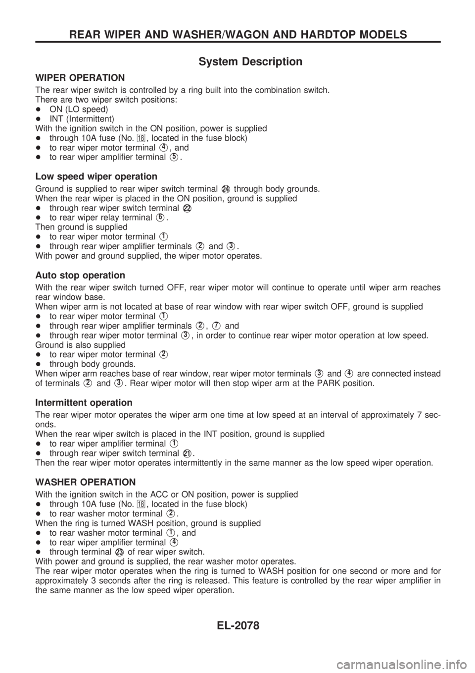
WIPER OPERATION
The rear wiper switch is controlled by a ring built into the combination switch.
There are two wiper switch positions:
+ON (LO speed)
+INT (Intermittent)
With the ignition switch in the ON position, power is supplied
+through 10A fuse (No.
18, located in the fuse block)
+to rear wiper motor terminal
V4, and
+to rear wiper amplifier terminal
V5.
Low speed wiper operation
Ground is supplied to rear wiper switch terminalV24through body grounds.
When the rear wiper is placed in the ON position, ground is supplied
+through rear wiper switch terminal
V22
+to rear wiper relay terminalV6.
Then ground is supplied
+to rear wiper motor terminal
V1
+through rear wiper amplifier terminalsV2andV3.
With power and ground supplied, the wiper motor operates.
Auto stop operation
With the rear wiper switch turned OFF, rear wiper motor will continue to operate until wiper arm reaches
rear window base.
When wiper arm is not located at base of rear window with rear wiper switch OFF, ground is supplied
+to rear wiper motor terminal
V1
+through rear wiper amplifier terminalsV2,V7and
+through rear wiper motor terminal
V3, in order to continue rear wiper motor operation at low speed.
Ground is also supplied
+to rear wiper motor terminal
V2
+through body grounds.
When wiper arm reaches base of rear window, rear wiper motor terminals
V3andV4are connected instead
of terminals
V2andV3. Rear wiper motor will then stop wiper arm at the PARK position.
Intermittent operation
The rear wiper motor operates the wiper arm one time at low speed at an interval of approximately 7 sec-
onds.
When the rear wiper switch is placed in the INT position, ground is supplied
+to rear wiper amplifier terminal
V1
+through rear wiper switch terminalV21.
Then the rear wiper motor operates intermittently in the same manner as the low speed wiper operation.
WASHER OPERATION
With the ignition switch in the ACC or ON position, power is supplied
+through 10A fuse (No.
18, located in the fuse block)
+to rear washer motor terminal
V2.
When the ring is turned WASH position, ground is supplied
+to rear washer motor terminal
V1, and
+to rear wiper amplifier terminal
V4
+through terminalV23of rear wiper switch.
With power and ground is supplied, the rear washer motor operates.
The rear wiper motor operates when the ring is turned to WASH position for one second or more and for
approximately 3 seconds after the ring is released. This feature is controlled by the rear wiper amplifier in
the same manner as the low speed wiper operation.
REAR WIPER AND WASHER/WAGON AND HARDTOP MODELS
EL-2078
Page 164 of 273
Electrical Components Inspection
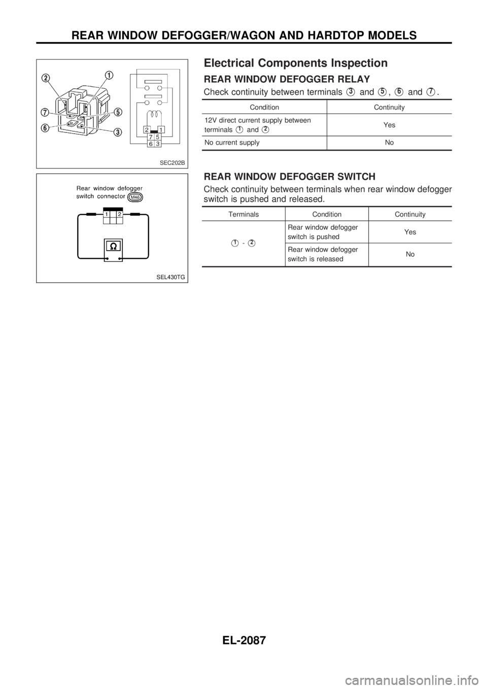
REAR WINDOW DEFOGGER RELAY
Check continuity between terminalsV3andV5,V6andV7.
Condition Continuity
12V direct current supply between
terminals
V1andV2Yes
No current supply No
REAR WINDOW DEFOGGER SWITCH
Check continuity between terminals when rear window defogger
switch is pushed and released.
Terminals Condition Continuity
V1-V2
Rear window defogger
switch is pushedYes
Rear window defogger
switch is releasedNo
SEC202B
SEL430TG
REAR WINDOW DEFOGGER/WAGON AND HARDTOP MODELS
EL-2087
Page 209 of 273
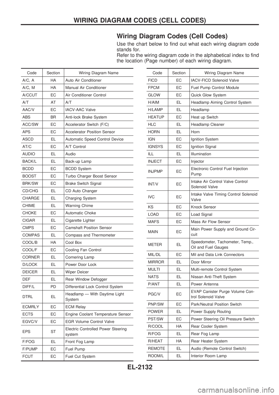
Wiring Diagram Codes (Cell Codes)
Use the chart below to find out what each wiring diagram code
stands for.
Refer to the wiring diagram code in the alphabetical index to find
the location (Page number) of each wiring diagram.
Code Section Wiring Diagram Name
A/C, A HA Auto Air Conditioner
A/C, M HA Manual Air Conditioner
A/CCUT EC Air Conditioner Control
A/T AT A/T
AAC/V EC IACV-AAC Valve
ABS BR Anti-lock Brake System
ACC/SW EC Accelerator Switch (F/C)
APS EC Accelerator Position Sensor
ASCD EL Automatic Speed Control Device
AT/C EC A/T Control
AUDIO EL Audio
BACK/L EL Back-up Lamp
BCDD EC BCDD System
BOOST EC Turbo Charger Boost Sensor
BRK/SW EC Brake Switch Signal
CD/CHG EL CD Auto Changer
CHARGE EL Charging System
CHIME EL Warning Chime
CHOKE EC Automatic Choke
CIGAR EL Cigarette Lighter
CMPS EC Camshaft Position Sensor
COMPAS EL Compass and Thermometer
COOL/B HA Cool Box
COOL/F EC Cooling Fan Control
CORNER EL Cornering Lamp
D/LOCK EL Power Door Lock
DEICER EL Wiper Deicer
DEF EL Rear Window Defogger
DIFF/L PD Differential Lock Control System
DTRL ELHeadlamp Ð With Daytime Light
System
ECMRLY EC ECM Relay
ECTS EC Engine Coolant Temperature Sensor
EGVC/V EC EGR Volume Control Valve
EPS STElectric Controlled Power Steering
system
F/FOG EL Front Fog Lamp
F/PUMP EC Fuel Pump
FCUT EC Fuel Cut SystemCode Section Wiring Diagram Name
FICD EC IACV-FICD Solenoid Valve
FPCM EC Fuel Pump Control Module
GLOW EC Quick Glow System
H/AIM EL Headlamp Aiming Control System
H/LAMP EL Headlamp
HEATUP EC Heat up Switch
HLC EL Headlamp Cleaner
HORN EL Horn
IGN EC Ignition System
IGNSYS EC Ignition Signal
ILL EL Illumination
INJECT EC Injector
INJPMP ECElectronic Control Fuel Injection
Pump
INT/V ECIntake Air Control Valve Control
Solenoid Valve
IVC ECIntake Valve Timing Control Solenoid
Valve
KS EC Knock Sensor
LOAD EC Load Signal
MAFS EC Mass Air Flow Sensor
MAIN ECMain Power Supply and Ground Cir-
cuit
METER ELSpeedometer, Tachometer, Temp.,
Oil and Fuel Gauges
MIL/DL EC Mil and Data Link Connectors
MIRROR EL Door Mirror
MULTI EL Multi-remote Control System
NATS EL Nissan Anti-Theft System
P/ANT EL Power Antenna
PGC/V ECEVAP Canister Purge Volume Con-
trol Solenoid Valve
PNP/SW EC Park/Neutral Position Switch
POWER EL Power Supply Routing
PST/SW EC Power Steering Oil Pressure Switch
R/COOL HA Rear Cooler System
R/FOG EL Rear Fog Lamp
R/HEAT HA Rear Heater System
REMOTE EL Audio (Remote Control Switch)
ROOM/L EL Interior Room Lamp
WIRING DIAGRAM CODES (CELL CODES)
EL-2132