Page 2 of 273

FOREWORD
This manual contains maintenance and repair procedures for NISSAN
PATROL GR,modelY61 series.
In order to assure your safety and the efficient functioning of the vehicle,
this manual should be read thoroughly. It is especially important that the
PRECAUTIONS in the GI section be completely understood before starting
any repair task.
All information in this manual is based on the latest product information
at the time of publication. The right is reserved to make changes in speci-
®cations and methods at any time without notice.
IMPORTANT SAFETY NOTICE
The proper performance of service is essential for both the safety of the
technician and the efficient functioning of the vehicle.
The service methods in this Service Manual are described in such a man-
ner that the service may be performed safely and accurately.
Service varies with the procedures used, the skills of the technician and the
tools and parts available. Accordingly, anyone using service procedures,
tools or parts which are not speci®cally recommended by NISSAN must
®rst completely satisfy himself that neither his safety nor the vehicle's
safety will be jeopardized by the service method selected.
NISSAN EUROPE S.A.S.
Service Engineering SectionParis, France
Page 3 of 273
AUTOMATIC TRANSMISSION
SECTION
AT
MODIFICATION NOTICE:
+Wiring diagrams have been changed.
+Service Data and Specifications (SDS) have been changed.
CONTENTS
OVERALL SYSTEM............................................ 2002
Circuit Diagram ................................................ 2002
Wiring Diagram Ð A/T Ð ................................ 2003
TROUBLE DIAGNOSES Ð A/T Shift Lock
System................................................................. 2013Wiring Diagram Ð SHIFT Ð ........................... 2013
SERVICE DATA AND SPECIFICATIONS
(SDS).................................................................... 2014
General Specifications ..................................... 2014
Specifications and Adjustment......................... 2014
AT
Page 16 of 273

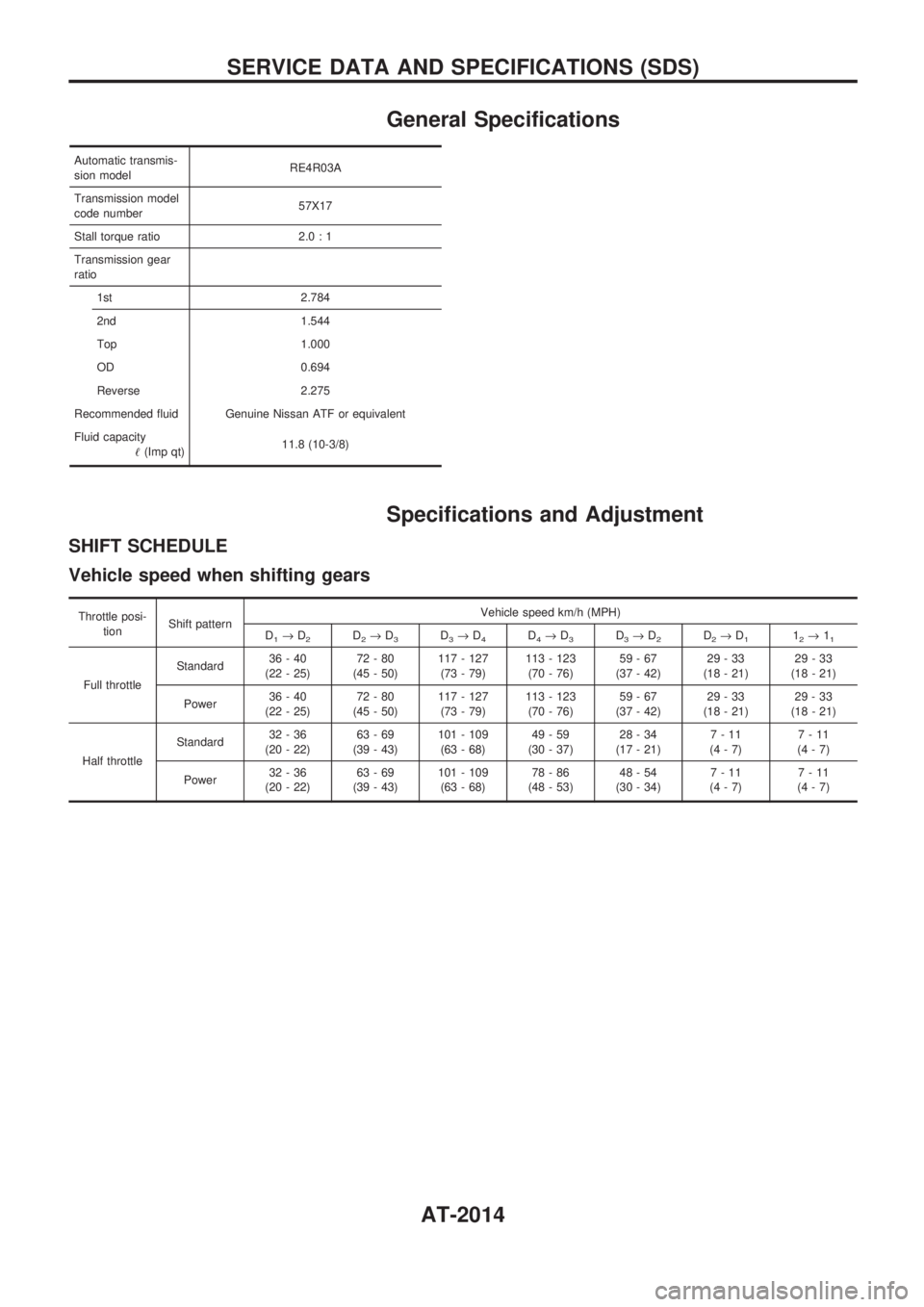
General Specifications
Automatic transmis-
sion modelRE4R03A
Transmission model
code number57X17
Stall torque ratio 2.0 : 1
Transmission gear
ratio
1st 2.784
2nd 1.544
Top 1.000
OD 0.694
Reverse 2.275
Recommended fluid Genuine Nissan ATF or equivalent
Fluid capacity
!(Imp qt)11.8 (10-3/8)
Specifications and Adjustment
SHIFT SCHEDULE
Vehicle speed when shifting gears
Throttle posi-
tionShift patternVehicle speed km/h (MPH)
D
1®D2D2®D3D3®D4D4®D3D3®D2D2®D112®11
Full throttleStandard36-40
(22 - 25)72-80
(45 - 50)117 - 127
(73 - 79)113 - 123
(70 - 76)59-67
(37 - 42)29-33
(18 - 21)29-33
(18 - 21)
Power36-40
(22 - 25)72-80
(45 - 50)117 - 127
(73 - 79)113 - 123
(70 - 76)59-67
(37 - 42)29-33
(18 - 21)29-33
(18 - 21)
Half throttleStandard32-36
(20 - 22)63-69
(39 - 43)101 - 109
(63 - 68)49-59
(30 - 37)28-34
(17 - 21)7-11
(4-7)7-11
(4-7)
Power32-36
(20 - 22)63-69
(39 - 43)101 - 109
(63 - 68)78-86
(48 - 53)48-54
(30 - 34)7-11
(4-7)7-11
(4-7)
SERVICE DATA AND SPECIFICATIONS (SDS)
AT-2014
Page 25 of 273
BODY & TRIM
SECTION
BT
MODIFICATION NOTICE:
+Front grille and bumper assembly have been changed.
+Front grille guard has been added.
CONTENTS
PRECAUTIONS................................................... 2002
Service Notice .................................................. 2002
Supplemental Restraint System (SRS) ªAIR
BAGº and ªSEAT BELT PRE-TENSIONERº ... 2002BODY END.......................................................... 2003
Body Front End ................................................ 2003
EXTERIOR........................................................... 2006
HFor seat belt, refer to MA and RS section.
HFor wiring diagrams of body electrical systems, refer to EL section.
BT
Page 26 of 273

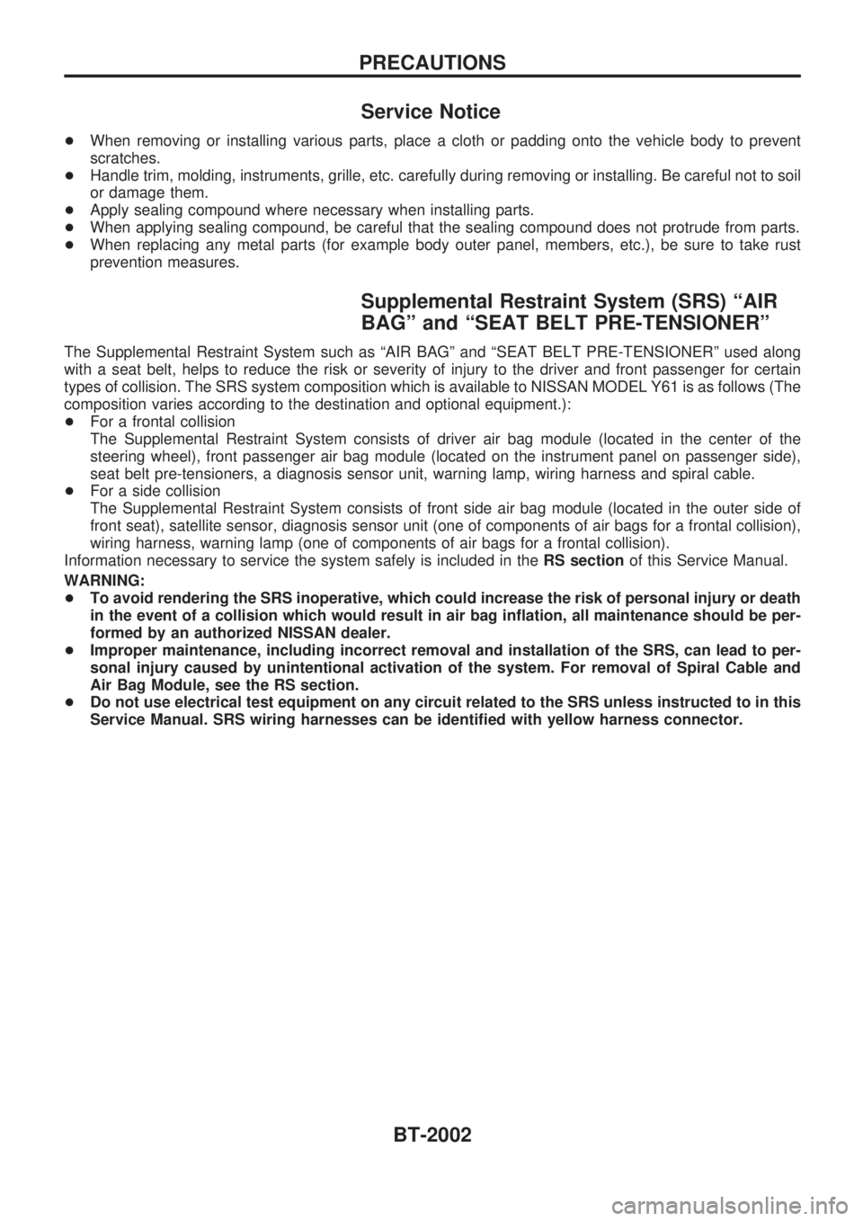
Service Notice
+When removing or installing various parts, place a cloth or padding onto the vehicle body to prevent
scratches.
+Handle trim, molding, instruments, grille, etc. carefully during removing or installing. Be careful not to soil
or damage them.
+Apply sealing compound where necessary when installing parts.
+When applying sealing compound, be careful that the sealing compound does not protrude from parts.
+When replacing any metal parts (for example body outer panel, members, etc.), be sure to take rust
prevention measures.
Supplemental Restraint System (SRS) ªAIR
BAGº and ªSEAT BELT PRE-TENSIONERº
The Supplemental Restraint System such as ªAIR BAGº and ªSEAT BELT PRE-TENSIONERº used along
with a seat belt, helps to reduce the risk or severity of injury to the driver and front passenger for certain
types of collision. The SRS system composition which is available to NISSAN MODEL Y61 is as follows (The
composition varies according to the destination and optional equipment.):
+For a frontal collision
The Supplemental Restraint System consists of driver air bag module (located in the center of the
steering wheel), front passenger air bag module (located on the instrument panel on passenger side),
seat belt pre-tensioners, a diagnosis sensor unit, warning lamp, wiring harness and spiral cable.
+For a side collision
The Supplemental Restraint System consists of front side air bag module (located in the outer side of
front seat), satellite sensor, diagnosis sensor unit (one of components of air bags for a frontal collision),
wiring harness, warning lamp (one of components of air bags for a frontal collision).
Information necessary to service the system safely is included in theRS sectionof this Service Manual.
WARNING:
+To avoid rendering the SRS inoperative, which could increase the risk of personal injury or death
in the event of a collision which would result in air bag inflation, all maintenance should be per-
formed by an authorized NISSAN dealer.
+Improper maintenance, including incorrect removal and installation of the SRS, can lead to per-
sonal injury caused by unintentional activation of the system. For removal of Spiral Cable and
Air Bag Module, see the RS section.
+Do not use electrical test equipment on any circuit related to the SRS unless instructed to in this
Service Manual. SRS wiring harnesses can be identified with yellow harness connector.
PRECAUTIONS
BT-2002
Page 31 of 273
CLUTCH
SECTION
CL
MODIFICATION NOTICE:
+Service Data and Specifications (SDS) have been changed.
CONTENTS
CLUTCH SYSTEM............................................... 2002
HYDRAULIC CLUTCH CONTROL..................... 2003
Clutch Operating Cylinder................................ 2003
Clutch Master Cylinder .................................... 2004
CLUTCH DISC AND CLUTCH COVER.............. 2005Clutch Cover .................................................... 2005
SERVICE DATA AND SPECIFICATIONS
(SDS).................................................................... 2006
General Specifications ..................................... 2006
Inspection and Adjustment .............................. 2006
CL
Page 36 of 273

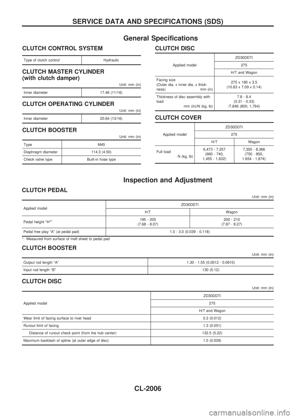
General Specifications
CLUTCH CONTROL SYSTEM
Type of clutch control Hydraulic
CLUTCH MASTER CYLINDER
(with clutch damper)
Unit: mm (in)
Inner diameter 17.46 (11/16)
CLUTCH OPERATING CYLINDER
Unit: mm (in)
Inner diameter 20.64 (13/16)
CLUTCH BOOSTER
Unit: mm (in)
Type M45
Diaphragm diameter 114.3 (4.50)
Check valve type Built-in hose type
CLUTCH DISC
Applied modelZD30DDTi
275
H/T and Wagon
Facing size
(Outer dia. x inner dia. x thick-
ness) mm (in)275 x 180 x 3.5
(10.83 x 7.09 x 0.14)
Thickness of disc assembly with
load
mm (in)/N (kg, lb)7.8 - 8.4
(0.31 - 0.33)
/7,846 (800, 1,764)
CLUTCH COVER
Applied modelZD30DDTi
275
H/T Wagon
Full load
N (kg, lb)6,473 - 7,257
(660 - 740,
1,455 - 1,632)7,355 - 8,366
(750 - 850,
1.654 - 1,874)
Inspection and Adjustment
CLUTCH PEDAL
Unit: mm (in)
Applied modelZD30DDTi
H/T Wagon
Pedal height ªH*º195 - 205
(7.68 - 8.07)200 - 210
(7.87 - 8.27)
Pedal free play ªAº (at pedal pad) 1.0 - 3.0 (0.039 - 0.118)
*: Measured from surface of melt sheet to pedal pad
CLUTCH BOOSTER
Unit: mm (in)
Output rod length ªAº1.30 - 1.55 (0.0512 - 0.0610)
Input rod length ªBº130 (5.12)
CLUTCH DISC
Unit: mm (in)
Applied modelZD30DDTi
275
H/T and Wagon
Wear limit of facing surface to rivet head 0.3 (0.012)
Runout limit of facing1.3 (0.051)
Distance of runout check point (from the hub center) 132.5 (5.22)
Maximum backlash of spline (at outer edge of disc) 1.0 (0.039)
SERVICE DATA AND SPECIFICATIONS (SDS)
CL-2006
Page 37 of 273
CLUTCH COVER
Unit: mm (in)
Applied modelZD30DDTi
275
H/T and Wagon
Diaphragm spring height ªAº44 - 46 (1.732 - 1.811)
Uneven limit of diaphragm spring toe height 0.7 (0.028)
SERVICE DATA AND SPECIFICATIONS (SDS)
CL-2007