2001 NISSAN PATROL service
[x] Cancel search: servicePage 78 of 273
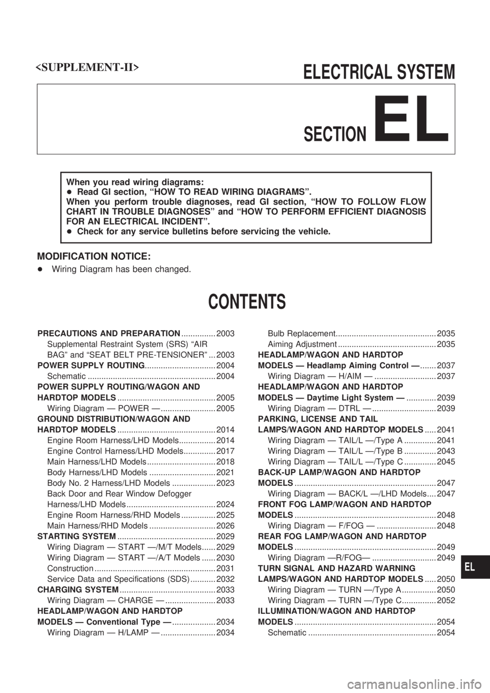
ELECTRICAL SYSTEM
SECTION
EL
When you read wiring diagrams:
+Read GI section, ªHOW TO READ WIRING DIAGRAMSº.
When you perform trouble diagnoses, read GI section, ªHOW TO FOLLOW FLOW
CHART IN TROUBLE DIAGNOSESº and ªHOW TO PERFORM EFFICIENT DIAGNOSIS
FOR AN ELECTRICAL INCIDENTº.
+Check for any service bulletins before servicing the vehicle.
MODIFICATION NOTICE:
+Wiring Diagram has been changed.
CONTENTS
PRECAUTIONS AND PREPARATION............... 2003
Supplemental Restraint System (SRS) ªAIR
BAGº and ªSEAT BELT PRE-TENSIONERº ... 2003
POWER SUPPLY ROUTING............................... 2004
Schematic ........................................................ 2004
POWER SUPPLY ROUTING/WAGON AND
HARDTOP MODELS........................................... 2005
Wiring Diagram Ð POWER Ð ........................ 2005
GROUND DISTRIBUTION/WAGON AND
HARDTOP MODELS........................................... 2014
Engine Room Harness/LHD Models................ 2014
Engine Control Harness/LHD Models.............. 2017
Main Harness/LHD Models .............................. 2018
Body Harness/LHD Models ............................. 2021
Body No. 2 Harness/LHD Models ................... 2023
Back Door and Rear Window Defogger
Harness/LHD Models ....................................... 2024
Engine Room Harness/RHD Models ............... 2025
Main Harness/RHD Models ............................. 2026
STARTING SYSTEM........................................... 2029
Wiring Diagram Ð START Ð/M/T Models...... 2029
Wiring Diagram Ð START Ð/A/T Models ...... 2030
Construction ..................................................... 2031
Service Data and Specifications (SDS) ........... 2032
CHARGING SYSTEM.......................................... 2033
Wiring Diagram Ð CHARGE Ð ...................... 2033
HEADLAMP/WAGON AND HARDTOP
MODELS Ð Conventional Type Ð................... 2034
Wiring Diagram Ð H/LAMP Ð ........................ 2034Bulb Replacement............................................ 2035
Aiming Adjustment ........................................... 2035
HEADLAMP/WAGON AND HARDTOP
MODELS Ð Headlamp Aiming Control Ð....... 2037
Wiring Diagram Ð H/AIM Ð ........................... 2037
HEADLAMP/WAGON AND HARDTOP
MODELS Ð Daytime Light System Ð............. 2039
Wiring Diagram Ð DTRL Ð ............................ 2039
PARKING, LICENSE AND TAIL
LAMPS/WAGON AND HARDTOP MODELS..... 2041
Wiring Diagram Ð TAIL/L Ð/Type A .............. 2041
Wiring Diagram Ð TAIL/L Ð/Type B .............. 2043
Wiring Diagram Ð TAIL/L Ð/Type C .............. 2045
BACK-UP LAMP/WAGON AND HARDTOP
MODELS.............................................................. 2047
Wiring Diagram Ð BACK/L Ð/LHD Models.... 2047
FRONT FOG LAMP/WAGON AND HARDTOP
MODELS.............................................................. 2048
Wiring Diagram Ð F/FOG Ð .......................... 2048
REAR FOG LAMP/WAGON AND HARDTOP
MODELS.............................................................. 2049
Wiring Diagram ÐR/FOGÐ ............................ 2049
TURN SIGNAL AND HAZARD WARNING
LAMPS/WAGON AND HARDTOP MODELS..... 2050
Wiring Diagram Ð TURN Ð/Type A ............... 2050
Wiring Diagram Ð TURN Ð/Type C............... 2052
ILLUMINATION/WAGON AND HARDTOP
MODELS.............................................................. 2054
Schematic ........................................................ 2054
EL
Page 80 of 273
Supplemental Restraint System (SRS) ªAIR
BAGº and ªSEAT BELT PRE-TENSIONERº
The Supplemental Restraint System such as ªAIR BAGº and ªSEAT BELT PRE-TENSIONERº used along
with a seat belt, helps to reduce the risk or severity of injury to the driver and front passenger for certain
types of collision. The SRS system composition which is available to NISSAN MODEL Y61 is as follows (The
composition varies according to the destination and optional equipment.):
+For a frontal collision
The Supplemental Restraint System consists of driver air bag module (located in the center of the
steering wheel), front passenger air bag module (located on the instrument panel on passenger side),
seat belt pre-tensioners, a diagnosis sensor unit, warning lamp, wiring harness and spiral cable.
+For a side collision
The Supplemental Restraint System consists of front side air bag module (located in the outer side of
front seat), satellite sensor, diagnosis sensor unit (one of components of air bags for a frontal collision),
wiring harness, warning lamp (one of components of air bags for a frontal collision).
Information necessary to service the system safely is included in theRS sectionof this Service Manual.
WARNING:
+To avoid rendering the SRS inoperative, which could increase the risk of personal injury or death
in the event of a collision which would result in air bag inflation, all maintenance should be per-
formed by an authorized NISSAN dealer.
+Improper maintenance, including incorrect removal and installation of the SRS, can lead to per-
sonal injury caused by intentional activation of the system. For removal of Spiral Cable and Air
Bag Module, see the RS section.
+Do not use electrical test equipment on any circuit related to the SRS unless instructed to in this
Service Manual. SRS wiring harnesses can be identified by yellow harness connector.
PRECAUTIONS AND PREPARATION
EL-2003
Page 109 of 273
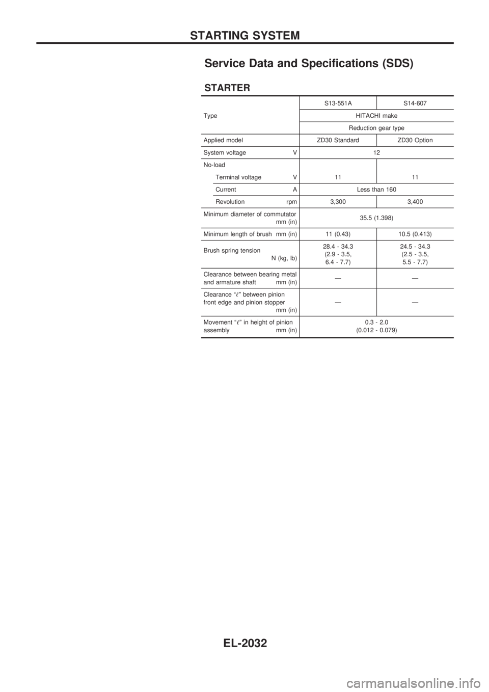
Service Data and Specifications (SDS)
STARTER
TypeS13-551A S14-607
HITACHI make
Reduction gear type
Applied model ZD30 Standard ZD30 Option
System voltage V 12
No-load
Terminal voltage V 11 11
Current A Less than 160
Revolution rpm 3,300 3,400
Minimum diameter of commutator
mm (in)35.5 (1.398)
Minimum length of brush mm (in) 11 (0.43) 10.5 (0.413)
Brush spring tension
N (kg, lb)28.4 - 34.3
(2.9 - 3.5,
6.4 - 7.7)24.5 - 34.3
(2.5 - 3.5,
5.5 - 7.7)
Clearance between bearing metal
and armature shaft mm (in)ÐÐ
Clearance ª!º between pinion
front edge and pinion stopper
mm (in)ÐÐ
Movement ª!º in height of pinion
assembly mm (in)0.3 - 2.0
(0.012 - 0.079)
STARTING SYSTEM
EL-2032
Page 221 of 273
Supplemental Restraint System (SRS) ªAIR
BAGº and ªSEAT BELT PRE-TENSIONERº
The Supplemental Restraint System such as ªAIR BAGº and ªSEAT BELT PRE-TENSIONERº used along
with a seat belt, helps to reduce the risk or severity of injury to the driver and front passenger for certain
types of collision. The SRS system composition which is available to NISSAN MODEL Y61 is as follows (The
composition varies according to the destination and optional equipment.):
+For a frontal collision
The Supplemental Restraint System consists of driver air bag module (located in the center of the
steering wheel), front passenger air bag module (located on the instrument panel on passenger side),
seat belt pre-tensioners, a diagnosis sensor unit, warning lamp, wiring harness and spiral cable.
+For a side collision
The Supplemental Restraint System consists of front side air bag module (located in the outer side of
front seat), satellite sensor, diagnosis sensor unit (one of components of air bags for a frontal collision),
wiring harness, warning lamp (one of components of air bags for a frontal collision).
Information necessary to service the system safely is included in theRS sectionof this Service Manual.
WARNING:
+To avoid rendering the SRS inoperative, which could increase the risk of personal injury or death
in the event of a collision which would result in air bag inflation, all maintenance should be per-
formed by an authorized NISSAN dealer.
+Improper maintenance, including incorrect removal and installation of the SRS, can lead to per-
sonal injury caused by unintentional activation of the system. For removal of Spiral Cable and
Air Bag Module, see the RS section.
+Do not use electrical test equipment on any circuit related to the SRS unless instructed to in this
Service Manual. Spiral cable and wiring harnesses covered with yellow insulation tape either just
before the harness connectors or for the complete harness are related to the SRS.
PRECAUTIONS AND PREPARATION
HA-2002
Page 252 of 273
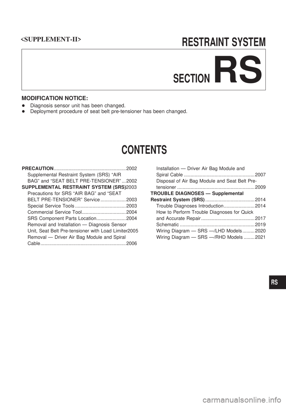
RESTRAINT SYSTEM
SECTION
RS
MODIFICATION NOTICE:
+Diagnosis sensor unit has been changed.
+Deployment procedure of seat belt pre-tensioner has been changed.
CONTENTS
PRECAUTION...................................................... 2002
Supplemental Restraint System (SRS) ªAIR
BAGº and ªSEAT BELT PRE-TENSIONERº ... 2002
SUPPLEMENTAL RESTRAINT SYSTEM (SRS)2003
Precautions for SRS ªAIR BAGº and ªSEAT
BELT PRE-TENSIONERº Service ................... 2003
Special Service Tools ...................................... 2003
Commercial Service Tool................................. 2004
SRS Component Parts Location...................... 2004
Removal and Installation Ð Diagnosis Sensor
Unit, Seat Belt Pre-tensioner with Load Limiter2005
Removal Ð Driver Air Bag Module and Spiral
Cable ................................................................ 2006Installation Ð Driver Air Bag Module and
Spiral Cable ..................................................... 2007
Disposal of Air Bag Module and Seat Belt Pre-
tensioner .......................................................... 2009
TROUBLE DIAGNOSES Ð Supplemental
Restraint System (SRS)..................................... 2014
Trouble Diagnoses Introduction ....................... 2014
How to Perform Trouble Diagnoses for Quick
and Accurate Repair ........................................ 2017
Schematic ........................................................ 2019
Wiring Diagram Ð SRS Ð/LHD Models ......... 2020
Wiring Diagram Ð SRS Ð/RHD Models ........ 2021
RS
Page 253 of 273
Supplemental Restraint System (SRS) ªAIR
BAGº and ªSEAT BELT PRE-TENSIONERº
The Supplemental Restraint System such as ªAIR BAGº and ªSEAT BELT PRE-TENSIONERº used along
with a seat belt, helps to reduce the risk or severity of injury to the driver and front passenger for certain
types of collision. The SRS composition which is available to NISSAN MODEL Y61 is as follows (The com-
position varies according to the destination and optional equipment.):
+For a frontal collision
The Supplemental Restraint System consists of driver air bag module (located in the center of the
steering wheel), front passenger air bag module (located on the instrument panel on passenger side),
seat belt pre-tensioners, a diagnosis sensor unit, warning lamp, wiring harness and spiral cable.
+For a side collision
The Supplemental Restraint System consists of front side air bag module (located in the outer side of
front seat), satellite sensor, diagnosis sensor unit (one of components of air bags for a frontal collision),
wiring harness, warning lamp (one of components of air bags for a frontal collision).
WARNING:
+To avoid rendering the SRS inoperative, which could increase the risk of personal injury or death
in the event of a collision which would result in air bag inflation, all maintenance should be per-
formed by an authorized NISSAN dealer.
+Improper maintenance, including incorrect removal and installation of the SRS, can lead to per-
sonal injury caused by unintentional activation of the system.
+Do not use electrical test equipment on any circuit related to the SRS unless instructed to in this
Service Manual. SRS wiring harnesses can be identified by yellow harness connector.
PRECAUTION
RS-2002
Page 254 of 273
Precautions for SRS ªAIR BAGº and ªSEAT
BELT PRE-TENSIONERº Service
+Do not use electrical test equipment to check SRS circuits unless instructed to in this Service Manual.
+Before servicing the SRS, turn ignition switch ªOFFº, disconnect both battery cables and wait at least 3
minutes.
For approximately 3 minutes after the cables are removed, it is still possible for the air bag and seat belt
pre-tensioner to deploy. Therefore, do not work on any SRS connectors or wires until at least 3 minutes
have passed.
+Diagnosis sensor unit must always be installed with their arrow marks ª
Sº pointing towards the front of
the vehicle for proper operation. Also check diagnosis sensor unit for cracks, deformities or rust before
installation and replace as required.
+The spiral cable must be aligned with the neutral position since its rotations are limited. Do not attempt
to turn steering wheel or column after removal of steering gear.
+Handle air bag module carefully. Always place driver and passenger air bag modules with the pad side
facing upward and front side air bag modules (built-in type) with the stud bolt side facing down.
+Conduct self-diagnosis to check entire SRS for proper function after replacing any components.
+After air bag inflates, the front instrument panel assembly should be replaced if damaged.
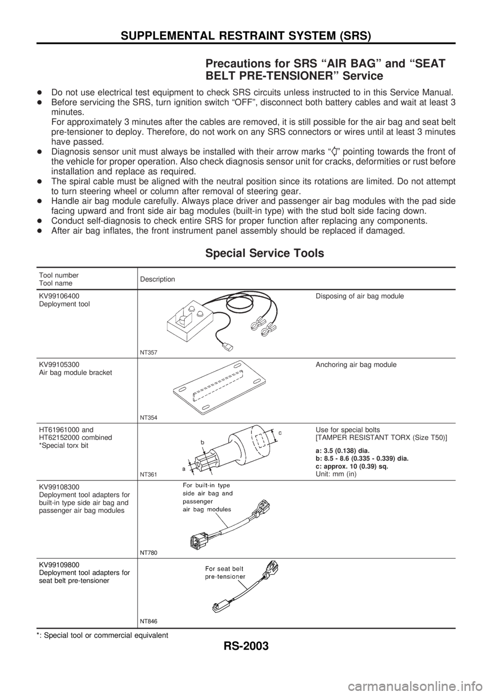
Special Service Tools
Tool number
Tool nameDescription
KV99106400
Deployment tool
NT357
Disposing of air bag module
KV99105300
Air bag module bracket
NT354
Anchoring air bag module
HT61961000 and
HT62152000 combined
*Special torx bit
NT361
Use for special bolts
[TAMPER RESISTANT TORX (Size T50)]
a: 3.5 (0.138) dia.
b: 8.5 - 8.6 (0.335 - 0.339) dia.
c: approx. 10 (0.39) sq.
Unit: mm (in)
KV99108300
Deployment tool adapters for
built-in type side air bag and
passenger air bag modules
NT780
KV99109800
Deployment tool adapters for
seat belt pre-tensioner
NT846
*: Special tool or commercial equivalent
SUPPLEMENTAL RESTRAINT SYSTEM (SRS)
RS-2003
Page 255 of 273
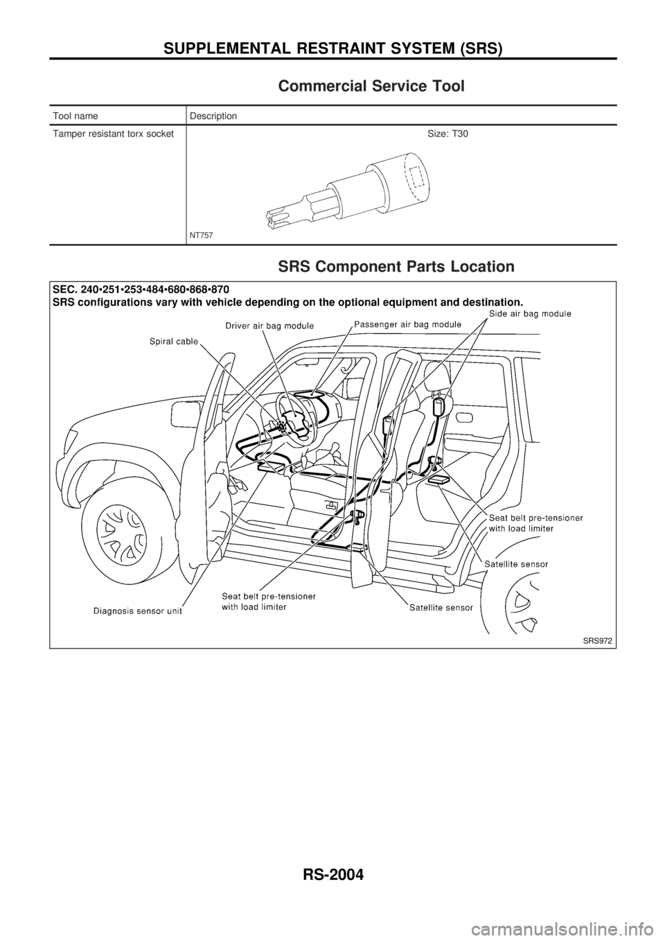
Commercial Service Tool
Tool name Description
Tamper resistant torx socket
NT757
Size: T30
SRS Component Parts Location
SRS972
SUPPLEMENTAL RESTRAINT SYSTEM (SRS)
RS-2004