2001 NISSAN PATROL sensor
[x] Cancel search: sensorPage 26 of 273
Service Notice
+When removing or installing various parts, place a cloth or padding onto the vehicle body to prevent
scratches.
+Handle trim, molding, instruments, grille, etc. carefully during removing or installing. Be careful not to soil
or damage them.
+Apply sealing compound where necessary when installing parts.
+When applying sealing compound, be careful that the sealing compound does not protrude from parts.
+When replacing any metal parts (for example body outer panel, members, etc.), be sure to take rust
prevention measures.
Supplemental Restraint System (SRS) ªAIR
BAGº and ªSEAT BELT PRE-TENSIONERº
The Supplemental Restraint System such as ªAIR BAGº and ªSEAT BELT PRE-TENSIONERº used along
with a seat belt, helps to reduce the risk or severity of injury to the driver and front passenger for certain
types of collision. The SRS system composition which is available to NISSAN MODEL Y61 is as follows (The
composition varies according to the destination and optional equipment.):
+For a frontal collision
The Supplemental Restraint System consists of driver air bag module (located in the center of the
steering wheel), front passenger air bag module (located on the instrument panel on passenger side),
seat belt pre-tensioners, a diagnosis sensor unit, warning lamp, wiring harness and spiral cable.
+For a side collision
The Supplemental Restraint System consists of front side air bag module (located in the outer side of
front seat), satellite sensor, diagnosis sensor unit (one of components of air bags for a frontal collision),
wiring harness, warning lamp (one of components of air bags for a frontal collision).
Information necessary to service the system safely is included in theRS sectionof this Service Manual.
WARNING:
+To avoid rendering the SRS inoperative, which could increase the risk of personal injury or death
in the event of a collision which would result in air bag inflation, all maintenance should be per-
formed by an authorized NISSAN dealer.
+Improper maintenance, including incorrect removal and installation of the SRS, can lead to per-
sonal injury caused by unintentional activation of the system. For removal of Spiral Cable and
Air Bag Module, see the RS section.
+Do not use electrical test equipment on any circuit related to the SRS unless instructed to in this
Service Manual. SRS wiring harnesses can be identified with yellow harness connector.
PRECAUTIONS
BT-2002
Page 38 of 273
ENGINE CONTROL SYSTEM
SECTION
EC
CONTENTS
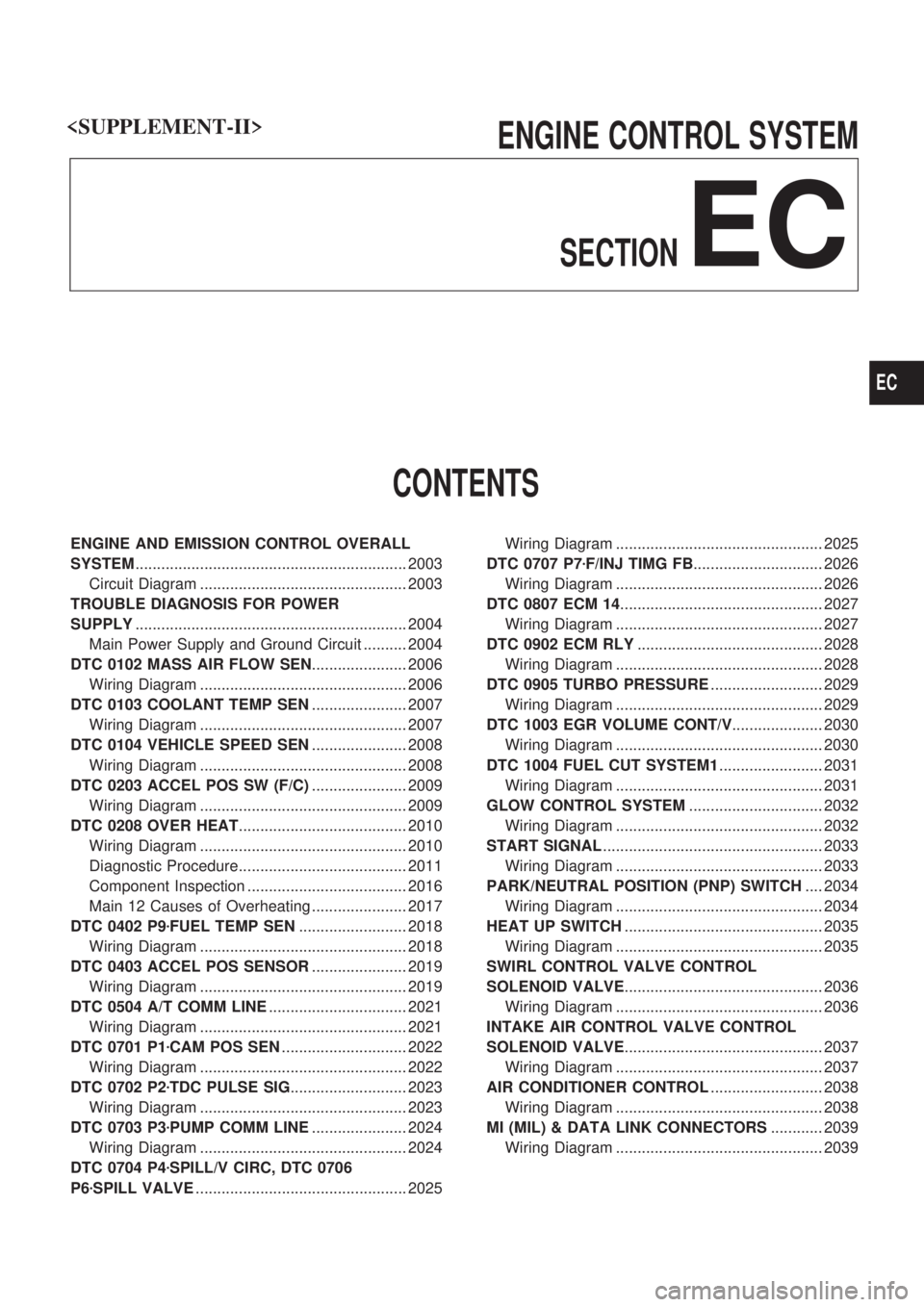
ENGINE AND EMISSION CONTROL OVERALL
SYSTEM............................................................... 2003
Circuit Diagram ................................................ 2003
TROUBLE DIAGNOSIS FOR POWER
SUPPLY............................................................... 2004
Main Power Supply and Ground Circuit .......... 2004
DTC 0102 MASS AIR FLOW SEN...................... 2006
Wiring Diagram ................................................ 2006
DTC 0103 COOLANT TEMP SEN...................... 2007
Wiring Diagram ................................................ 2007
DTC 0104 VEHICLE SPEED SEN...................... 2008
Wiring Diagram ................................................ 2008
DTC 0203 ACCEL POS SW (F/C)...................... 2009
Wiring Diagram ................................................ 2009
DTC 0208 OVER HEAT....................................... 2010
Wiring Diagram ................................................ 2010
Diagnostic Procedure....................................... 2011
Component Inspection ..................................... 2016
Main 12 Causes of Overheating ...................... 2017
DTC 0402 P9zFUEL TEMP SEN......................... 2018
Wiring Diagram ................................................ 2018
DTC 0403 ACCEL POS SENSOR...................... 2019
Wiring Diagram ................................................ 2019
DTC 0504 A/T COMM LINE................................ 2021
Wiring Diagram ................................................ 2021
DTC 0701 P1zCAM POS SEN............................. 2022
Wiring Diagram ................................................ 2022
DTC 0702 P2zTDC PULSE SIG........................... 2023
Wiring Diagram ................................................ 2023
DTC 0703 P3zPUMP COMM LINE...................... 2024
Wiring Diagram ................................................ 2024
DTC 0704 P4zSPILL/V CIRC, DTC 0706
P6zSPILL VALVE................................................. 2025Wiring Diagram ................................................ 2025
DTC 0707 P7zF/INJ TIMG FB.............................. 2026
Wiring Diagram ................................................ 2026
DTC 0807 ECM 14............................................... 2027
Wiring Diagram ................................................ 2027
DTC 0902 ECM RLY........................................... 2028
Wiring Diagram ................................................ 2028
DTC 0905 TURBO PRESSURE.......................... 2029
Wiring Diagram ................................................ 2029
DTC 1003 EGR VOLUME CONT/V..................... 2030
Wiring Diagram ................................................ 2030
DTC 1004 FUEL CUT SYSTEM1........................ 2031
Wiring Diagram ................................................ 2031
GLOW CONTROL SYSTEM............................... 2032
Wiring Diagram ................................................ 2032
START SIGNAL................................................... 2033
Wiring Diagram ................................................ 2033
PARK/NEUTRAL POSITION (PNP) SWITCH.... 2034
Wiring Diagram ................................................ 2034
HEAT UP SWITCH.............................................. 2035
Wiring Diagram ................................................ 2035
SWIRL CONTROL VALVE CONTROL
SOLENOID VALVE.............................................. 2036
Wiring Diagram ................................................ 2036
INTAKE AIR CONTROL VALVE CONTROL
SOLENOID VALVE.............................................. 2037
Wiring Diagram ................................................ 2037
AIR CONDITIONER CONTROL.......................... 2038
Wiring Diagram ................................................ 2038
MI (MIL) & DATA LINK CONNECTORS............ 2039
Wiring Diagram ................................................ 2039
EC
Page 48 of 273
Diagnostic Procedure
1 INSPECTION START
Do you have CONSULT-II?
Yes or No
YescGO TO 2.
NocGO TO 3.
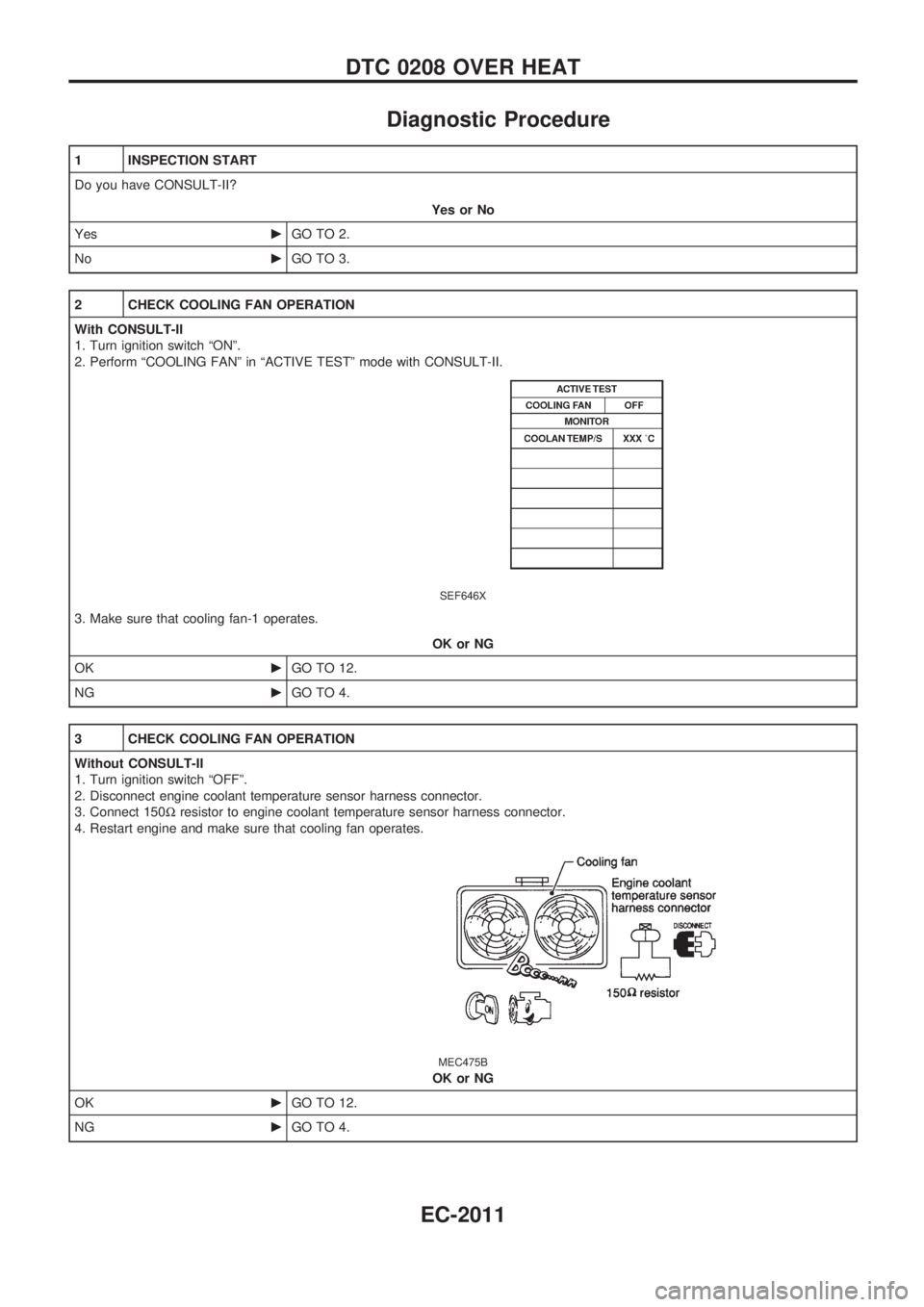
2 CHECK COOLING FAN OPERATION
With CONSULT-II
1. Turn ignition switch ªONº.
2. Perform ªCOOLING FANº in ªACTIVE TESTº mode with CONSULT-II.
SEF646X
3. Make sure that cooling fan-1 operates.
OK or NG
OKcGO TO 12.
NGcGO TO 4.
3 CHECK COOLING FAN OPERATION
Without CONSULT-II
1. Turn ignition switch ªOFFº.
2. Disconnect engine coolant temperature sensor harness connector.
3. Connect 150Wresistor to engine coolant temperature sensor harness connector.
4. Restart engine and make sure that cooling fan operates.
MEC475B
OK or NG
OKcGO TO 12.
NGcGO TO 4.
DTC 0208 OVER HEAT
EC-2011
Page 53 of 273
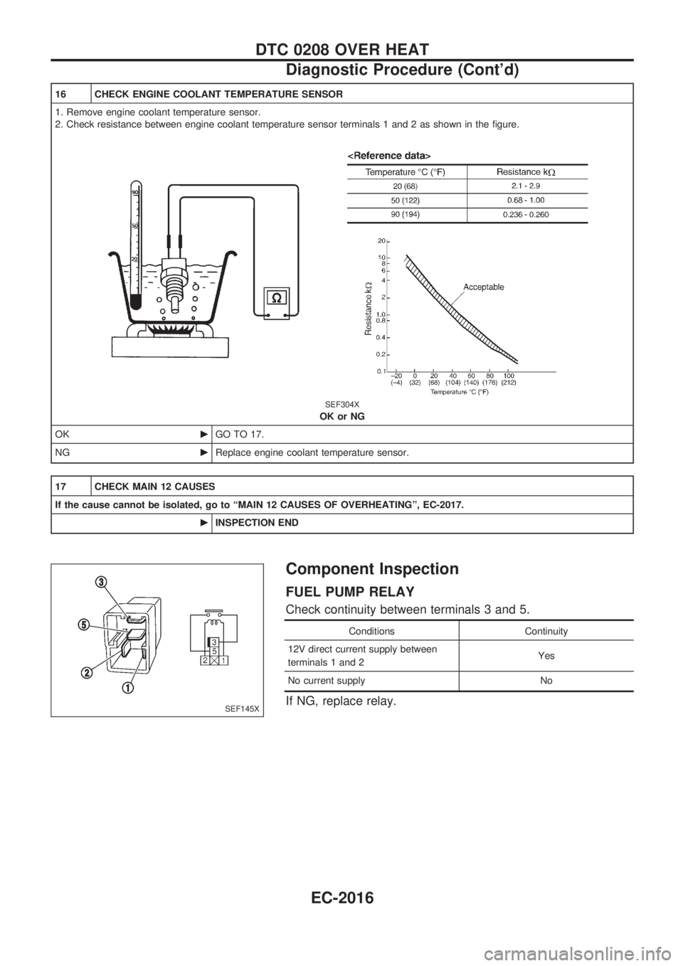
16 CHECK ENGINE COOLANT TEMPERATURE SENSOR
1. Remove engine coolant temperature sensor.
2. Check resistance between engine coolant temperature sensor terminals 1 and 2 as shown in the figure.
SEF304X
OK or NG
OKcGO TO 17.
NGcReplace engine coolant temperature sensor.
17 CHECK MAIN 12 CAUSES
If the cause cannot be isolated, go to ªMAIN 12 CAUSES OF OVERHEATINGº, EC-2017.
cINSPECTION END
Component Inspection
FUEL PUMP RELAY
Check continuity between terminals 3 and 5.
Conditions Continuity
12V direct current supply between
terminals 1 and 2Yes
No current supply No
If NG, replace relay.SEF145X
DTC 0208 OVER HEAT
Diagnostic Procedure (Cont'd)
EC-2016
Page 56 of 273

Wiring Diagram
TEC188M
DTC 0403 ACCEL POS SENSOR
EC-2019
Page 57 of 273

TEC189M
DTC 0403 ACCEL POS SENSOR
Wiring Diagram (Cont'd)
EC-2020
Page 80 of 273
Supplemental Restraint System (SRS) ªAIR
BAGº and ªSEAT BELT PRE-TENSIONERº
The Supplemental Restraint System such as ªAIR BAGº and ªSEAT BELT PRE-TENSIONERº used along
with a seat belt, helps to reduce the risk or severity of injury to the driver and front passenger for certain
types of collision. The SRS system composition which is available to NISSAN MODEL Y61 is as follows (The
composition varies according to the destination and optional equipment.):
+For a frontal collision
The Supplemental Restraint System consists of driver air bag module (located in the center of the
steering wheel), front passenger air bag module (located on the instrument panel on passenger side),
seat belt pre-tensioners, a diagnosis sensor unit, warning lamp, wiring harness and spiral cable.
+For a side collision
The Supplemental Restraint System consists of front side air bag module (located in the outer side of
front seat), satellite sensor, diagnosis sensor unit (one of components of air bags for a frontal collision),
wiring harness, warning lamp (one of components of air bags for a frontal collision).
Information necessary to service the system safely is included in theRS sectionof this Service Manual.
WARNING:
+To avoid rendering the SRS inoperative, which could increase the risk of personal injury or death
in the event of a collision which would result in air bag inflation, all maintenance should be per-
formed by an authorized NISSAN dealer.
+Improper maintenance, including incorrect removal and installation of the SRS, can lead to per-
sonal injury caused by intentional activation of the system. For removal of Spiral Cable and Air
Bag Module, see the RS section.
+Do not use electrical test equipment on any circuit related to the SRS unless instructed to in this
Service Manual. SRS wiring harnesses can be identified by yellow harness connector.
PRECAUTIONS AND PREPARATION
EL-2003
Page 209 of 273
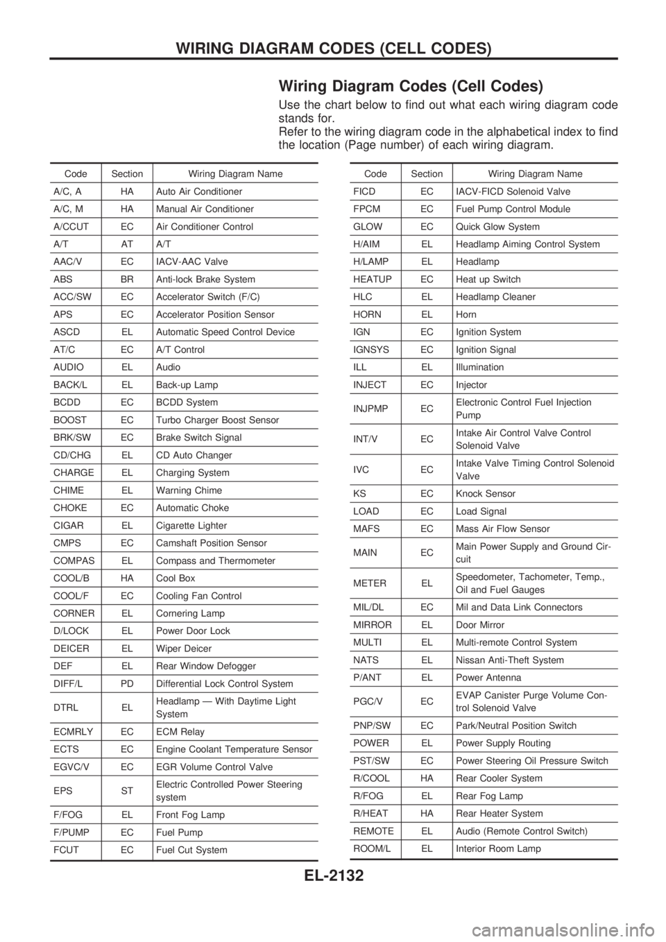
Wiring Diagram Codes (Cell Codes)
Use the chart below to find out what each wiring diagram code
stands for.
Refer to the wiring diagram code in the alphabetical index to find
the location (Page number) of each wiring diagram.
Code Section Wiring Diagram Name
A/C, A HA Auto Air Conditioner
A/C, M HA Manual Air Conditioner
A/CCUT EC Air Conditioner Control
A/T AT A/T
AAC/V EC IACV-AAC Valve
ABS BR Anti-lock Brake System
ACC/SW EC Accelerator Switch (F/C)
APS EC Accelerator Position Sensor
ASCD EL Automatic Speed Control Device
AT/C EC A/T Control
AUDIO EL Audio
BACK/L EL Back-up Lamp
BCDD EC BCDD System
BOOST EC Turbo Charger Boost Sensor
BRK/SW EC Brake Switch Signal
CD/CHG EL CD Auto Changer
CHARGE EL Charging System
CHIME EL Warning Chime
CHOKE EC Automatic Choke
CIGAR EL Cigarette Lighter
CMPS EC Camshaft Position Sensor
COMPAS EL Compass and Thermometer
COOL/B HA Cool Box
COOL/F EC Cooling Fan Control
CORNER EL Cornering Lamp
D/LOCK EL Power Door Lock
DEICER EL Wiper Deicer
DEF EL Rear Window Defogger
DIFF/L PD Differential Lock Control System
DTRL ELHeadlamp Ð With Daytime Light
System
ECMRLY EC ECM Relay
ECTS EC Engine Coolant Temperature Sensor
EGVC/V EC EGR Volume Control Valve
EPS STElectric Controlled Power Steering
system
F/FOG EL Front Fog Lamp
F/PUMP EC Fuel Pump
FCUT EC Fuel Cut SystemCode Section Wiring Diagram Name
FICD EC IACV-FICD Solenoid Valve
FPCM EC Fuel Pump Control Module
GLOW EC Quick Glow System
H/AIM EL Headlamp Aiming Control System
H/LAMP EL Headlamp
HEATUP EC Heat up Switch
HLC EL Headlamp Cleaner
HORN EL Horn
IGN EC Ignition System
IGNSYS EC Ignition Signal
ILL EL Illumination
INJECT EC Injector
INJPMP ECElectronic Control Fuel Injection
Pump
INT/V ECIntake Air Control Valve Control
Solenoid Valve
IVC ECIntake Valve Timing Control Solenoid
Valve
KS EC Knock Sensor
LOAD EC Load Signal
MAFS EC Mass Air Flow Sensor
MAIN ECMain Power Supply and Ground Cir-
cuit
METER ELSpeedometer, Tachometer, Temp.,
Oil and Fuel Gauges
MIL/DL EC Mil and Data Link Connectors
MIRROR EL Door Mirror
MULTI EL Multi-remote Control System
NATS EL Nissan Anti-Theft System
P/ANT EL Power Antenna
PGC/V ECEVAP Canister Purge Volume Con-
trol Solenoid Valve
PNP/SW EC Park/Neutral Position Switch
POWER EL Power Supply Routing
PST/SW EC Power Steering Oil Pressure Switch
R/COOL HA Rear Cooler System
R/FOG EL Rear Fog Lamp
R/HEAT HA Rear Heater System
REMOTE EL Audio (Remote Control Switch)
ROOM/L EL Interior Room Lamp
WIRING DIAGRAM CODES (CELL CODES)
EL-2132