2001 NISSAN PATROL battery
[x] Cancel search: batteryPage 49 of 273
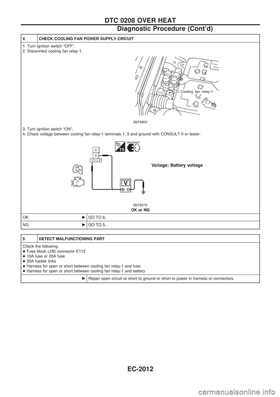
4 CHECK COOLING FAN POWER SUPPLY CIRCUIT
1. Turn ignition switch ªOFFº.
2. Disconnect cooling fan relay-1.
SEF690V
3. Turn ignition switch ªONº.
4. Check voltage between cooling fan relay-1 terminals 1, 5 and ground with CONSULT-II or tester.
SEF607X
OK or NG
OKcGO TO 6.
NGcGO TO 5.
5 DETECT MALFUNCTIONING PART
Check the following.
+Fuse block (J/B) connector E112
+10A fuse or 20A fuse
+30A fusible links
+Harness for open or short between cooling fan relay-1 and fuse
+Harness for open or short between cooling fan relay-1 and battery
cRepair open circuit or short to ground or short to power in harness or connectors.
DTC 0208 OVER HEAT
Diagnostic Procedure (Cont'd)
EC-2012
Page 51 of 273
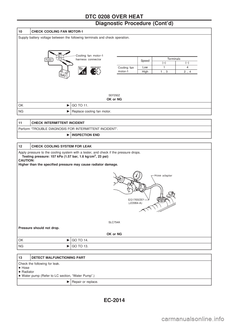
10 CHECK COOLING FAN MOTOR-1
Supply battery voltage between the following terminals and check operation.
SEF292Z
OK or NG
OKcGO TO 11.
NGcReplace cooling fan motor.
11 CHECK INTERMITTENT INCIDENT
Perform ªTROUBLE DIAGNOSIS FOR INTERMITTENT INCIDENTº.
cINSPECTION END
12 CHECK COOLING SYSTEM FOR LEAK
Apply pressure to the cooling system with a tester, and check if the pressure drops.
Testing pressure: 157 kPa (1.57 bar, 1.6 kg/cm
2, 23 psi)
CAUTION:
Higher than the specified pressure may cause radiator damage.
SLC754A
Pressure should not drop.
OK or NG
OKcGO TO 14.
NGcGO TO 13.
13 DETECT MALFUNCTIONING PART
Check the following for leak.
+Hose
+Radiator
+Water pump (Refer to LC section, ªWater Pumpº.)
cRepair or replace.
DTC 0208 OVER HEAT
Diagnostic Procedure (Cont'd)
EC-2014
Page 82 of 273

Wiring Diagram Ð POWER Ð
BATTERY POWER SUPPLY Ð IGNITION SW. IN ANY POSITION
TEL373M
POWER SUPPLY ROUTING/WAGON AND HARDTOP MODELS
EL-2005
Page 112 of 273
Bulb Replacement
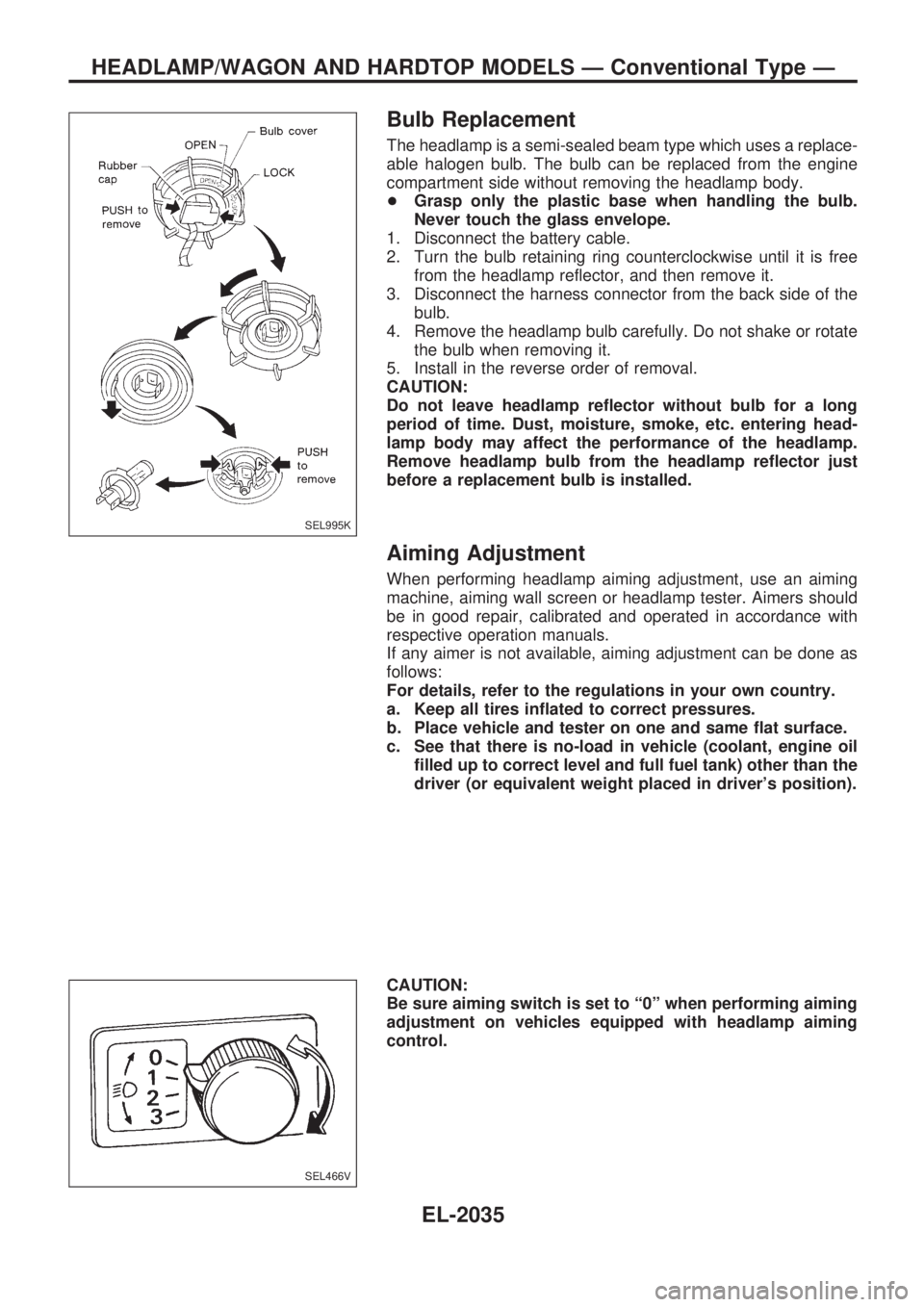
The headlamp is a semi-sealed beam type which uses a replace-
able halogen bulb. The bulb can be replaced from the engine
compartment side without removing the headlamp body.
+Grasp only the plastic base when handling the bulb.
Never touch the glass envelope.
1. Disconnect the battery cable.
2. Turn the bulb retaining ring counterclockwise until it is free
from the headlamp reflector, and then remove it.
3. Disconnect the harness connector from the back side of the
bulb.
4. Remove the headlamp bulb carefully. Do not shake or rotate
the bulb when removing it.
5. Install in the reverse order of removal.
CAUTION:
Do not leave headlamp reflector without bulb for a long
period of time. Dust, moisture, smoke, etc. entering head-
lamp body may affect the performance of the headlamp.
Remove headlamp bulb from the headlamp reflector just
before a replacement bulb is installed.
Aiming Adjustment
When performing headlamp aiming adjustment, use an aiming
machine, aiming wall screen or headlamp tester. Aimers should
be in good repair, calibrated and operated in accordance with
respective operation manuals.
If any aimer is not available, aiming adjustment can be done as
follows:
For details, refer to the regulations in your own country.
a. Keep all tires inflated to correct pressures.
b. Place vehicle and tester on one and same flat surface.
c. See that there is no-load in vehicle (coolant, engine oil
filled up to correct level and full fuel tank) other than the
driver (or equivalent weight placed in driver's position).
CAUTION:
Be sure aiming switch is set to ª0º when performing aiming
adjustment on vehicles equipped with headlamp aiming
control.
SEL995K
SEL466V
HEADLAMP/WAGON AND HARDTOP MODELS Ð Conventional Type Ð
EL-2035
Page 254 of 273
Precautions for SRS ªAIR BAGº and ªSEAT
BELT PRE-TENSIONERº Service
+Do not use electrical test equipment to check SRS circuits unless instructed to in this Service Manual.
+Before servicing the SRS, turn ignition switch ªOFFº, disconnect both battery cables and wait at least 3
minutes.
For approximately 3 minutes after the cables are removed, it is still possible for the air bag and seat belt
pre-tensioner to deploy. Therefore, do not work on any SRS connectors or wires until at least 3 minutes
have passed.
+Diagnosis sensor unit must always be installed with their arrow marks ª
Sº pointing towards the front of
the vehicle for proper operation. Also check diagnosis sensor unit for cracks, deformities or rust before
installation and replace as required.
+The spiral cable must be aligned with the neutral position since its rotations are limited. Do not attempt
to turn steering wheel or column after removal of steering gear.
+Handle air bag module carefully. Always place driver and passenger air bag modules with the pad side
facing upward and front side air bag modules (built-in type) with the stud bolt side facing down.
+Conduct self-diagnosis to check entire SRS for proper function after replacing any components.
+After air bag inflates, the front instrument panel assembly should be replaced if damaged.
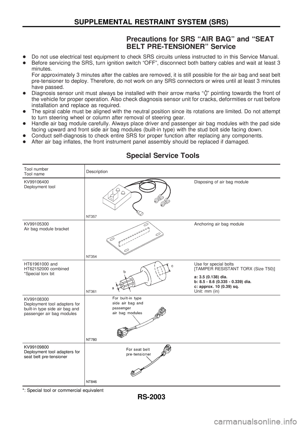
Special Service Tools
Tool number
Tool nameDescription
KV99106400
Deployment tool
NT357
Disposing of air bag module
KV99105300
Air bag module bracket
NT354
Anchoring air bag module
HT61961000 and
HT62152000 combined
*Special torx bit
NT361
Use for special bolts
[TAMPER RESISTANT TORX (Size T50)]
a: 3.5 (0.138) dia.
b: 8.5 - 8.6 (0.335 - 0.339) dia.
c: approx. 10 (0.39) sq.
Unit: mm (in)
KV99108300
Deployment tool adapters for
built-in type side air bag and
passenger air bag modules
NT780
KV99109800
Deployment tool adapters for
seat belt pre-tensioner
NT846
*: Special tool or commercial equivalent
SUPPLEMENTAL RESTRAINT SYSTEM (SRS)
RS-2003
Page 256 of 273
Removal and Installation Ð Diagnosis
Sensor Unit, Seat Belt Pre-tensioner with
Load Limiter
CAUTION:
+Before servicing SRS, turn the ignition switch off, disconnect both battery cables and wait at least
3 minutes.
+Do not use old bolts and nuts coated with bonding agent after removal; replace with new ones.
+Check diagnosis sensor unit, seat belt pre-tensioner with load limiter and satellite sensor for
proper installation.
+Check diagnosis sensor unit and satellite sensor to ensure they are free of deformities, dents,
cracks or rust. If they show any visible signs of damage, replace them with new ones.
+Check diagnosis sensor unit brackets to ensure they are free of deformities and rust.
+After replacement of diagnosis sensor unit, seat belt pre-tensioner and satellite sensor, check
SRS function and perform self-diagnosis for SRS. Refer to ªSelf-diagnosisº for details.
+Do not attempt to disassemble diagnosis sensor unit, seat belt pre-tensioner with load limiter and
satellite sensor.
+Replace diagnosis sensor unit, seat belt pre-tensioner and satellite sensor if it has been dropped
or sustained an impact.
+Do not expose seat belt pre-tensioner to temperatures exceeding 80ÉC (176ÉF).
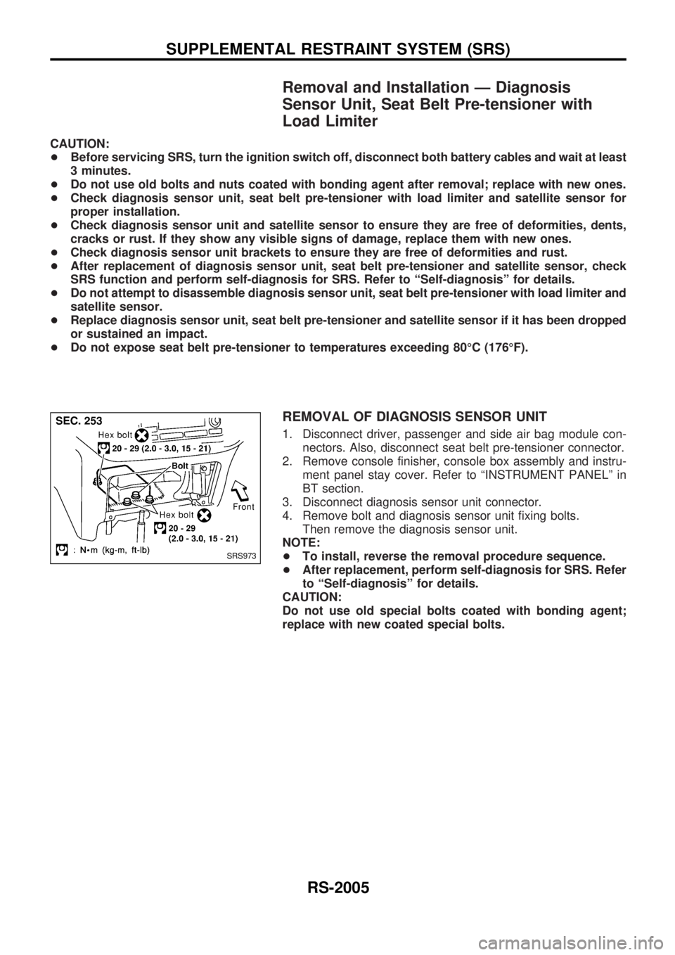
REMOVAL OF DIAGNOSIS SENSOR UNIT
1. Disconnect driver, passenger and side air bag module con-
nectors. Also, disconnect seat belt pre-tensioner connector.
2. Remove console finisher, console box assembly and instru-
ment panel stay cover. Refer to ªINSTRUMENT PANELº in
BT section.
3. Disconnect diagnosis sensor unit connector.
4. Remove bolt and diagnosis sensor unit fixing bolts.
Then remove the diagnosis sensor unit.
NOTE:
+To install, reverse the removal procedure sequence.
+After replacement, perform self-diagnosis for SRS. Refer
to ªSelf-diagnosisº for details.
CAUTION:
Do not use old special bolts coated with bonding agent;
replace with new coated special bolts.
SRS973
SUPPLEMENTAL RESTRAINT SYSTEM (SRS)
RS-2005
Page 257 of 273
Removal Ð Driver Air Bag Module and Spiral
Cable
CAUTION:
+Before servicing SRS, turn the ignition switch OFF, dis-
connect both battery cables and wait at least 3 minutes.
+Always work from the side of air bag module.
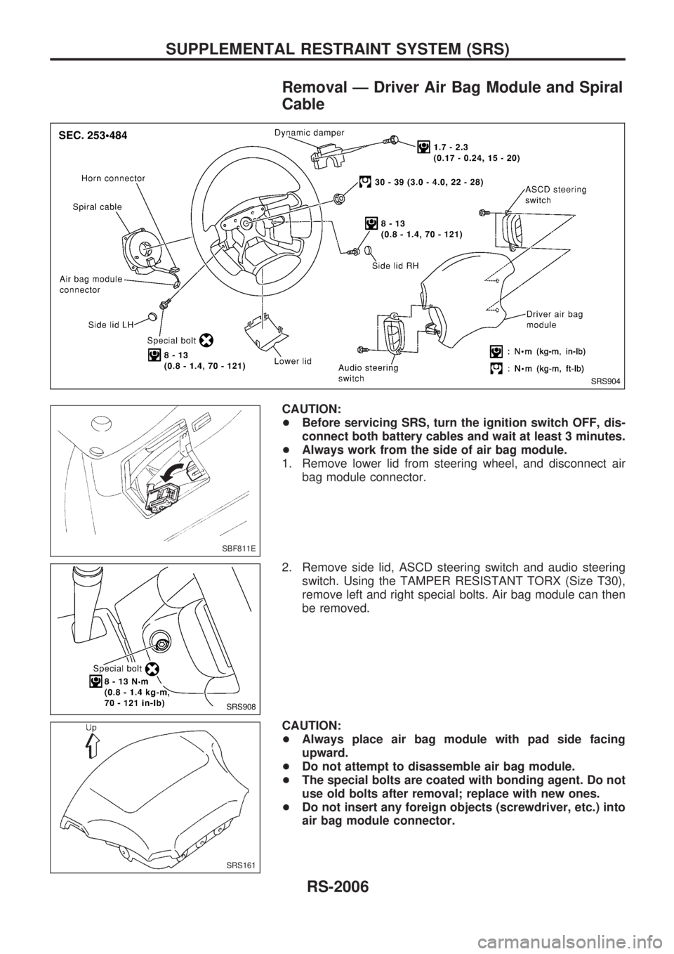
1. Remove lower lid from steering wheel, and disconnect air
bag module connector.
2. Remove side lid, ASCD steering switch and audio steering
switch. Using the TAMPER RESISTANT TORX (Size T30),
remove left and right special bolts. Air bag module can then
be removed.
CAUTION:
+Always place air bag module with pad side facing
upward.
+Do not attempt to disassemble air bag module.
+The special bolts are coated with bonding agent. Do not
use old bolts after removal; replace with new ones.
+Do not insert any foreign objects (screwdriver, etc.) into
air bag module connector.
SRS904
SBF811E
SRS908
SRS161
SUPPLEMENTAL RESTRAINT SYSTEM (SRS)
RS-2006
Page 259 of 273
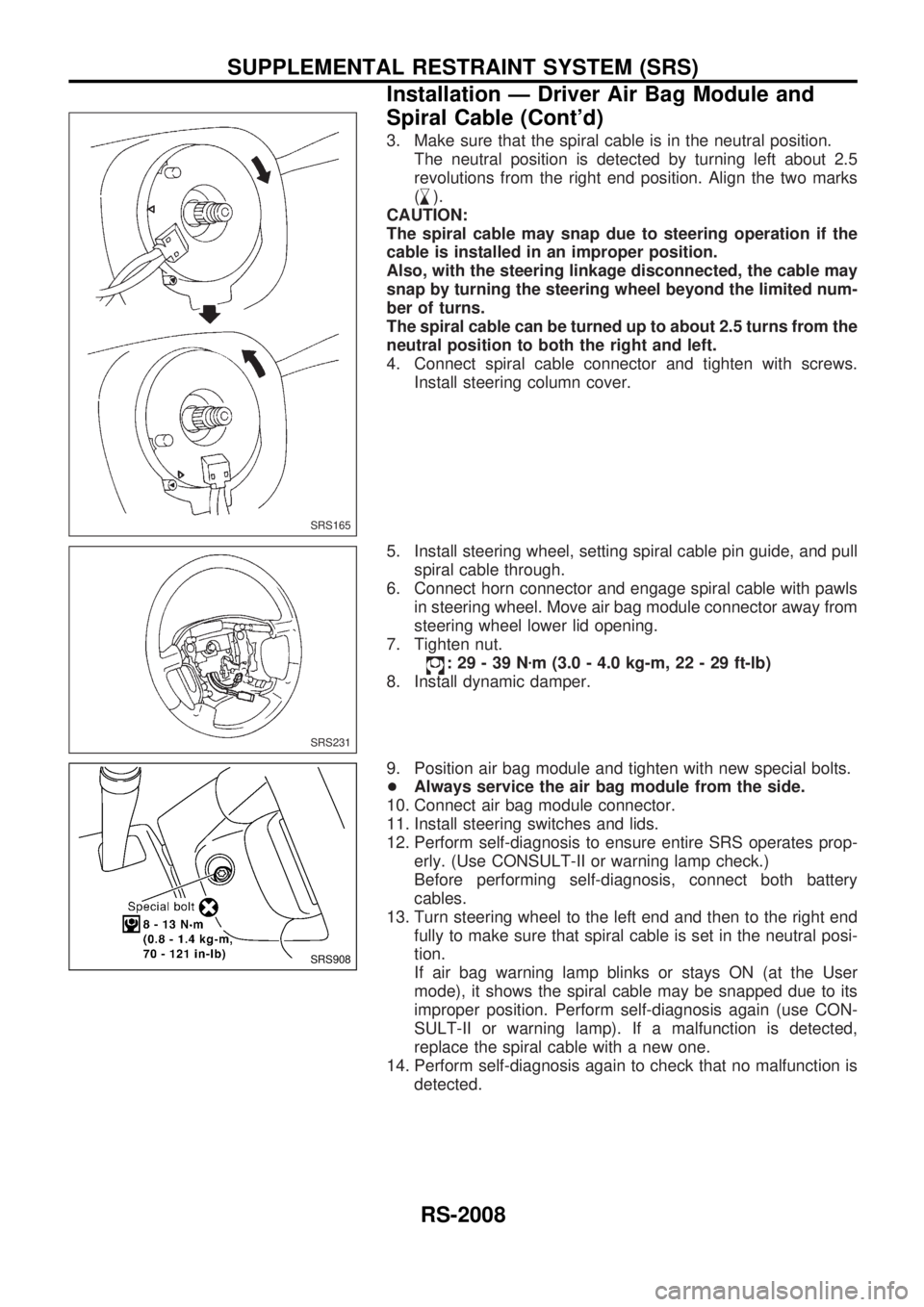
3. Make sure that the spiral cable is in the neutral position.
The neutral position is detected by turning left about 2.5
revolutions from the right end position. Align the two marks
(
,
m).
CAUTION:
The spiral cable may snap due to steering operation if the
cable is installed in an improper position.
Also, with the steering linkage disconnected, the cable may
snap by turning the steering wheel beyond the limited num-
ber of turns.
The spiral cable can be turned up to about 2.5 turns from the
neutral position to both the right and left.
4. Connect spiral cable connector and tighten with screws.
Install steering column cover.
5. Install steering wheel, setting spiral cable pin guide, and pull
spiral cable through.
6. Connect horn connector and engage spiral cable with pawls
in steering wheel. Move air bag module connector away from
steering wheel lower lid opening.
7. Tighten nut.
:29-39Nzm (3.0 - 4.0 kg-m, 22 - 29 ft-lb)
8. Install dynamic damper.
9. Position air bag module and tighten with new special bolts.
+Always service the air bag module from the side.
10. Connect air bag module connector.
11. Install steering switches and lids.
12. Perform self-diagnosis to ensure entire SRS operates prop-
erly. (Use CONSULT-II or warning lamp check.)
Before performing self-diagnosis, connect both battery
cables.
13. Turn steering wheel to the left end and then to the right end
fully to make sure that spiral cable is set in the neutral posi-
tion.
If air bag warning lamp blinks or stays ON (at the User
mode), it shows the spiral cable may be snapped due to its
improper position. Perform self-diagnosis again (use CON-
SULT-II or warning lamp). If a malfunction is detected,
replace the spiral cable with a new one.
14. Perform self-diagnosis again to check that no malfunction is
detected.
SRS165
SRS231
SRS908
SUPPLEMENTAL RESTRAINT SYSTEM (SRS)
Installation Ð Driver Air Bag Module and
Spiral Cable (Cont'd)
RS-2008