Page 260 of 273

Disposal of Air Bag Module and Seat Belt
Pre-tensioner
+Before disposing of air bag module and seat belt pre-tensioner, or vehicles equipped with such systems,
deploy the systems. If such systems have already been deployed due to an accident, dispose of them
as indicated in ªDISPOSING OF AIR BAG MODULE AND SEAT BELT PRE-TENSIONERº (RS-2013).
+When deploying the air bag module and seat belt pre-tensioner, always use the Special Service Tool;
Deployment tool KV99106400.
+When deploying the air bag module and seat belt pre-tensioner, stand at least 5 m (16 ft) away from the
deployment component.
+When deploying air bag module and seat belt pre-tensioner, a fairly loud noise is made, followed by
smoke being released. The smoke is not poisonous, however, be careful not to inhale smoke since it
irritates the throat and can cause choking.
+Always activate one air bag module at a time.
+Due to heat, leave air bag module unattended for more than 30 minutes after deployment. Also leave
seat belt pre-tensioner unattended for move than 10 minutes after deployment.
+Be sure to wear gloves when handling a deployed air bag module and seat belt pre-tensioner.
+Never apply water to the deployed air bag module and seat belt pre-tensioner.
+Wash your hands clean after finishing work.
+Place the vehicle outdoors with an open space of at least 6 m (20 ft) on all sides when deploying air
bag module and seat belt pre-tensioner while mounted in vehicle.
+Use a voltmeter to make sure the vehicle battery is fully charged.
+Do not dispose of the air bag module and seat belt pre-tensioner un-deployed.
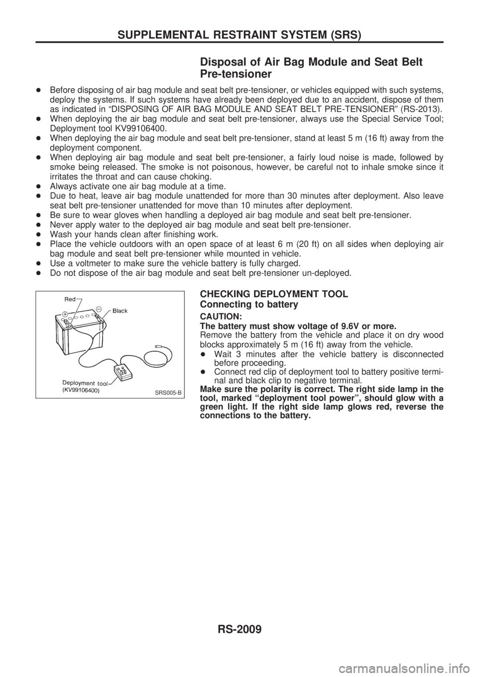
CHECKING DEPLOYMENT TOOL
Connecting to battery
CAUTION:
The battery must show voltage of 9.6V or more.
Remove the battery from the vehicle and place it on dry wood
blocks approximately 5 m (16 ft) away from the vehicle.
+Wait 3 minutes after the vehicle battery is disconnected
before proceeding.
+Connect red clip of deployment tool to battery positive termi-
nal and black clip to negative terminal.
Make sure the polarity is correct. The right side lamp in the
tool, marked ªdeployment tool powerº, should glow with a
green light. If the right side lamp glows red, reverse the
connections to the battery.
SRS005-B
SUPPLEMENTAL RESTRAINT SYSTEM (SRS)
RS-2009
Page 261 of 273

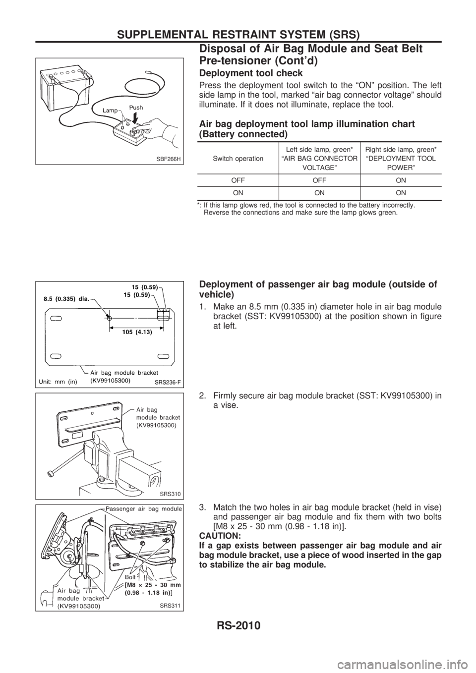
Deployment tool check
Press the deployment tool switch to the ªONº position. The left
side lamp in the tool, marked ªair bag connector voltageº should
illuminate. If it does not illuminate, replace the tool.
Air bag deployment tool lamp illumination chart
(Battery connected)
Switch operationLeft side lamp, green*
ªAIR BAG CONNECTOR
VOLTAGEºRight side lamp, green*
ªDEPLOYMENT TOOL
POWERº
OFF OFF ON
ON ON ON
*: If this lamp glows red, the tool is connected to the battery incorrectly.
Reverse the connections and make sure the lamp glows green.
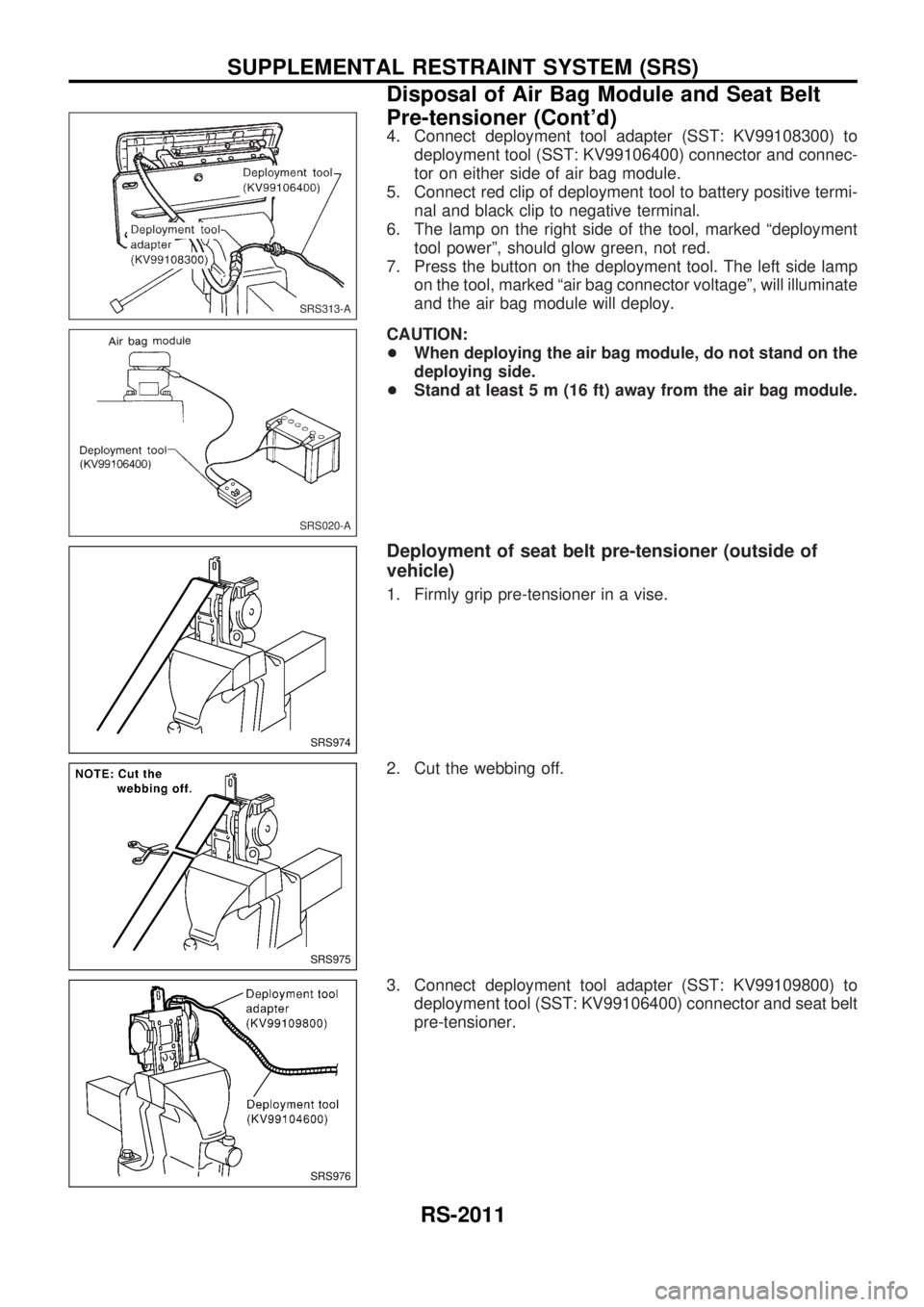
Deployment of passenger air bag module (outside of
vehicle)
1. Make an 8.5 mm (0.335 in) diameter hole in air bag module
bracket (SST: KV99105300) at the position shown in figure
at left.
2. Firmly secure air bag module bracket (SST: KV99105300) in
a vise.
3. Match the two holes in air bag module bracket (held in vise)
and passenger air bag module and fix them with two bolts
[M8 x 25 - 30 mm (0.98 - 1.18 in)].
CAUTION:
If a gap exists between passenger air bag module and air
bag module bracket, use a piece of wood inserted in the gap
to stabilize the air bag module.
SBF266H
SRS236-F
SRS310
SRS311
SUPPLEMENTAL RESTRAINT SYSTEM (SRS)
Disposal of Air Bag Module and Seat Belt
Pre-tensioner (Cont'd)
RS-2010
Page 262 of 273

4. Connect deployment tool adapter (SST: KV99108300) to
deployment tool (SST: KV99106400) connector and connec-
tor on either side of air bag module.
5. Connect red clip of deployment tool to battery positive termi-
nal and black clip to negative terminal.
6. The lamp on the right side of the tool, marked ªdeployment
tool powerº, should glow green, not red.
7. Press the button on the deployment tool. The left side lamp
on the tool, marked ªair bag connector voltageº, will illuminate
and the air bag module will deploy.
CAUTION:
+When deploying the air bag module, do not stand on the
deploying side.
+Stand at least 5 m (16 ft) away from the air bag module.
Deployment of seat belt pre-tensioner (outside of
vehicle)
1. Firmly grip pre-tensioner in a vise.
2. Cut the webbing off.
3. Connect deployment tool adapter (SST: KV99109800) to
deployment tool (SST: KV99106400) connector and seat belt
pre-tensioner.
SRS313-A
SRS020-A
SRS974
SRS975
SRS976
SUPPLEMENTAL RESTRAINT SYSTEM (SRS)
Disposal of Air Bag Module and Seat Belt
Pre-tensioner (Cont'd)
RS-2011
Page 263 of 273

4. Connect red clip of deployment tool to battery positive termi-
nal and black clip to negative terminal.
5. The lamp on the right side of the tool, marked ªdeployment
tool powerº, should glow green, not red.
6. Press the button on the deployment tool. The left side lamp
on the tool, marked ªseat belt pre-tensioner connector
voltageº, will illuminate and the seat belt pre-tensioner will
deploy.
CAUTION:
When deploying the seat belt pre-tensioner, stand at least 5
m (16 ft) away from the seat belt pre-tensioner.
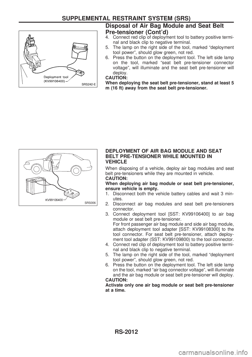
DEPLOYMENT OF AIR BAG MODULE AND SEAT
BELT PRE-TENSIONER WHILE MOUNTED IN
VEHICLE
When disposing of a vehicle, deploy air bag modules and seat
belt pre-tensioners while they are mounted in vehicle.
CAUTION:
When deploying air bag module or seat belt pre-tensioner,
ensure vehicle is empty.
1. Disconnect both the vehicle battery cables and wait 3 min-
utes.
2. Disconnect air bag modules and seat belt pre-tensioners
connector.
3. Connect deployment tool [SST: KV99106400] to air bag
module or seat belt pre-tensioner.
For front passenger air bag module and side air bag module,
attach deployment tool adapter [SST: KV99108300] to the
tool connector. For seat belt pre-tensioner, attach deploy-
ment tool adapter (SST: KV99109800) to the tool connector.
4. Connect red clip of deployment tool to battery positive termi-
nal and black clip to negative terminal.
5. The lamp on the right side of the tool, marked ªdeployment
tool powerº, should glow green, not red.
6. Press the button on the deployment tool. The left side lamp
on the tool, marked ªair bag connector voltageº, will illuminate
and the air bag module or seat belt pre-tensioner will deploy.
CAUTION:
Activate only one air bag module or seat belt pre-tensioner
at a time.
SRS242-E
SRS006
SUPPLEMENTAL RESTRAINT SYSTEM (SRS)
Disposal of Air Bag Module and Seat Belt
Pre-tensioner (Cont'd)
RS-2012
Page 268 of 273
![NISSAN PATROL 2001 Electronic Repair Manual HOW TO ERASE SELF-DIAGNOSIS RESULTS
With CONSULT-II
+ªSELF-DIAG [CURRENT]º
A current Self-diagnosis result is displayed on the CON-
SULT-II screen in real time. After the malfunction is repaired
com NISSAN PATROL 2001 Electronic Repair Manual HOW TO ERASE SELF-DIAGNOSIS RESULTS
With CONSULT-II
+ªSELF-DIAG [CURRENT]º
A current Self-diagnosis result is displayed on the CON-
SULT-II screen in real time. After the malfunction is repaired
com](/manual-img/5/57366/w960_57366-267.png)
HOW TO ERASE SELF-DIAGNOSIS RESULTS
With CONSULT-II
+ªSELF-DIAG [CURRENT]º
A current Self-diagnosis result is displayed on the CON-
SULT-II screen in real time. After the malfunction is repaired
completely, no malfunction is detected on ªSELF-DIAG
[CURRENT]º.
+ªSELF-DIAG [PAST]º
Return to the ªSELF-DIAG [CURRENT]º CONSULT-II screen
by pushing ªBACKº key of CONSULT-II and select ªSELF-
DIAG [CURRENT]º in ªSELECT DIAG MODEº. Touch
ªERASEº in ªSELF-DIAG [CURRENT]º mode.
NOTE:
If the memory of the malfunction in ªSELF-DIAG [PAST]º is
not erased, the User mode shows the system malfunction by
the operation of the warning lamp even if the malfunction is
repaired completely.
+ªTROUBLE DIAG RECORDº
The memory of ªTROUBLE DIAG RECORDº cannot be
erased.
Without CONSULT-II
After a malfunction is repaired, return Diagnosis mode to User
mode by switching the ignition ªOFFº for at least 1 second, then
back ªONº. At that time, the self-diagnostic result is cleared.
How to Perform Trouble Diagnoses for Quick
and Accurate Repair
A good understanding of the malfunction conditions can make troubleshooting faster and more accurate.
In general, each customer feels differently about a malfunction. It is important to fully understand the symp-
toms or conditions for a customer complaint.
INFORMATION FROM CUSTOMER
WHAT ........ Vehicle model
WHEN ....... Date, Frequencies
WHERE ..... Road conditions
HOW .......... Operating conditions, Symptoms
PRELIMINARY CHECK
Check that the following parts are in good order.
+Battery [Refer to EL section (ªBATTERYº) of Service Manual.]
+Fuse [Refer to EL section (ªFuseº, ªPOWER SUPPLY ROUTINGº) of Service Manual.]
+System component-to-harness connections
SRS701
TROUBLE DIAGNOSES Ð Supplemental Restraint System (SRS)
Trouble Diagnoses Introduction (Cont'd)
RS-2017