2001 NISSAN PATROL check engine
[x] Cancel search: check enginePage 27 of 273
Body Front End
+When removing or installing hood, place a cloth or other padding on front fender panel and cowl top.
This prevents vehicle body from being scratched.
+Bumper fascia is made of plastic. Do not use excessive force and be sure to keep oil away from it.
+Hood adjustment: Adjust at hinge portion.
+Hood lock adjustment: After adjusting, check hood lock control operation. Apply a coat of grease to hood
locks engaging mechanism.
+Hood opener: Do not attempt to bend cable forcibly. Doing so increases effort required to unlock hood.
REMOVAL Ð Front bumper assembly
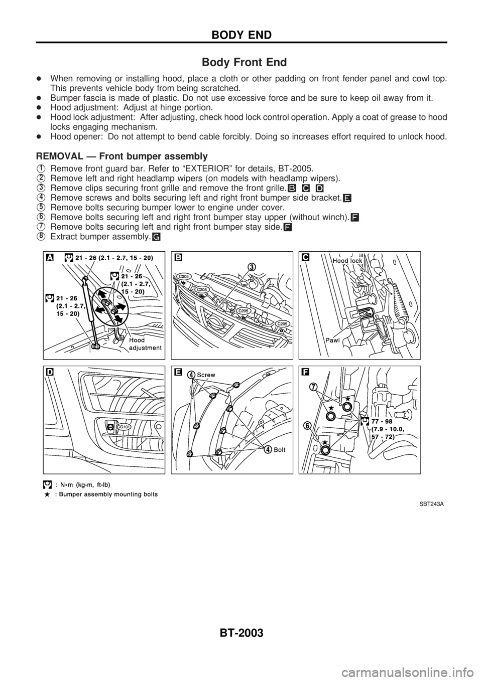
V1Remove front guard bar. Refer to ªEXTERIORº for details, BT-2005.
V2Remove left and right headlamp wipers (on models with headlamp wipers).
V3Remove clips securing front grille and remove the front grille.
V4Remove screws and bolts securing left and right front bumper side bracket.
V5Remove bolts securing bumper lower to engine under cover.
V6Remove bolts securing left and right front bumper stay upper (without winch).
V7Remove bolts securing left and right front bumper stay side.
V8Extract bumper assembly.
SBT243A
BODY END
BT-2003
Page 48 of 273
Diagnostic Procedure
1 INSPECTION START
Do you have CONSULT-II?
Yes or No
YescGO TO 2.
NocGO TO 3.
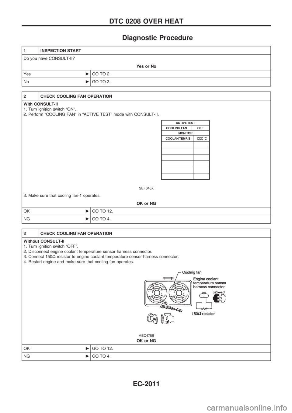
2 CHECK COOLING FAN OPERATION
With CONSULT-II
1. Turn ignition switch ªONº.
2. Perform ªCOOLING FANº in ªACTIVE TESTº mode with CONSULT-II.
SEF646X
3. Make sure that cooling fan-1 operates.
OK or NG
OKcGO TO 12.
NGcGO TO 4.
3 CHECK COOLING FAN OPERATION
Without CONSULT-II
1. Turn ignition switch ªOFFº.
2. Disconnect engine coolant temperature sensor harness connector.
3. Connect 150Wresistor to engine coolant temperature sensor harness connector.
4. Restart engine and make sure that cooling fan operates.
MEC475B
OK or NG
OKcGO TO 12.
NGcGO TO 4.
DTC 0208 OVER HEAT
EC-2011
Page 53 of 273
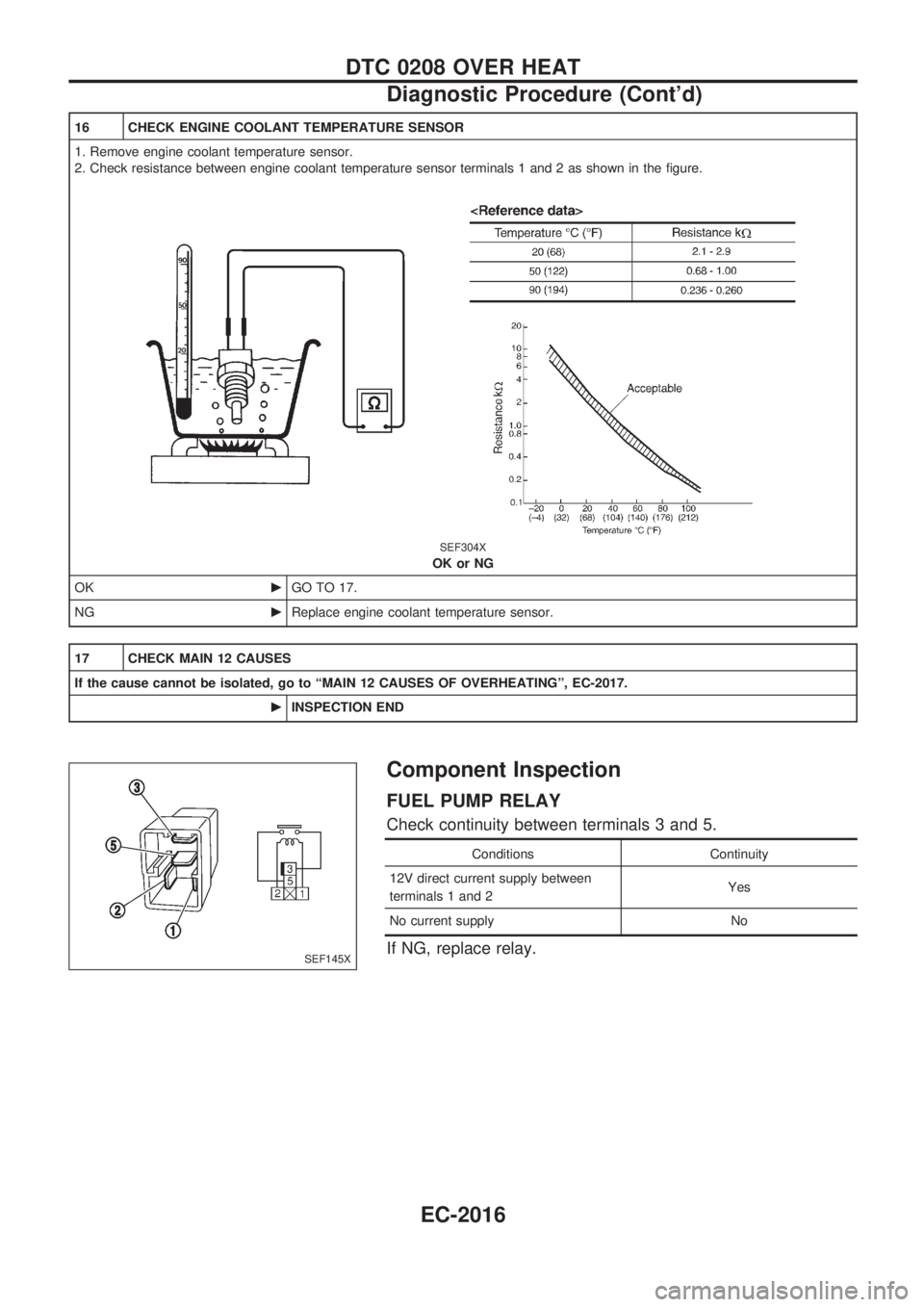
16 CHECK ENGINE COOLANT TEMPERATURE SENSOR
1. Remove engine coolant temperature sensor.
2. Check resistance between engine coolant temperature sensor terminals 1 and 2 as shown in the figure.
SEF304X
OK or NG
OKcGO TO 17.
NGcReplace engine coolant temperature sensor.
17 CHECK MAIN 12 CAUSES
If the cause cannot be isolated, go to ªMAIN 12 CAUSES OF OVERHEATINGº, EC-2017.
cINSPECTION END
Component Inspection
FUEL PUMP RELAY
Check continuity between terminals 3 and 5.
Conditions Continuity
12V direct current supply between
terminals 1 and 2Yes
No current supply No
If NG, replace relay.SEF145X
DTC 0208 OVER HEAT
Diagnostic Procedure (Cont'd)
EC-2016
Page 54 of 273
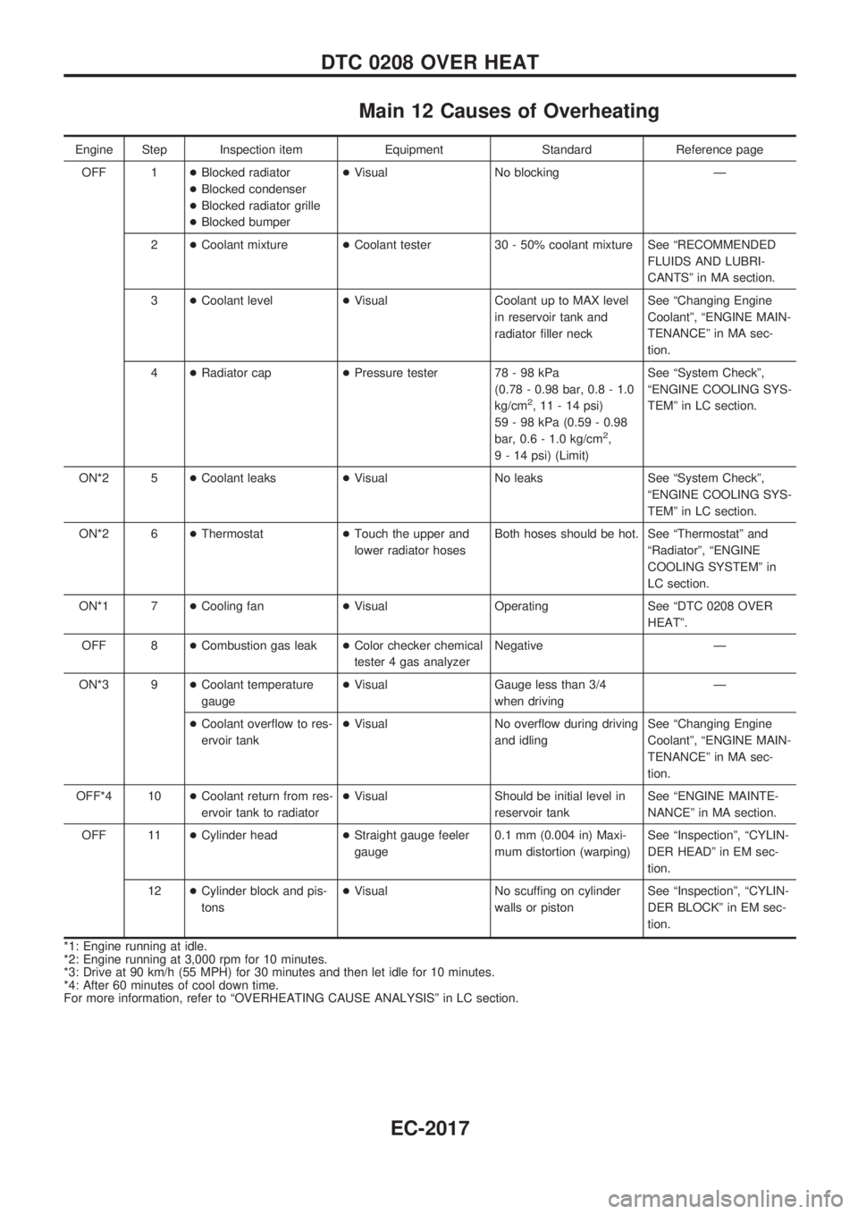
Main 12 Causes of Overheating
Engine Step Inspection item Equipment Standard Reference page
OFF 1+Blocked radiator
+Blocked condenser
+Blocked radiator grille
+Blocked bumper+Visual No blocking Ð
2+Coolant mixture+Coolant tester 30 - 50% coolant mixture See ªRECOMMENDED
FLUIDS AND LUBRI-
CANTSº in MA section.
3+Coolant level+Visual Coolant up to MAX level
in reservoir tank and
radiator filler neckSee ªChanging Engine
Coolantº, ªENGINE MAIN-
TENANCEº in MA sec-
tion.
4+Radiator cap+Pressure tester 78 - 98 kPa
(0.78 - 0.98 bar, 0.8 - 1.0
kg/cm
2, 11 - 14 psi)
59 - 98 kPa (0.59 - 0.98
bar, 0.6 - 1.0 kg/cm
2,
9 - 14 psi) (Limit)See ªSystem Checkº,
ªENGINE COOLING SYS-
TEMº in LC section.
ON*2 5+Coolant leaks+Visual No leaks See ªSystem Checkº,
ªENGINE COOLING SYS-
TEMº in LC section.
ON*2 6+Thermostat+Touch the upper and
lower radiator hosesBoth hoses should be hot. See ªThermostatº and
ªRadiatorº, ªENGINE
COOLING SYSTEMº in
LC section.
ON*1 7+Cooling fan+Visual Operating See ªDTC 0208 OVER
HEATº.
OFF 8+Combustion gas leak+Color checker chemical
tester 4 gas analyzerNegative Ð
ON*3 9+Coolant temperature
gauge+Visual Gauge less than 3/4
when drivingÐ
+Coolant overflow to res-
ervoir tank+Visual No overflow during driving
and idlingSee ªChanging Engine
Coolantº, ªENGINE MAIN-
TENANCEº in MA sec-
tion.
OFF*4 10+Coolant return from res-
ervoir tank to radiator+Visual Should be initial level in
reservoir tankSee ªENGINE MAINTE-
NANCEº in MA section.
OFF 11+Cylinder head+Straight gauge feeler
gauge0.1 mm (0.004 in) Maxi-
mum distortion (warping)See ªInspectionº, ªCYLIN-
DER HEADº in EM sec-
tion.
12+Cylinder block and pis-
tons+Visual No scuffing on cylinder
walls or pistonSee ªInspectionº, ªCYLIN-
DER BLOCKº in EM sec-
tion.
*1: Engine running at idle.
*2: Engine running at 3,000 rpm for 10 minutes.
*3: Drive at 90 km/h (55 MPH) for 30 minutes and then let idle for 10 minutes.
*4: After 60 minutes of cool down time.
For more information, refer to ªOVERHEATING CAUSE ANALYSISº in LC section.
DTC 0208 OVER HEAT
EC-2017
Page 78 of 273
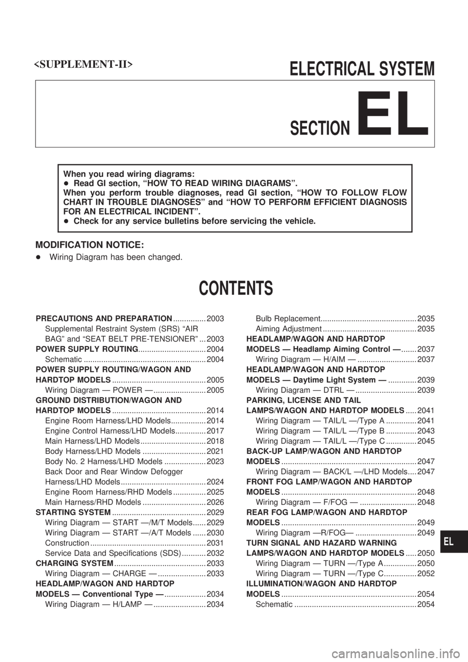
ELECTRICAL SYSTEM
SECTION
EL
When you read wiring diagrams:
+Read GI section, ªHOW TO READ WIRING DIAGRAMSº.
When you perform trouble diagnoses, read GI section, ªHOW TO FOLLOW FLOW
CHART IN TROUBLE DIAGNOSESº and ªHOW TO PERFORM EFFICIENT DIAGNOSIS
FOR AN ELECTRICAL INCIDENTº.
+Check for any service bulletins before servicing the vehicle.
MODIFICATION NOTICE:
+Wiring Diagram has been changed.
CONTENTS
PRECAUTIONS AND PREPARATION............... 2003
Supplemental Restraint System (SRS) ªAIR
BAGº and ªSEAT BELT PRE-TENSIONERº ... 2003
POWER SUPPLY ROUTING............................... 2004
Schematic ........................................................ 2004
POWER SUPPLY ROUTING/WAGON AND
HARDTOP MODELS........................................... 2005
Wiring Diagram Ð POWER Ð ........................ 2005
GROUND DISTRIBUTION/WAGON AND
HARDTOP MODELS........................................... 2014
Engine Room Harness/LHD Models................ 2014
Engine Control Harness/LHD Models.............. 2017
Main Harness/LHD Models .............................. 2018
Body Harness/LHD Models ............................. 2021
Body No. 2 Harness/LHD Models ................... 2023
Back Door and Rear Window Defogger
Harness/LHD Models ....................................... 2024
Engine Room Harness/RHD Models ............... 2025
Main Harness/RHD Models ............................. 2026
STARTING SYSTEM........................................... 2029
Wiring Diagram Ð START Ð/M/T Models...... 2029
Wiring Diagram Ð START Ð/A/T Models ...... 2030
Construction ..................................................... 2031
Service Data and Specifications (SDS) ........... 2032
CHARGING SYSTEM.......................................... 2033
Wiring Diagram Ð CHARGE Ð ...................... 2033
HEADLAMP/WAGON AND HARDTOP
MODELS Ð Conventional Type Ð................... 2034
Wiring Diagram Ð H/LAMP Ð ........................ 2034Bulb Replacement............................................ 2035
Aiming Adjustment ........................................... 2035
HEADLAMP/WAGON AND HARDTOP
MODELS Ð Headlamp Aiming Control Ð....... 2037
Wiring Diagram Ð H/AIM Ð ........................... 2037
HEADLAMP/WAGON AND HARDTOP
MODELS Ð Daytime Light System Ð............. 2039
Wiring Diagram Ð DTRL Ð ............................ 2039
PARKING, LICENSE AND TAIL
LAMPS/WAGON AND HARDTOP MODELS..... 2041
Wiring Diagram Ð TAIL/L Ð/Type A .............. 2041
Wiring Diagram Ð TAIL/L Ð/Type B .............. 2043
Wiring Diagram Ð TAIL/L Ð/Type C .............. 2045
BACK-UP LAMP/WAGON AND HARDTOP
MODELS.............................................................. 2047
Wiring Diagram Ð BACK/L Ð/LHD Models.... 2047
FRONT FOG LAMP/WAGON AND HARDTOP
MODELS.............................................................. 2048
Wiring Diagram Ð F/FOG Ð .......................... 2048
REAR FOG LAMP/WAGON AND HARDTOP
MODELS.............................................................. 2049
Wiring Diagram ÐR/FOGÐ ............................ 2049
TURN SIGNAL AND HAZARD WARNING
LAMPS/WAGON AND HARDTOP MODELS..... 2050
Wiring Diagram Ð TURN Ð/Type A ............... 2050
Wiring Diagram Ð TURN Ð/Type C............... 2052
ILLUMINATION/WAGON AND HARDTOP
MODELS.............................................................. 2054
Schematic ........................................................ 2054
EL