2001 NISSAN PATROL steering wheel
[x] Cancel search: steering wheelPage 26 of 273
Service Notice
+When removing or installing various parts, place a cloth or padding onto the vehicle body to prevent
scratches.
+Handle trim, molding, instruments, grille, etc. carefully during removing or installing. Be careful not to soil
or damage them.
+Apply sealing compound where necessary when installing parts.
+When applying sealing compound, be careful that the sealing compound does not protrude from parts.
+When replacing any metal parts (for example body outer panel, members, etc.), be sure to take rust
prevention measures.
Supplemental Restraint System (SRS) ªAIR
BAGº and ªSEAT BELT PRE-TENSIONERº
The Supplemental Restraint System such as ªAIR BAGº and ªSEAT BELT PRE-TENSIONERº used along
with a seat belt, helps to reduce the risk or severity of injury to the driver and front passenger for certain
types of collision. The SRS system composition which is available to NISSAN MODEL Y61 is as follows (The
composition varies according to the destination and optional equipment.):
+For a frontal collision
The Supplemental Restraint System consists of driver air bag module (located in the center of the
steering wheel), front passenger air bag module (located on the instrument panel on passenger side),
seat belt pre-tensioners, a diagnosis sensor unit, warning lamp, wiring harness and spiral cable.
+For a side collision
The Supplemental Restraint System consists of front side air bag module (located in the outer side of
front seat), satellite sensor, diagnosis sensor unit (one of components of air bags for a frontal collision),
wiring harness, warning lamp (one of components of air bags for a frontal collision).
Information necessary to service the system safely is included in theRS sectionof this Service Manual.
WARNING:
+To avoid rendering the SRS inoperative, which could increase the risk of personal injury or death
in the event of a collision which would result in air bag inflation, all maintenance should be per-
formed by an authorized NISSAN dealer.
+Improper maintenance, including incorrect removal and installation of the SRS, can lead to per-
sonal injury caused by unintentional activation of the system. For removal of Spiral Cable and
Air Bag Module, see the RS section.
+Do not use electrical test equipment on any circuit related to the SRS unless instructed to in this
Service Manual. SRS wiring harnesses can be identified with yellow harness connector.
PRECAUTIONS
BT-2002
Page 80 of 273
Supplemental Restraint System (SRS) ªAIR
BAGº and ªSEAT BELT PRE-TENSIONERº
The Supplemental Restraint System such as ªAIR BAGº and ªSEAT BELT PRE-TENSIONERº used along
with a seat belt, helps to reduce the risk or severity of injury to the driver and front passenger for certain
types of collision. The SRS system composition which is available to NISSAN MODEL Y61 is as follows (The
composition varies according to the destination and optional equipment.):
+For a frontal collision
The Supplemental Restraint System consists of driver air bag module (located in the center of the
steering wheel), front passenger air bag module (located on the instrument panel on passenger side),
seat belt pre-tensioners, a diagnosis sensor unit, warning lamp, wiring harness and spiral cable.
+For a side collision
The Supplemental Restraint System consists of front side air bag module (located in the outer side of
front seat), satellite sensor, diagnosis sensor unit (one of components of air bags for a frontal collision),
wiring harness, warning lamp (one of components of air bags for a frontal collision).
Information necessary to service the system safely is included in theRS sectionof this Service Manual.
WARNING:
+To avoid rendering the SRS inoperative, which could increase the risk of personal injury or death
in the event of a collision which would result in air bag inflation, all maintenance should be per-
formed by an authorized NISSAN dealer.
+Improper maintenance, including incorrect removal and installation of the SRS, can lead to per-
sonal injury caused by intentional activation of the system. For removal of Spiral Cable and Air
Bag Module, see the RS section.
+Do not use electrical test equipment on any circuit related to the SRS unless instructed to in this
Service Manual. SRS wiring harnesses can be identified by yellow harness connector.
PRECAUTIONS AND PREPARATION
EL-2003
Page 217 of 273
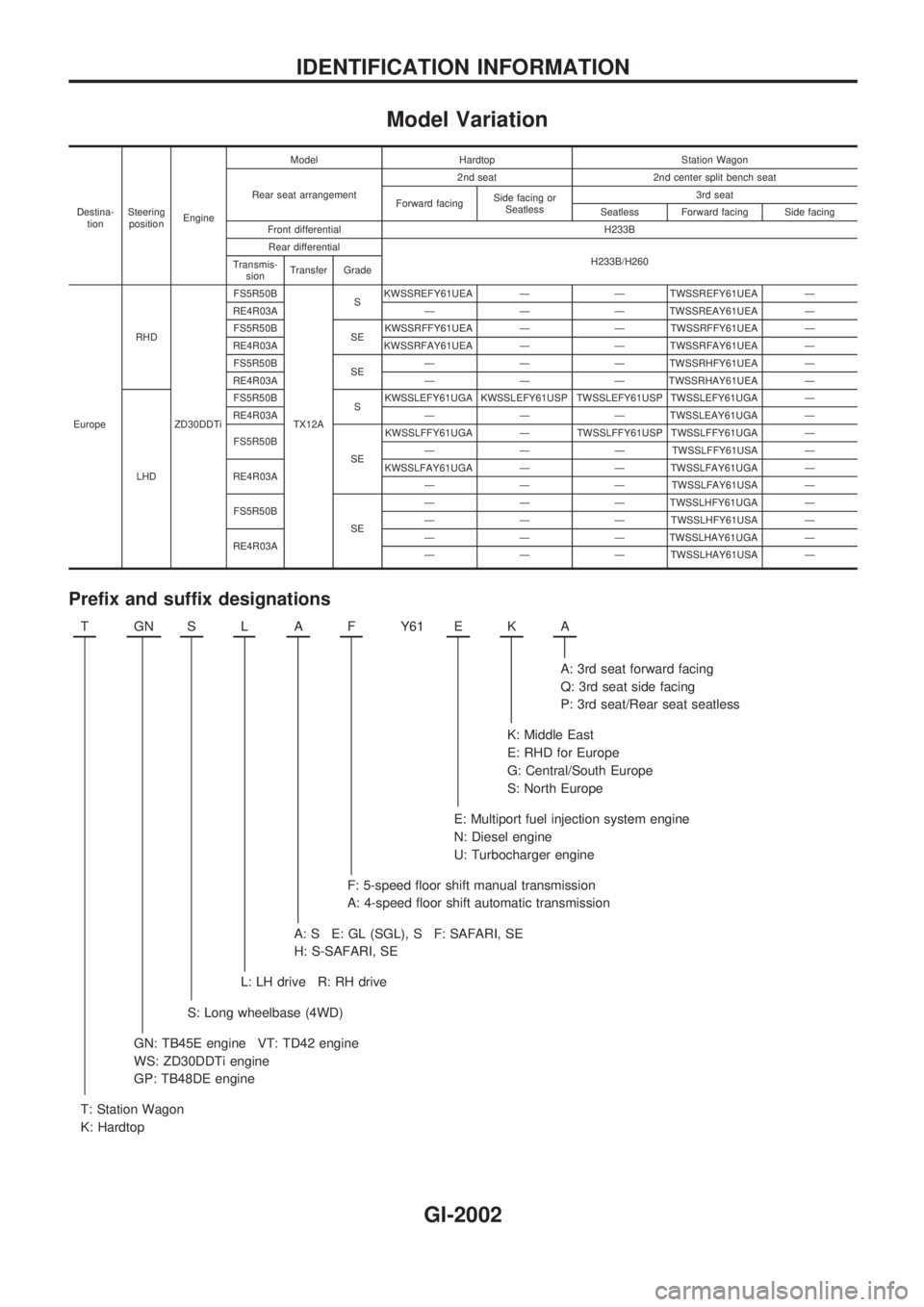
Model Variation
Destina-
tionSteering
positionEngineModel Hardtop Station Wagon
Rear seat arrangement2nd seat 2nd center split bench seat
Forward facingSide facing or
Seatless3rd seat
Seatless Forward facing Side facing
Front differential H233B
Rear differential
H233B/H260
Transmis-
sionTransfer Grade
EuropeRHD
ZD30DDTiFS5R50B
TX12ASKWSSREFY61UEA Ð Ð TWSSREFY61UEA Ð
RE4R03A Ð Ð Ð TWSSREAY61UEA Ð
FS5R50B
SEKWSSRFFY61UEA Ð Ð TWSSRFFY61UEA Ð
RE4R03A KWSSRFAY61UEA Ð Ð TWSSRFAY61UEA Ð
FS5R50B
SEÐ Ð Ð TWSSRHFY61UEA Ð
RE4R03A Ð Ð Ð TWSSRHAY61UEA Ð
LHDFS5R50B
SKWSSLEFY61UGA KWSSLEFY61USP TWSSLEFY61USP TWSSLEFY61UGA Ð
RE4R03A Ð Ð Ð TWSSLEAY61UGA Ð
FS5R50B
SEKWSSLFFY61UGA Ð TWSSLFFY61USP TWSSLFFY61UGA Ð
Ð Ð Ð TWSSLFFY61USA Ð
RE4R03AKWSSLFAY61UGA Ð Ð TWSSLFAY61UGA Ð
Ð Ð Ð TWSSLFAY61USA Ð
FS5R50B
SEÐ Ð Ð TWSSLHFY61UGA Ð
Ð Ð Ð TWSSLHFY61USA Ð
RE4R03AÐ Ð Ð TWSSLHAY61UGA Ð
Ð Ð Ð TWSSLHAY61USA Ð
Prefix and suffix designations
TGNSLAFY61 EKA
A: 3rd seat forward facing
Q: 3rd seat side facing
P: 3rd seat/Rear seat seatless
K: Middle East
E: RHD for Europe
G: Central/South Europe
S: North Europe
E: Multiport fuel injection system engine
N: Diesel engine
U: Turbocharger engine
F: 5-speed floor shift manual transmission
A: 4-speed floor shift automatic transmission
A: S E: GL (SGL), S F: SAFARI, SE
H: S-SAFARI, SE
L: LH drive R: RH drive
S: Long wheelbase (4WD)
GN: TB45E engine VT: TD42 engine
WS: ZD30DDTi engine
GP: TB48DE engine
T: Station Wagon
K: Hardtop
IDENTIFICATION INFORMATION
GI-2002
Page 221 of 273
Supplemental Restraint System (SRS) ªAIR
BAGº and ªSEAT BELT PRE-TENSIONERº
The Supplemental Restraint System such as ªAIR BAGº and ªSEAT BELT PRE-TENSIONERº used along
with a seat belt, helps to reduce the risk or severity of injury to the driver and front passenger for certain
types of collision. The SRS system composition which is available to NISSAN MODEL Y61 is as follows (The
composition varies according to the destination and optional equipment.):
+For a frontal collision
The Supplemental Restraint System consists of driver air bag module (located in the center of the
steering wheel), front passenger air bag module (located on the instrument panel on passenger side),
seat belt pre-tensioners, a diagnosis sensor unit, warning lamp, wiring harness and spiral cable.
+For a side collision
The Supplemental Restraint System consists of front side air bag module (located in the outer side of
front seat), satellite sensor, diagnosis sensor unit (one of components of air bags for a frontal collision),
wiring harness, warning lamp (one of components of air bags for a frontal collision).
Information necessary to service the system safely is included in theRS sectionof this Service Manual.
WARNING:
+To avoid rendering the SRS inoperative, which could increase the risk of personal injury or death
in the event of a collision which would result in air bag inflation, all maintenance should be per-
formed by an authorized NISSAN dealer.
+Improper maintenance, including incorrect removal and installation of the SRS, can lead to per-
sonal injury caused by unintentional activation of the system. For removal of Spiral Cable and
Air Bag Module, see the RS section.
+Do not use electrical test equipment on any circuit related to the SRS unless instructed to in this
Service Manual. Spiral cable and wiring harnesses covered with yellow insulation tape either just
before the harness connectors or for the complete harness are related to the SRS.
PRECAUTIONS AND PREPARATION
HA-2002
Page 253 of 273
Supplemental Restraint System (SRS) ªAIR
BAGº and ªSEAT BELT PRE-TENSIONERº
The Supplemental Restraint System such as ªAIR BAGº and ªSEAT BELT PRE-TENSIONERº used along
with a seat belt, helps to reduce the risk or severity of injury to the driver and front passenger for certain
types of collision. The SRS composition which is available to NISSAN MODEL Y61 is as follows (The com-
position varies according to the destination and optional equipment.):
+For a frontal collision
The Supplemental Restraint System consists of driver air bag module (located in the center of the
steering wheel), front passenger air bag module (located on the instrument panel on passenger side),
seat belt pre-tensioners, a diagnosis sensor unit, warning lamp, wiring harness and spiral cable.
+For a side collision
The Supplemental Restraint System consists of front side air bag module (located in the outer side of
front seat), satellite sensor, diagnosis sensor unit (one of components of air bags for a frontal collision),
wiring harness, warning lamp (one of components of air bags for a frontal collision).
WARNING:
+To avoid rendering the SRS inoperative, which could increase the risk of personal injury or death
in the event of a collision which would result in air bag inflation, all maintenance should be per-
formed by an authorized NISSAN dealer.
+Improper maintenance, including incorrect removal and installation of the SRS, can lead to per-
sonal injury caused by unintentional activation of the system.
+Do not use electrical test equipment on any circuit related to the SRS unless instructed to in this
Service Manual. SRS wiring harnesses can be identified by yellow harness connector.
PRECAUTION
RS-2002
Page 254 of 273
Precautions for SRS ªAIR BAGº and ªSEAT
BELT PRE-TENSIONERº Service
+Do not use electrical test equipment to check SRS circuits unless instructed to in this Service Manual.
+Before servicing the SRS, turn ignition switch ªOFFº, disconnect both battery cables and wait at least 3
minutes.
For approximately 3 minutes after the cables are removed, it is still possible for the air bag and seat belt
pre-tensioner to deploy. Therefore, do not work on any SRS connectors or wires until at least 3 minutes
have passed.
+Diagnosis sensor unit must always be installed with their arrow marks ª
Sº pointing towards the front of
the vehicle for proper operation. Also check diagnosis sensor unit for cracks, deformities or rust before
installation and replace as required.
+The spiral cable must be aligned with the neutral position since its rotations are limited. Do not attempt
to turn steering wheel or column after removal of steering gear.
+Handle air bag module carefully. Always place driver and passenger air bag modules with the pad side
facing upward and front side air bag modules (built-in type) with the stud bolt side facing down.
+Conduct self-diagnosis to check entire SRS for proper function after replacing any components.
+After air bag inflates, the front instrument panel assembly should be replaced if damaged.
Special Service Tools
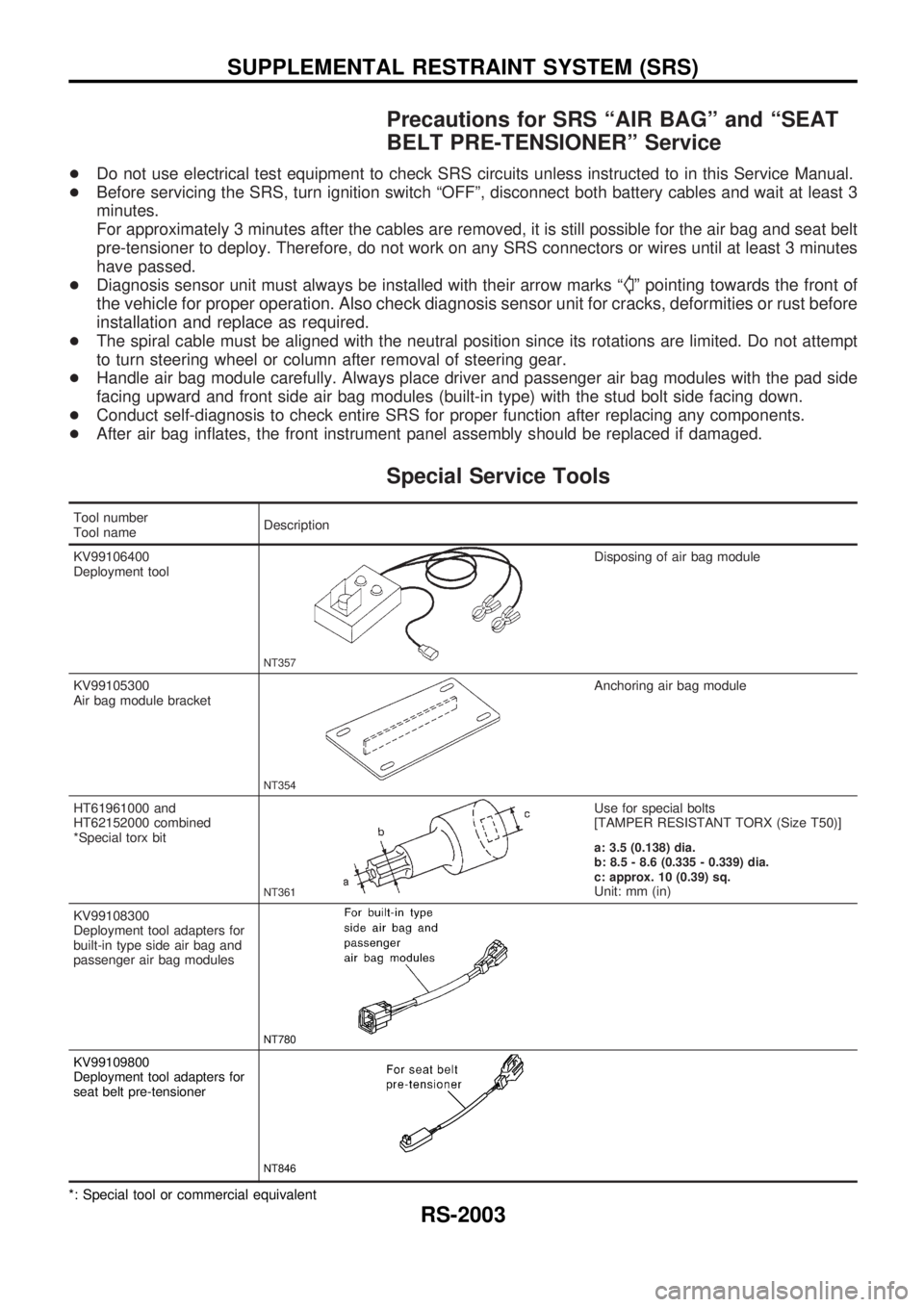
Tool number
Tool nameDescription
KV99106400
Deployment tool
NT357
Disposing of air bag module
KV99105300
Air bag module bracket
NT354
Anchoring air bag module
HT61961000 and
HT62152000 combined
*Special torx bit
NT361
Use for special bolts
[TAMPER RESISTANT TORX (Size T50)]
a: 3.5 (0.138) dia.
b: 8.5 - 8.6 (0.335 - 0.339) dia.
c: approx. 10 (0.39) sq.
Unit: mm (in)
KV99108300
Deployment tool adapters for
built-in type side air bag and
passenger air bag modules
NT780
KV99109800
Deployment tool adapters for
seat belt pre-tensioner
NT846
*: Special tool or commercial equivalent
SUPPLEMENTAL RESTRAINT SYSTEM (SRS)
RS-2003
Page 257 of 273
Removal Ð Driver Air Bag Module and Spiral
Cable
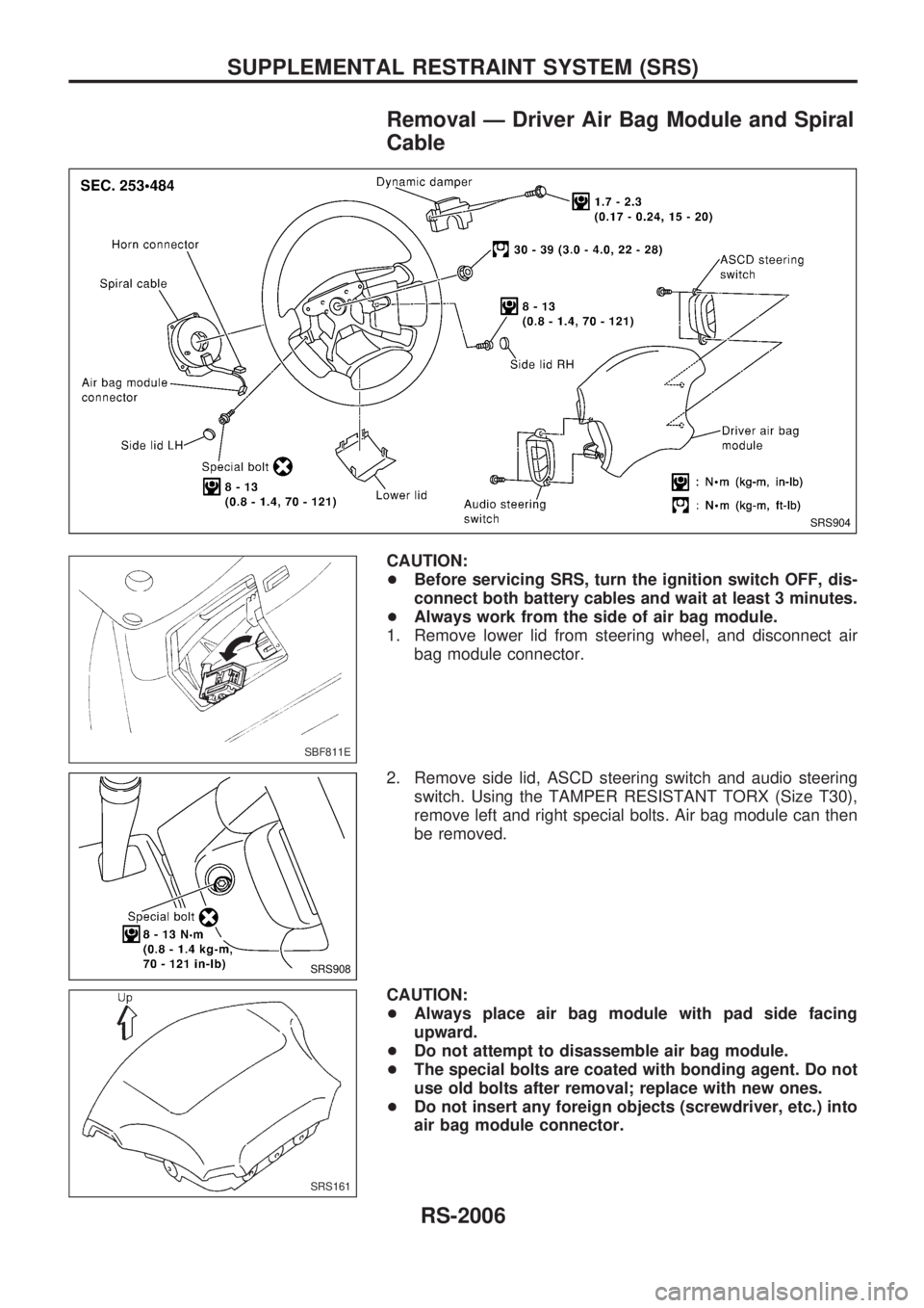
CAUTION:
+Before servicing SRS, turn the ignition switch OFF, dis-
connect both battery cables and wait at least 3 minutes.
+Always work from the side of air bag module.
1. Remove lower lid from steering wheel, and disconnect air
bag module connector.
2. Remove side lid, ASCD steering switch and audio steering
switch. Using the TAMPER RESISTANT TORX (Size T30),
remove left and right special bolts. Air bag module can then
be removed.
CAUTION:
+Always place air bag module with pad side facing
upward.
+Do not attempt to disassemble air bag module.
+The special bolts are coated with bonding agent. Do not
use old bolts after removal; replace with new ones.
+Do not insert any foreign objects (screwdriver, etc.) into
air bag module connector.
SRS904
SBF811E
SRS908
SRS161
SUPPLEMENTAL RESTRAINT SYSTEM (SRS)
RS-2006
Page 258 of 273
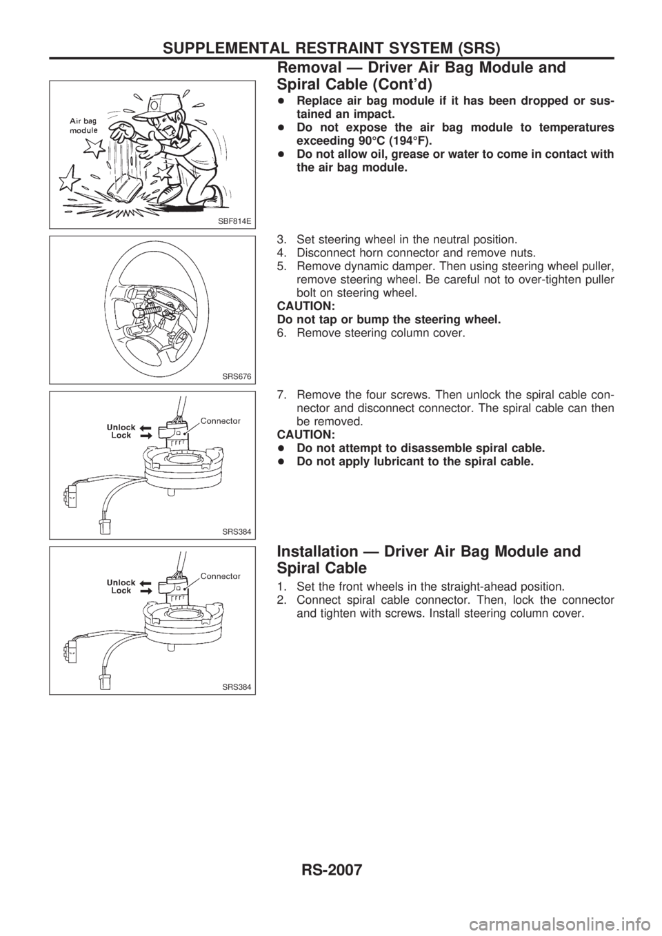
+Replace air bag module if it has been dropped or sus-
tained an impact.
+Do not expose the air bag module to temperatures
exceeding 90ÉC (194ÉF).
+Do not allow oil, grease or water to come in contact with
the air bag module.
3. Set steering wheel in the neutral position.
4. Disconnect horn connector and remove nuts.
5. Remove dynamic damper. Then using steering wheel puller,
remove steering wheel. Be careful not to over-tighten puller
bolt on steering wheel.
CAUTION:
Do not tap or bump the steering wheel.
6. Remove steering column cover.
7. Remove the four screws. Then unlock the spiral cable con-
nector and disconnect connector. The spiral cable can then
be removed.
CAUTION:
+Do not attempt to disassemble spiral cable.
+Do not apply lubricant to the spiral cable.
Installation Ð Driver Air Bag Module and
Spiral Cable
1. Set the front wheels in the straight-ahead position.
2. Connect spiral cable connector. Then, lock the connector
and tighten with screws. Install steering column cover.
SBF814E
SRS676
SRS384
SRS384
SUPPLEMENTAL RESTRAINT SYSTEM (SRS)
Removal Ð Driver Air Bag Module and
Spiral Cable (Cont'd)
RS-2007