2001 NISSAN PATROL fuse
[x] Cancel search: fusePage 49 of 273

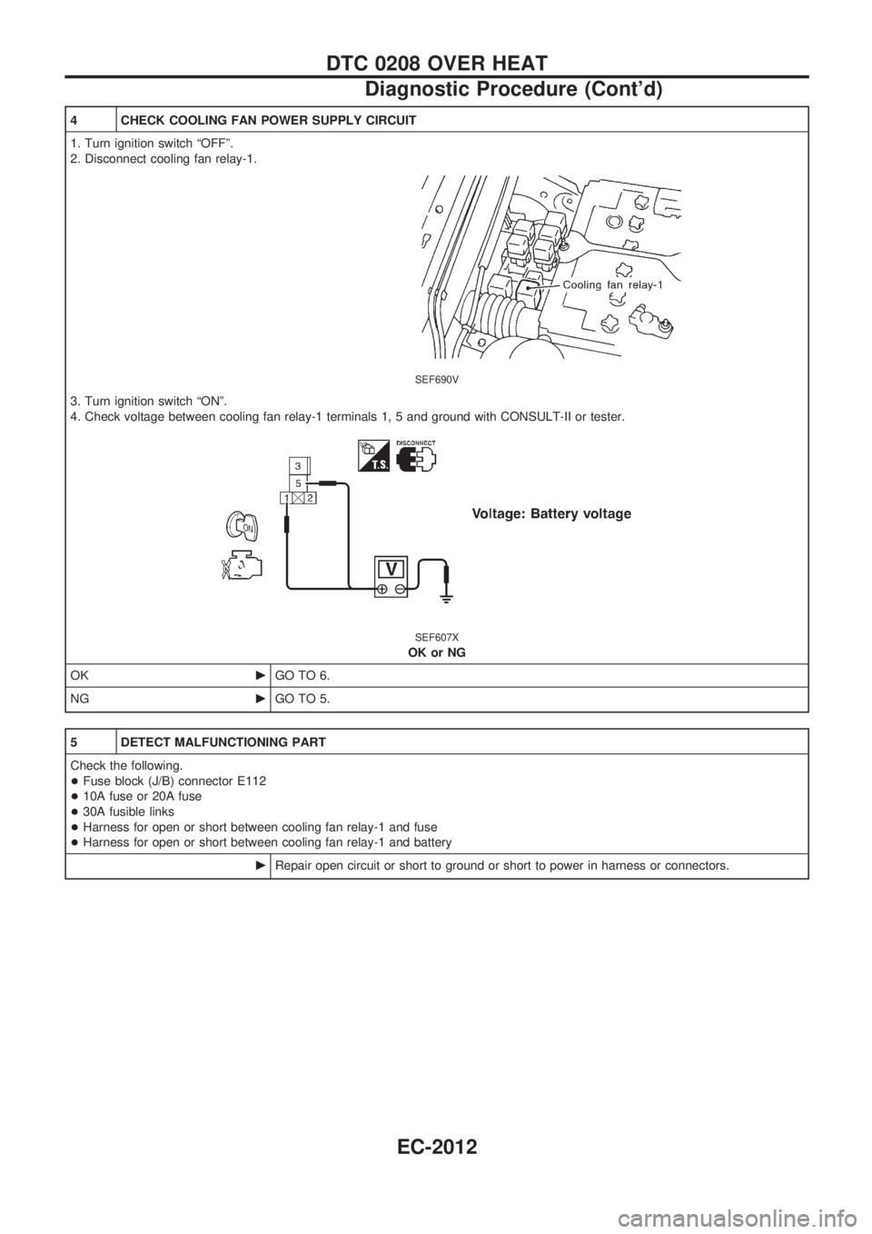
4 CHECK COOLING FAN POWER SUPPLY CIRCUIT
1. Turn ignition switch ªOFFº.
2. Disconnect cooling fan relay-1.
SEF690V
3. Turn ignition switch ªONº.
4. Check voltage between cooling fan relay-1 terminals 1, 5 and ground with CONSULT-II or tester.
SEF607X
OK or NG
OKcGO TO 6.
NGcGO TO 5.
5 DETECT MALFUNCTIONING PART
Check the following.
+Fuse block (J/B) connector E112
+10A fuse or 20A fuse
+30A fusible links
+Harness for open or short between cooling fan relay-1 and fuse
+Harness for open or short between cooling fan relay-1 and battery
cRepair open circuit or short to ground or short to power in harness or connectors.
DTC 0208 OVER HEAT
Diagnostic Procedure (Cont'd)
EC-2012
Page 155 of 273

System Description
WIPER OPERATION
The rear wiper switch is controlled by a ring built into the combination switch.
There are two wiper switch positions:
+ON (LO speed)
+INT (Intermittent)
With the ignition switch in the ON position, power is supplied
+through 10A fuse (No.
18, located in the fuse block)
+to rear wiper motor terminal
V4, and
+to rear wiper amplifier terminal
V5.
Low speed wiper operation
Ground is supplied to rear wiper switch terminalV24through body grounds.
When the rear wiper is placed in the ON position, ground is supplied
+through rear wiper switch terminal
V22
+to rear wiper relay terminalV6.
Then ground is supplied
+to rear wiper motor terminal
V1
+through rear wiper amplifier terminalsV2andV3.
With power and ground supplied, the wiper motor operates.
Auto stop operation
With the rear wiper switch turned OFF, rear wiper motor will continue to operate until wiper arm reaches
rear window base.
When wiper arm is not located at base of rear window with rear wiper switch OFF, ground is supplied
+to rear wiper motor terminal
V1
+through rear wiper amplifier terminalsV2,V7and
+through rear wiper motor terminal
V3, in order to continue rear wiper motor operation at low speed.
Ground is also supplied
+to rear wiper motor terminal
V2
+through body grounds.
When wiper arm reaches base of rear window, rear wiper motor terminals
V3andV4are connected instead
of terminals
V2andV3. Rear wiper motor will then stop wiper arm at the PARK position.
Intermittent operation
The rear wiper motor operates the wiper arm one time at low speed at an interval of approximately 7 sec-
onds.
When the rear wiper switch is placed in the INT position, ground is supplied
+to rear wiper amplifier terminal
V1
+through rear wiper switch terminalV21.
Then the rear wiper motor operates intermittently in the same manner as the low speed wiper operation.
WASHER OPERATION
With the ignition switch in the ACC or ON position, power is supplied
+through 10A fuse (No.
18, located in the fuse block)
+to rear washer motor terminal
V2.
When the ring is turned WASH position, ground is supplied
+to rear washer motor terminal
V1, and
+to rear wiper amplifier terminal
V4
+through terminalV23of rear wiper switch.
With power and ground is supplied, the rear washer motor operates.
The rear wiper motor operates when the ring is turned to WASH position for one second or more and for
approximately 3 seconds after the ring is released. This feature is controlled by the rear wiper amplifier in
the same manner as the low speed wiper operation.
REAR WIPER AND WASHER/WAGON AND HARDTOP MODELS
EL-2078
Page 211 of 273

Terminal Arrangement
CEL271M
FUSE BLOCK Ð Junction Box (J/B)
Page 212 of 273

Terminal Arrangement
CEL272M
FUSE AND FUSIBLE LINK BOX
Page 233 of 273

A
A/T - Wiring diagram ............................. AT-2003
A/T control ............................................. EC-2021
A/T shift lock system ............................. AT-2013
ABS - Wiring diagram ........................... BR-2003
APS - Wiring diagram ........................... EC-2019
AT/C - Wiring diagram .......................... EC-2021
AUDIO - Wiring diagram ....................... EL-2088
Accelerator position sensor .................. EC-2019
Air bag disposal .................................... RS-2009
Air bag ................................................... RS-2003
Air flow meter - See Mass air flow
sensor ................................................ EC-2006
Anti-lock brake system - Wiring
diagram ............................................. BR-2002
Audio ...................................................... EL-2088
B
BACK/L - Wiring diagram ...................... EL-2047
BOOST - Wiring diagram ...................... EC-2029
Back-up lamp ......................................... EL-2047
Bumper, front ....................................... BT-2003
C
CD/CHG - Wiring diagram ..................... EL-2092
CIGAR - Wiring diagram ....................... EL-2085
COOL/F - Wiring diagram ..................... EC-2010
Cigarette lighter ..................................... EL-2085
Clutch cover .......................................... CL-2005
Clutch damper ....................................... CL-2004
Clutch master cylinder ........................... CL-2004
Clutch operating cylinder ....................... CL-2003
Combination meter ................................ EL-2062
Cool box - Wiring diagram .................... HA-2011
Coolant replacement ............................ MA-2003
Cooling circuit (engine) ......................... LC-2002
Cooling fan control ................................ EC-2010
D
DEICER - Wiring diagram ..................... EL-2086
DTRL - Wiring diagram ......................... EL-2037
Daytime light system ............................. EL-2037
Diagnosis sensor unit ........................... RS-2005
E
ECCS-D control module ............. EC-2027, 2028
ECTS - Wiring diagram ......................... EC-2007
EGR - Wiring diagram .......................... EC-2030
EGR volume control valve .................... EC-2030
Electrical unit ......................................... EL-2136Electrical units location .......................... EL-2103
Electronic fuel injection pump .... EC-2018, 2022,
2023, 2024, 2025, 2026, 2031
Engine control circuit diagram .............. EC-2003
Engine coolant temperature sensor
(ECTS) .............................................. EC-2007
Exterior .................................................. BT-2006
F
F/FOG - Wiring diagram ........................ EL-2048
Fluids .................................................... MA-2002
Flywheel (clutch) ................................... CL-2005
Fog lamp, front ...................................... EL-2048
Front bumper ......................................... BT-2003
Front fog lamp ....................................... EL-2048
Front passenger air bag ....................... RS-2003
Fuel gauge ............................................. EL-2062
Fuse block ............................................. EL-2134
Fuse ....................................................... EL-2135
Fusible link ............................................. EL-2135
G
Gauges .................................................. EL-2062
Grease .................................................. MA-2002
Ground distribution ................................ EL-2014
H
H/LAMP - Wiring diagram ..................... EL-2034
HEAT UP - Wiring diagram .................. EC-2035
HLC - Wiring diagram ............................ EL-2083
HORN - Wiring diagram ........................ EL-2084
Harness layout ............................ EL-2106, 2108
Hazard warning lamp ............................ EL-2050
Headlamp wiper ..................................... EL-2083
Headlamp .................................... EL-2034, 2037
Heat up switch ...................................... EC-2035
Hood ...................................................... BT-2003
Horn ....................................................... EL-2084
I
ILL - Wiring diagram .............................. EL-2055
Illumination ............................................. EL-2054
J
Junction box (J/B) .................................. EL-2134
ALPHABETICAL INDEX
IDX-2002
Page 268 of 273
![NISSAN PATROL 2001 Electronic Repair Manual HOW TO ERASE SELF-DIAGNOSIS RESULTS
With CONSULT-II
+ªSELF-DIAG [CURRENT]º
A current Self-diagnosis result is displayed on the CON-
SULT-II screen in real time. After the malfunction is repaired
com NISSAN PATROL 2001 Electronic Repair Manual HOW TO ERASE SELF-DIAGNOSIS RESULTS
With CONSULT-II
+ªSELF-DIAG [CURRENT]º
A current Self-diagnosis result is displayed on the CON-
SULT-II screen in real time. After the malfunction is repaired
com](/manual-img/5/57366/w960_57366-267.png)
HOW TO ERASE SELF-DIAGNOSIS RESULTS
With CONSULT-II
+ªSELF-DIAG [CURRENT]º
A current Self-diagnosis result is displayed on the CON-
SULT-II screen in real time. After the malfunction is repaired
completely, no malfunction is detected on ªSELF-DIAG
[CURRENT]º.
+ªSELF-DIAG [PAST]º
Return to the ªSELF-DIAG [CURRENT]º CONSULT-II screen
by pushing ªBACKº key of CONSULT-II and select ªSELF-
DIAG [CURRENT]º in ªSELECT DIAG MODEº. Touch
ªERASEº in ªSELF-DIAG [CURRENT]º mode.
NOTE:
If the memory of the malfunction in ªSELF-DIAG [PAST]º is
not erased, the User mode shows the system malfunction by
the operation of the warning lamp even if the malfunction is
repaired completely.
+ªTROUBLE DIAG RECORDº
The memory of ªTROUBLE DIAG RECORDº cannot be
erased.
Without CONSULT-II
After a malfunction is repaired, return Diagnosis mode to User
mode by switching the ignition ªOFFº for at least 1 second, then
back ªONº. At that time, the self-diagnostic result is cleared.
How to Perform Trouble Diagnoses for Quick
and Accurate Repair
A good understanding of the malfunction conditions can make troubleshooting faster and more accurate.
In general, each customer feels differently about a malfunction. It is important to fully understand the symp-
toms or conditions for a customer complaint.
INFORMATION FROM CUSTOMER
WHAT ........ Vehicle model
WHEN ....... Date, Frequencies
WHERE ..... Road conditions
HOW .......... Operating conditions, Symptoms
PRELIMINARY CHECK
Check that the following parts are in good order.
+Battery [Refer to EL section (ªBATTERYº) of Service Manual.]
+Fuse [Refer to EL section (ªFuseº, ªPOWER SUPPLY ROUTINGº) of Service Manual.]
+System component-to-harness connections
SRS701
TROUBLE DIAGNOSES Ð Supplemental Restraint System (SRS)
Trouble Diagnoses Introduction (Cont'd)
RS-2017