2001 NISSAN PATROL engine
[x] Cancel search: enginePage 1 of 273
Edition: July 2001
Release: September 2001 (01)
Publication No.: SM1E-Y61BE0E
Reference No.: 7711345090GENERAL INFORMATIONGI
MAINTENANCEMA
ENGINE MECHANICALEM
ENGINE LUBRICATION &
COOLING SYSTEMSLC
ENGINE CONTROL SYSTEMEC
ACCELERATOR CONTROL,
FUEL & EXHAUST SYSTEMFE
CLUTCHCL
MANUAL TRANSMISSIONMT
AUTOMATIC TRANSMISSIONAT
TRANSFERTF
PROPELLER SHAFT &
DIFFERENTIAL CARRIERPD
FRONT AXLE & FRONT SUSPENSIONFA
REAR AXLE & REAR SUSPENSIONRA
BRAKE SYSTEMBR
STEERING SYSTEMST
RESTRAINT SYSTEMRS
BODY & TRIMBT
HEATER & AIR CONDITIONERHA
ELECTRICAL SYSTEMEL
ALPHABETICAL INDEXIDX
PATROL GR
MODEL Y61 SERIES
NISSAN EUROPE S.A.S.
2001 NISSAN EUROPE S.A.S.
Produced in The Netherlands
Not to be reproduced in whole or in part
without the prior written permission of
Nissan Europe S.A.S., Paris, France.
QUICK REFERENCE INDEX
Page 2 of 273
FOREWORD
This manual contains maintenance and repair procedures for NISSAN
PATROL GR,modelY61 series.
In order to assure your safety and the efficient functioning of the vehicle,
this manual should be read thoroughly. It is especially important that the
PRECAUTIONS in the GI section be completely understood before starting
any repair task.
All information in this manual is based on the latest product information
at the time of publication. The right is reserved to make changes in speci-
®cations and methods at any time without notice.
IMPORTANT SAFETY NOTICE
The proper performance of service is essential for both the safety of the
technician and the efficient functioning of the vehicle.
The service methods in this Service Manual are described in such a man-
ner that the service may be performed safely and accurately.
Service varies with the procedures used, the skills of the technician and the
tools and parts available. Accordingly, anyone using service procedures,
tools or parts which are not speci®cally recommended by NISSAN must
®rst completely satisfy himself that neither his safety nor the vehicle's
safety will be jeopardized by the service method selected.
NISSAN EUROPE S.A.S.
Service Engineering SectionParis, France
Page 27 of 273
Body Front End
+When removing or installing hood, place a cloth or other padding on front fender panel and cowl top.
This prevents vehicle body from being scratched.
+Bumper fascia is made of plastic. Do not use excessive force and be sure to keep oil away from it.
+Hood adjustment: Adjust at hinge portion.
+Hood lock adjustment: After adjusting, check hood lock control operation. Apply a coat of grease to hood
locks engaging mechanism.
+Hood opener: Do not attempt to bend cable forcibly. Doing so increases effort required to unlock hood.
REMOVAL Ð Front bumper assembly
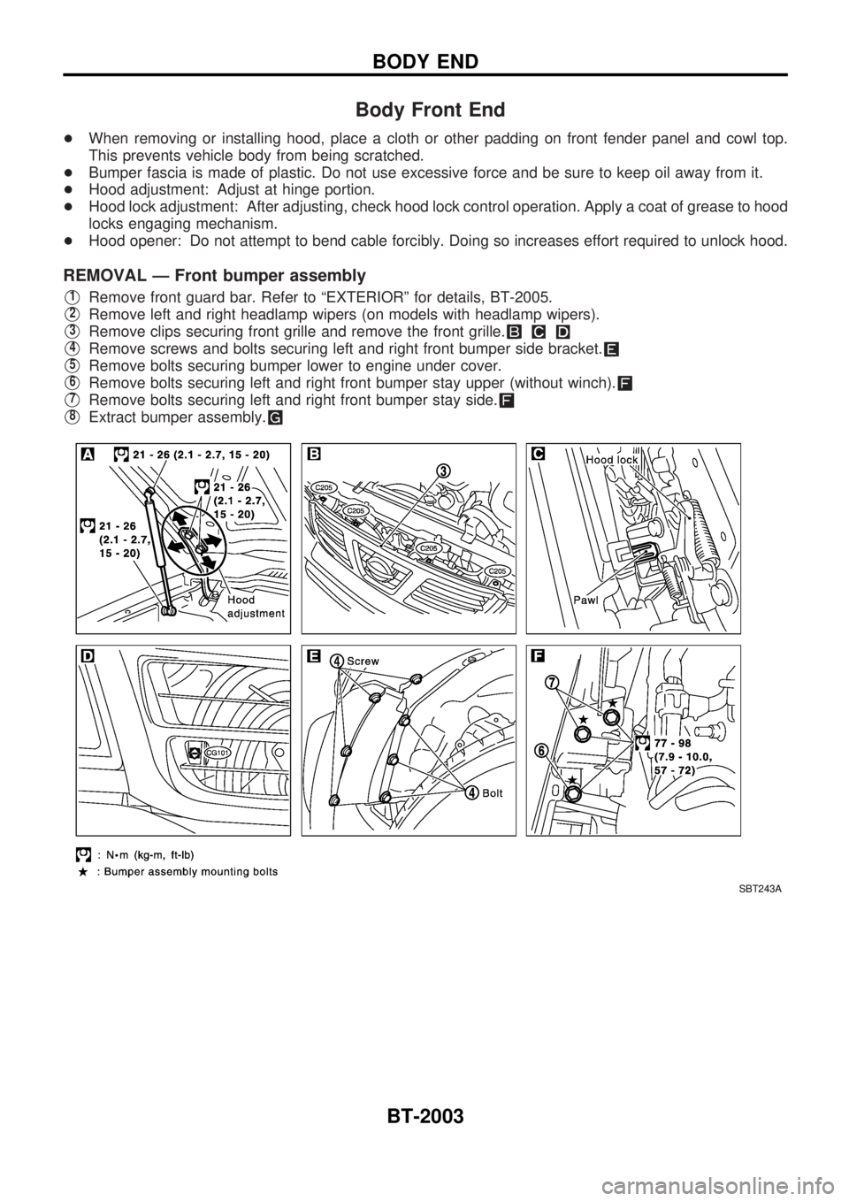
V1Remove front guard bar. Refer to ªEXTERIORº for details, BT-2005.
V2Remove left and right headlamp wipers (on models with headlamp wipers).
V3Remove clips securing front grille and remove the front grille.
V4Remove screws and bolts securing left and right front bumper side bracket.
V5Remove bolts securing bumper lower to engine under cover.
V6Remove bolts securing left and right front bumper stay upper (without winch).
V7Remove bolts securing left and right front bumper stay side.
V8Extract bumper assembly.
SBT243A
BODY END
BT-2003
Page 38 of 273
ENGINE CONTROL SYSTEM
SECTION
EC
CONTENTS
ENGINE AND EMISSION CONTROL OVERALL
SYSTEM............................................................... 2003
Circuit Diagram ................................................ 2003
TROUBLE DIAGNOSIS FOR POWER
SUPPLY............................................................... 2004
Main Power Supply and Ground Circuit .......... 2004
DTC 0102 MASS AIR FLOW SEN...................... 2006
Wiring Diagram ................................................ 2006
DTC 0103 COOLANT TEMP SEN...................... 2007
Wiring Diagram ................................................ 2007
DTC 0104 VEHICLE SPEED SEN...................... 2008
Wiring Diagram ................................................ 2008
DTC 0203 ACCEL POS SW (F/C)...................... 2009
Wiring Diagram ................................................ 2009
DTC 0208 OVER HEAT....................................... 2010
Wiring Diagram ................................................ 2010
Diagnostic Procedure....................................... 2011
Component Inspection ..................................... 2016
Main 12 Causes of Overheating ...................... 2017
DTC 0402 P9zFUEL TEMP SEN......................... 2018
Wiring Diagram ................................................ 2018
DTC 0403 ACCEL POS SENSOR...................... 2019
Wiring Diagram ................................................ 2019
DTC 0504 A/T COMM LINE................................ 2021
Wiring Diagram ................................................ 2021
DTC 0701 P1zCAM POS SEN............................. 2022
Wiring Diagram ................................................ 2022
DTC 0702 P2zTDC PULSE SIG........................... 2023
Wiring Diagram ................................................ 2023
DTC 0703 P3zPUMP COMM LINE...................... 2024
Wiring Diagram ................................................ 2024
DTC 0704 P4zSPILL/V CIRC, DTC 0706
P6zSPILL VALVE................................................. 2025Wiring Diagram ................................................ 2025
DTC 0707 P7zF/INJ TIMG FB.............................. 2026
Wiring Diagram ................................................ 2026
DTC 0807 ECM 14............................................... 2027
Wiring Diagram ................................................ 2027
DTC 0902 ECM RLY........................................... 2028
Wiring Diagram ................................................ 2028
DTC 0905 TURBO PRESSURE.......................... 2029
Wiring Diagram ................................................ 2029
DTC 1003 EGR VOLUME CONT/V..................... 2030
Wiring Diagram ................................................ 2030
DTC 1004 FUEL CUT SYSTEM1........................ 2031
Wiring Diagram ................................................ 2031
GLOW CONTROL SYSTEM............................... 2032
Wiring Diagram ................................................ 2032
START SIGNAL................................................... 2033
Wiring Diagram ................................................ 2033
PARK/NEUTRAL POSITION (PNP) SWITCH.... 2034
Wiring Diagram ................................................ 2034
HEAT UP SWITCH.............................................. 2035
Wiring Diagram ................................................ 2035
SWIRL CONTROL VALVE CONTROL
SOLENOID VALVE.............................................. 2036
Wiring Diagram ................................................ 2036
INTAKE AIR CONTROL VALVE CONTROL
SOLENOID VALVE.............................................. 2037
Wiring Diagram ................................................ 2037
AIR CONDITIONER CONTROL.......................... 2038
Wiring Diagram ................................................ 2038
MI (MIL) & DATA LINK CONNECTORS............ 2039
Wiring Diagram ................................................ 2039
EC
Page 40 of 273

Circuit Diagram
TEC095M
ENGINE AND EMISSION CONTROL OVERALL SYSTEM
EC-2003
Page 48 of 273
Diagnostic Procedure
1 INSPECTION START
Do you have CONSULT-II?
Yes or No
YescGO TO 2.
NocGO TO 3.
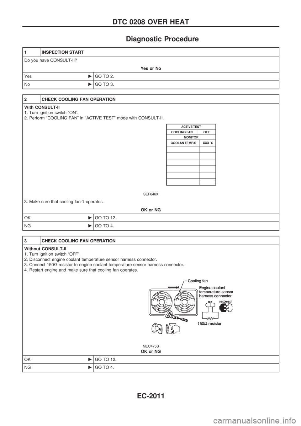
2 CHECK COOLING FAN OPERATION
With CONSULT-II
1. Turn ignition switch ªONº.
2. Perform ªCOOLING FANº in ªACTIVE TESTº mode with CONSULT-II.
SEF646X
3. Make sure that cooling fan-1 operates.
OK or NG
OKcGO TO 12.
NGcGO TO 4.
3 CHECK COOLING FAN OPERATION
Without CONSULT-II
1. Turn ignition switch ªOFFº.
2. Disconnect engine coolant temperature sensor harness connector.
3. Connect 150Wresistor to engine coolant temperature sensor harness connector.
4. Restart engine and make sure that cooling fan operates.
MEC475B
OK or NG
OKcGO TO 12.
NGcGO TO 4.
DTC 0208 OVER HEAT
EC-2011
Page 53 of 273
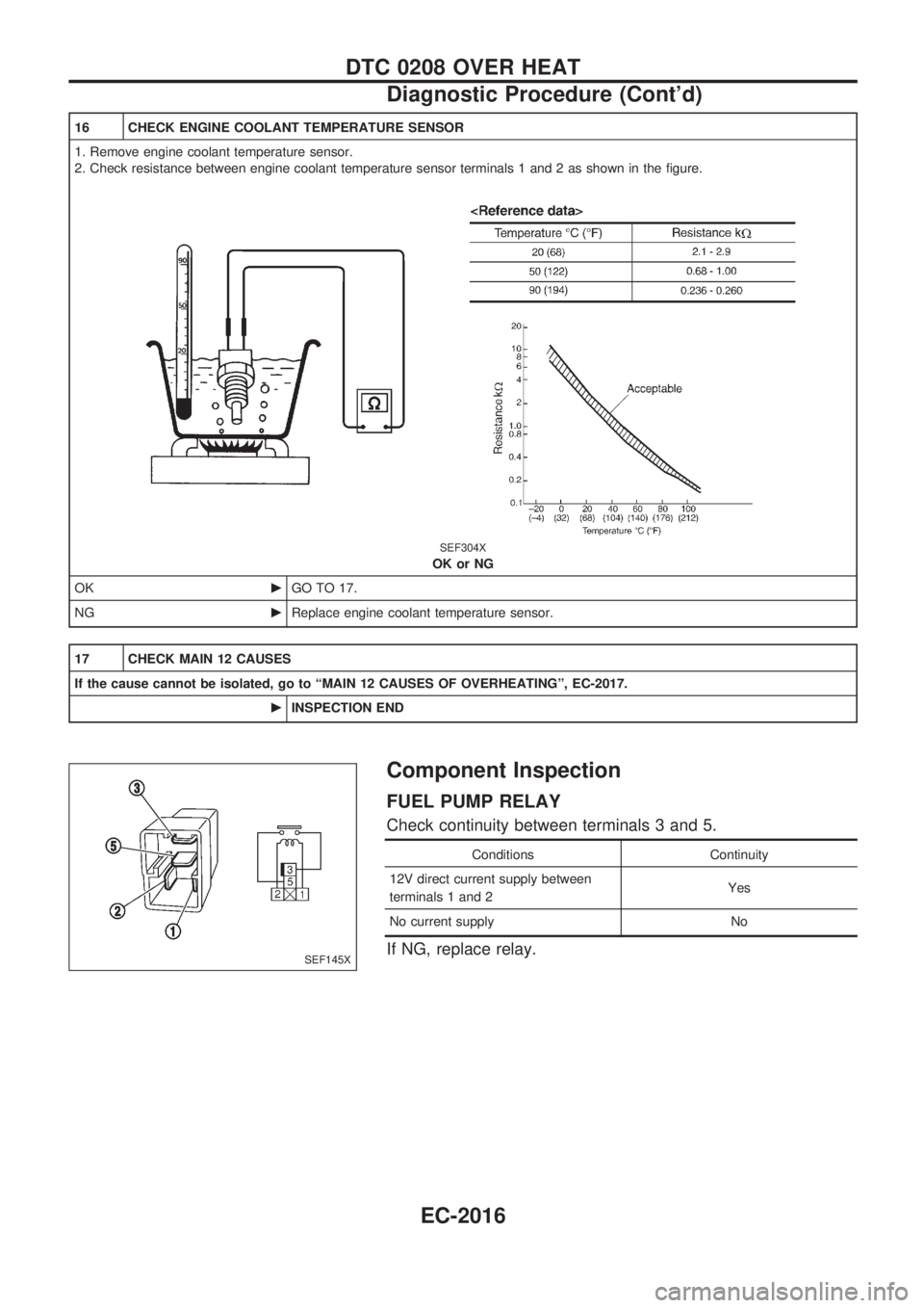
16 CHECK ENGINE COOLANT TEMPERATURE SENSOR
1. Remove engine coolant temperature sensor.
2. Check resistance between engine coolant temperature sensor terminals 1 and 2 as shown in the figure.
SEF304X
OK or NG
OKcGO TO 17.
NGcReplace engine coolant temperature sensor.
17 CHECK MAIN 12 CAUSES
If the cause cannot be isolated, go to ªMAIN 12 CAUSES OF OVERHEATINGº, EC-2017.
cINSPECTION END
Component Inspection
FUEL PUMP RELAY
Check continuity between terminals 3 and 5.
Conditions Continuity
12V direct current supply between
terminals 1 and 2Yes
No current supply No
If NG, replace relay.SEF145X
DTC 0208 OVER HEAT
Diagnostic Procedure (Cont'd)
EC-2016
Page 54 of 273
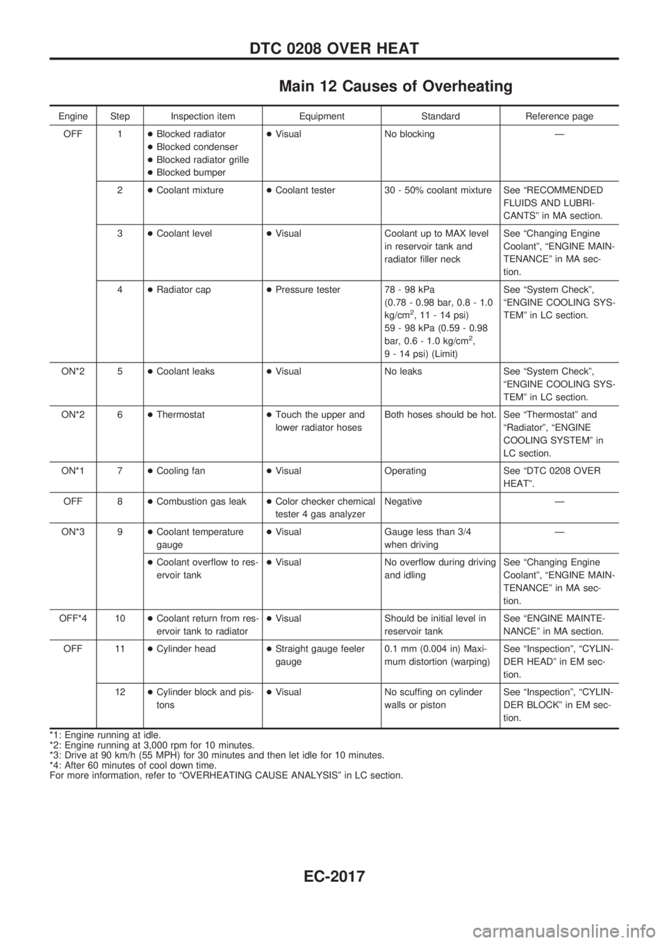
Main 12 Causes of Overheating
Engine Step Inspection item Equipment Standard Reference page
OFF 1+Blocked radiator
+Blocked condenser
+Blocked radiator grille
+Blocked bumper+Visual No blocking Ð
2+Coolant mixture+Coolant tester 30 - 50% coolant mixture See ªRECOMMENDED
FLUIDS AND LUBRI-
CANTSº in MA section.
3+Coolant level+Visual Coolant up to MAX level
in reservoir tank and
radiator filler neckSee ªChanging Engine
Coolantº, ªENGINE MAIN-
TENANCEº in MA sec-
tion.
4+Radiator cap+Pressure tester 78 - 98 kPa
(0.78 - 0.98 bar, 0.8 - 1.0
kg/cm
2, 11 - 14 psi)
59 - 98 kPa (0.59 - 0.98
bar, 0.6 - 1.0 kg/cm
2,
9 - 14 psi) (Limit)See ªSystem Checkº,
ªENGINE COOLING SYS-
TEMº in LC section.
ON*2 5+Coolant leaks+Visual No leaks See ªSystem Checkº,
ªENGINE COOLING SYS-
TEMº in LC section.
ON*2 6+Thermostat+Touch the upper and
lower radiator hosesBoth hoses should be hot. See ªThermostatº and
ªRadiatorº, ªENGINE
COOLING SYSTEMº in
LC section.
ON*1 7+Cooling fan+Visual Operating See ªDTC 0208 OVER
HEATº.
OFF 8+Combustion gas leak+Color checker chemical
tester 4 gas analyzerNegative Ð
ON*3 9+Coolant temperature
gauge+Visual Gauge less than 3/4
when drivingÐ
+Coolant overflow to res-
ervoir tank+Visual No overflow during driving
and idlingSee ªChanging Engine
Coolantº, ªENGINE MAIN-
TENANCEº in MA sec-
tion.
OFF*4 10+Coolant return from res-
ervoir tank to radiator+Visual Should be initial level in
reservoir tankSee ªENGINE MAINTE-
NANCEº in MA section.
OFF 11+Cylinder head+Straight gauge feeler
gauge0.1 mm (0.004 in) Maxi-
mum distortion (warping)See ªInspectionº, ªCYLIN-
DER HEADº in EM sec-
tion.
12+Cylinder block and pis-
tons+Visual No scuffing on cylinder
walls or pistonSee ªInspectionº, ªCYLIN-
DER BLOCKº in EM sec-
tion.
*1: Engine running at idle.
*2: Engine running at 3,000 rpm for 10 minutes.
*3: Drive at 90 km/h (55 MPH) for 30 minutes and then let idle for 10 minutes.
*4: After 60 minutes of cool down time.
For more information, refer to ªOVERHEATING CAUSE ANALYSISº in LC section.
DTC 0208 OVER HEAT
EC-2017