Page 257 of 3051
RemovalNLBR0123
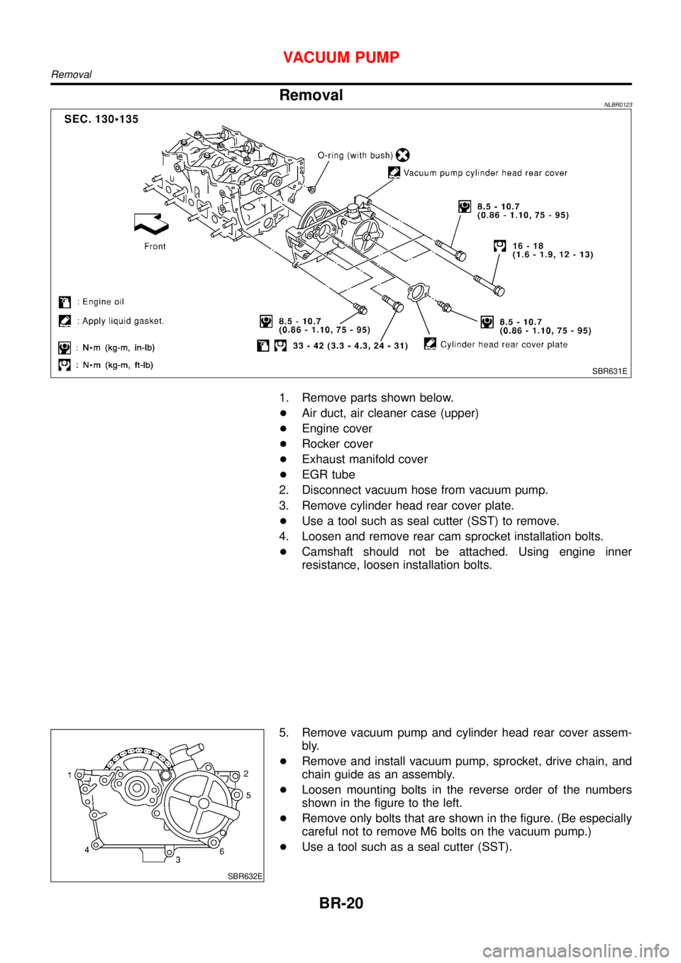
SBR631E
1. Remove parts shown below.
+Air duct, air cleaner case (upper)
+Engine cover
+Rocker cover
+Exhaust manifold cover
+EGR tube
2. Disconnect vacuum hose from vacuum pump.
3. Remove cylinder head rear cover plate.
+Use a tool such as seal cutter (SST) to remove.
4. Loosen and remove rear cam sprocket installation bolts.
+Camshaft should not be attached. Using engine inner
resistance, loosen installation bolts.
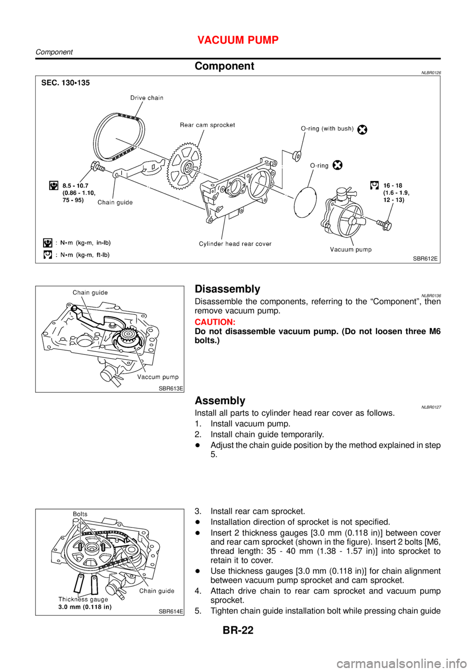
SBR632E
5. Remove vacuum pump and cylinder head rear cover assem-
bly.
+Remove and install vacuum pump, sprocket, drive chain, and
chain guide as an assembly.
+Loosen mounting bolts in the reverse order of the numbers
shown in the figure to the left.
+Remove only bolts that are shown in the figure. (Be especially
careful not to remove M6 bolts on the vacuum pump.)
+Use a tool such as a seal cutter (SST).
VACUUM PUMP
Removal
BR-20
Page 259 of 3051
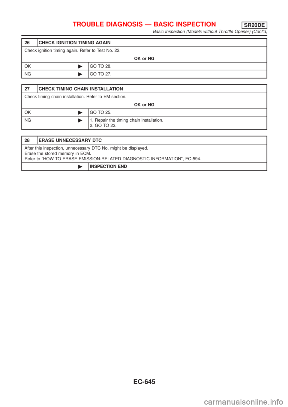
ComponentNLBR0126
SBR612E
SBR613E
DisassemblyNLBR0136Disassemble the components, referring to the“Component”, then
remove vacuum pump.
CAUTION:
Do not disassemble vacuum pump. (Do not loosen three M6
bolts.)
AssemblyNLBR0127Install all parts to cylinder head rear cover as follows.
1. Install vacuum pump.
2. Install chain guide temporarily.
+Adjust the chain guide position by the method explained in step
5.
SBR614E
3. Install rear cam sprocket.
+Installation direction of sprocket is not specified.
+Insert 2 thickness gauges [3.0 mm (0.118 in)] between cover
and rear cam sprocket (shown in the figure). Insert 2 bolts [M6,
thread length: 35 - 40 mm (1.38 - 1.57 in)] into sprocket to
retain it to cover.
+Use thickness gauges [3.0 mm (0.118 in)] for chain alignment
between vacuum pump sprocket and cam sprocket.
4. Attach drive chain to rear cam sprocket and vacuum pump
sprocket.
5. Tighten chain guide installation bolt while pressing chain guide
VACUUM PUMP
Component
BR-22
Page 545 of 3051
19 CHECK ECM FUNCTION
1. Substitute another known-good ECM to check ECM function. (ECM may be the cause of a problem, but this is rarely
the case.)
2. Perform initialization of NATS system and registration of NATS ignition key IDs. Refer to ªNATS (Nissan Anti-Theft
system)º, EC-72
©GO TO 14.
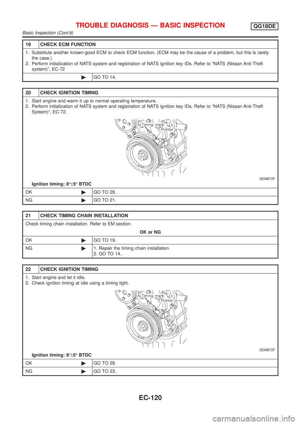
20 CHECK IGNITION TIMING
1. Start engine and warm it up to normal operating temperature.
2. Perform initialization of NATS system and registration of NATS ignition key IDs. Refer to ªNATS (Nissan Anti-Theft
System)º, EC-72.
SEM872F
Ignition timing: 8ɱ5É BTDC
OK©GO TO 28.
NG©GO TO 21.
21 CHECK TIMING CHAIN INSTALLATION
Check timing chain installation. Refer to EM section.
OK or NG
OK©GO TO 19.
NG©1. Repair the timing chain installation.
2. GO TO 14..
22 CHECK IGNITION TIMING
1. Start engine and let it idle.
2. Check ignition timing at idle using a timing light.
SEM872F
Ignition timing: 8ɱ5É BTDC
OK©GO TO 28.
NG©GO TO 23.
TROUBLE DIAGNOSIS Ð BASIC INSPECTIONQG18DE
Basic Inspection (Cont'd)
EC-120
Page 546 of 3051
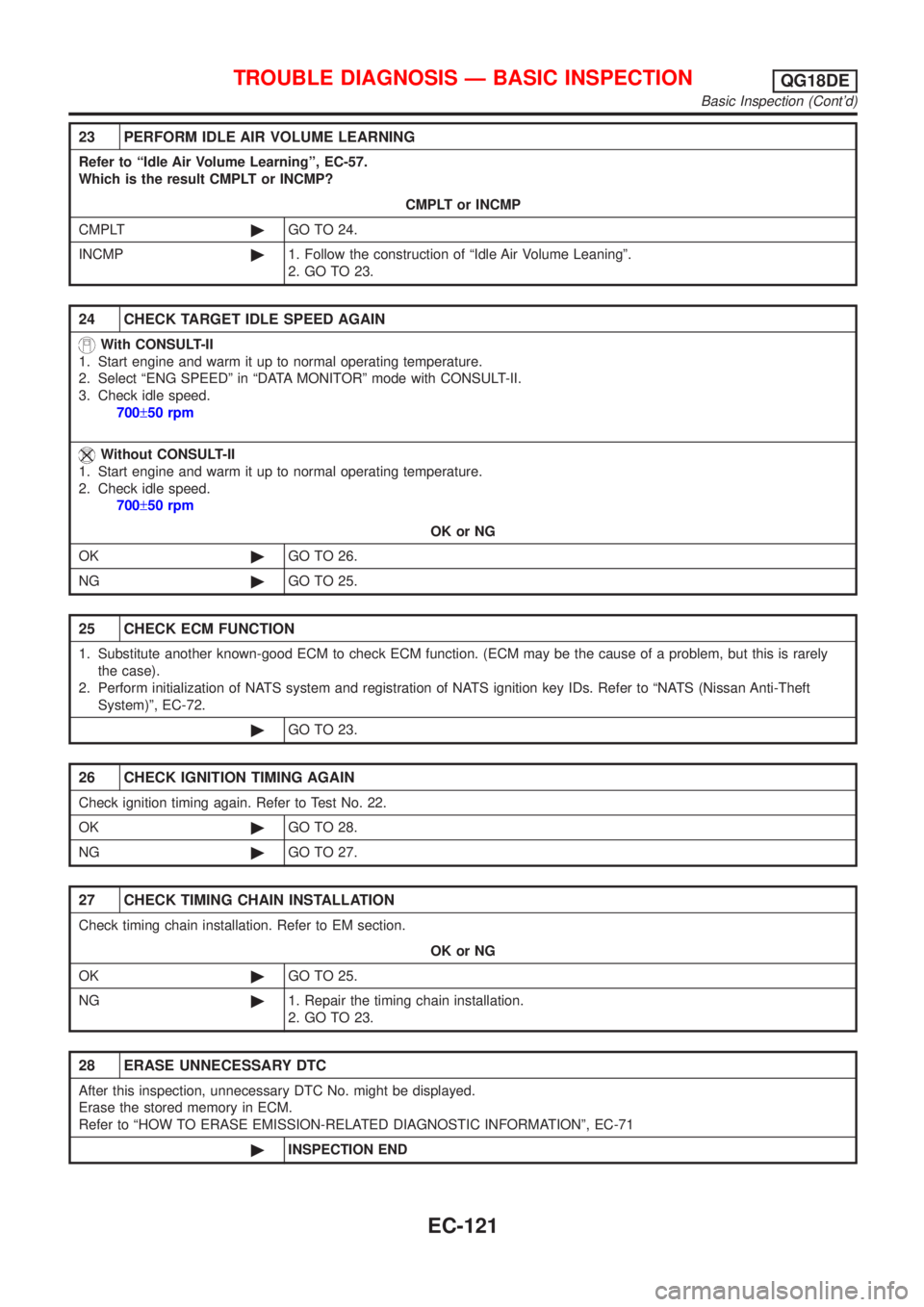
23 PERFORM IDLE AIR VOLUME LEARNING
Refer to ªIdle Air Volume Learningº, EC-57.
Which is the result CMPLT or INCMP?
CMPLT or INCMP
CMPLT©GO TO 24.
INCMP©1. Follow the construction of ªIdle Air Volume Leaningº.
2. GO TO 23.
24 CHECK TARGET IDLE SPEED AGAIN
With CONSULT-II
1. Start engine and warm it up to normal operating temperature.
2. Select ªENG SPEEDº in ªDATA MONITORº mode with CONSULT-II.
3. Check idle speed.
700±50 rpm
Without CONSULT-II
1. Start engine and warm it up to normal operating temperature.
2. Check idle speed.
700±50 rpm
OK or NG
OK©GO TO 26.
NG©GO TO 25.
25 CHECK ECM FUNCTION
1. Substitute another known-good ECM to check ECM function. (ECM may be the cause of a problem, but this is rarely
the case).
2. Perform initialization of NATS system and registration of NATS ignition key IDs. Refer to ªNATS (Nissan Anti-Theft
System)º, EC-72.
©GO TO 23.
26 CHECK IGNITION TIMING AGAIN
Check ignition timing again. Refer to Test No. 22.
OK©GO TO 28.
NG©GO TO 27.
27 CHECK TIMING CHAIN INSTALLATION
Check timing chain installation. Refer to EM section.
OK or NG
OK©GO TO 25.
NG©1. Repair the timing chain installation.
2. GO TO 23.
28 ERASE UNNECESSARY DTC
After this inspection, unnecessary DTC No. might be displayed.
Erase the stored memory in ECM.
Refer to ªHOW TO ERASE EMISSION-RELATED DIAGNOSTIC INFORMATIONº, EC-71
©INSPECTION END
TROUBLE DIAGNOSIS Ð BASIC INSPECTIONQG18DE
Basic Inspection (Cont'd)
EC-121
Page 552 of 3051
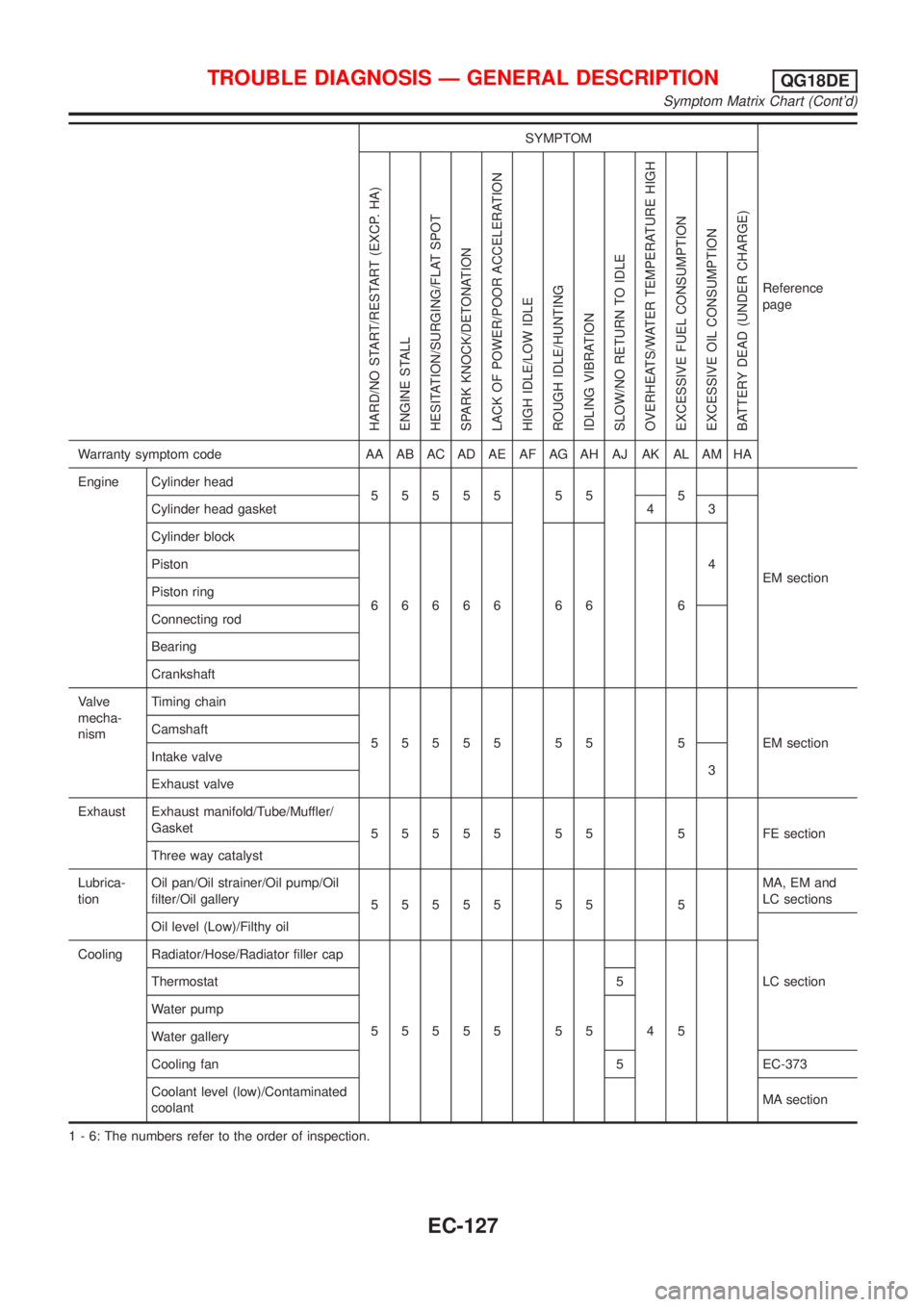
SYMPTOM
Reference
page
HARD/NO START/RESTART (EXCP. HA)
ENGINE STALL
HESITATION/SURGING/FLAT SPOT
SPARK KNOCK/DETONATION
LACK OF POWER/POOR ACCELERATION
HIGH IDLE/LOW IDLE
ROUGH IDLE/HUNTING
IDLING VIBRATION
SLOW/NO RETURN TO IDLE
OVERHEATS/WATER TEMPERATURE HIGH
EXCESSIVE FUEL CONSUMPTION
EXCESSIVE OIL CONSUMPTION
BATTERY DEAD (UNDER CHARGE)
Warranty symptom code AA AB AC AD AE AF AG AH AJ AK AL AM HA
Engine Cylinder head
55555 55 5
EM section Cylinder head gasket 4 3
Cylinder block
66666 66 64 Piston
Piston ring
Connecting rod
Bearing
Crankshaft
Valve
mecha-
nismTiming chain
55555 55 5 EMsection Camshaft
Intake valve
3
Exhaust valve
Exhaust Exhaust manifold/Tube/Muffler/
Gasket
55555 55 5 FEsection
Three way catalyst
Lubrica-
tionOil pan/Oil strainer/Oil pump/Oil
filter/Oil gallery
55555 55 5MA, EM and
LC sections
Oil level (Low)/Filthy oil
LC section Cooling Radiator/Hose/Radiator filler cap
55555 55 45 Thermostat 5
Water pump
Water gallery
Cooling fan 5 EC-373
Coolant level (low)/Contaminated
coolantMA section
1 - 6: The numbers refer to the order of inspection.
TROUBLE DIAGNOSIS Ð GENERAL DESCRIPTIONQG18DE
Symptom Matrix Chart (Cont'd)
EC-127
Page 1068 of 3051
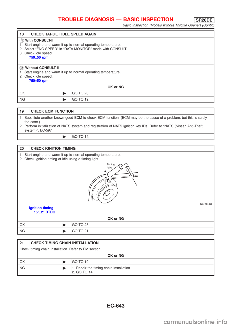
18 CHECK TARGET IDLE SPEED AGAIN
With CONSULT-II
1. Start engine and warm it up to normal operating temperature.
2. Select ªENG SPEEDº in ªDATA MONITORº mode with CONSULT-II.
3. Check idle speed.
750±50 rpm
Without CONSULT-II
1. Start engine and warm it up to normal operating temperature.
2. Check idle speed.
750±50 rpm
OK or NG
OK©GO TO 20.
NG©GO TO 19.
19 CHECK ECM FUNCTION
1. Substitute another known-good ECM to check ECM function. (ECM may be the cause of a problem, but this is rarely
the case.)
2. Perform initialization of NATS system and registration of NATS ignition key IDs. Refer to ªNATS (Nissan Anti-Theft
system)º, EC-597
©GO TO 14.
20 CHECK IGNITION TIMING
1. Start engine and warm it up to normal operating temperature.
2. Check ignition timing at idle using a timing light.
SEF984U
Ignition timing
15ɱ2É BTDC
OK or NG
OK©GO TO 28.
NG©GO TO 21.
21 CHECK TIMING CHAIN INSTALLATION
Check timing chain installation. Refer to EM section.
OK or NG
OK©GO TO 19.
NG©1. Repair the timing chain installation.
2. GO TO 14.
TROUBLE DIAGNOSIS Ð BASIC INSPECTIONSR20DE
Basic Inspection (Models without Throttle Opener) (Cont'd)
EC-643
Page 1070 of 3051
26 CHECK IGNITION TIMING AGAIN
Check ignition timing again. Refer to Test No. 22.
OK or NG
OK©GO TO 28.
NG©GO TO 27.
27 CHECK TIMING CHAIN INSTALLATION
Check timing chain installation. Refer to EM section.
OK or NG
OK©GO TO 25.
NG©1. Repair the timing chain installation.
2. GO TO 23.
28 ERASE UNNECESSARY DTC
After this inspection, unnecessary DTC No. might be displayed.
Erase the stored memory in ECM.
Refer to ªHOW TO ERASE EMISSION-RELATED DIAGNOSTIC INFORMATIONº, EC-594.
©INSPECTION END
TROUBLE DIAGNOSIS Ð BASIC INSPECTIONSR20DE
Basic Inspection (Models without Throttle Opener) (Cont'd)
EC-645
Page 1076 of 3051
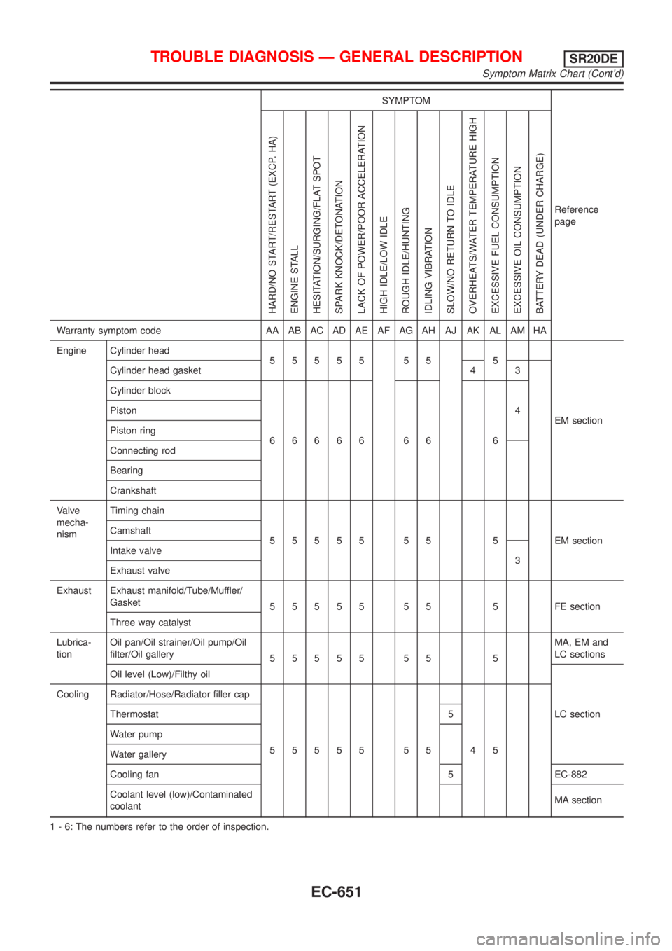
SYMPTOM
Reference
page
HARD/NO START/RESTART (EXCP. HA)
ENGINE STALL
HESITATION/SURGING/FLAT SPOT
SPARK KNOCK/DETONATION
LACK OF POWER/POOR ACCELERATION
HIGH IDLE/LOW IDLE
ROUGH IDLE/HUNTING
IDLING VIBRATION
SLOW/NO RETURN TO IDLE
OVERHEATS/WATER TEMPERATURE HIGH
EXCESSIVE FUEL CONSUMPTION
EXCESSIVE OIL CONSUMPTION
BATTERY DEAD (UNDER CHARGE)
Warranty symptom code AA AB AC AD AE AF AG AH AJ AK AL AM HA
Engine Cylinder head
55555 55 5
EM section Cylinder head gasket 4 3
Cylinder block
66666 66 64 Piston
Piston ring
Connecting rod
Bearing
Crankshaft
Valve
mecha-
nismTiming chain
55555 55 5 EMsection Camshaft
Intake valve
3
Exhaust valve
Exhaust Exhaust manifold/Tube/Muffler/
Gasket
55555 55 5 FEsection
Three way catalyst
Lubrica-
tionOil pan/Oil strainer/Oil pump/Oil
filter/Oil gallery
55555 55 5MA, EM and
LC sections
Oil level (Low)/Filthy oil
LC section Cooling Radiator/Hose/Radiator filler cap
55555 55 45 Thermostat 5
Water pump
Water gallery
Cooling fan 5 EC-882
Coolant level (low)/Contaminated
coolantMA section
1 - 6: The numbers refer to the order of inspection.
TROUBLE DIAGNOSIS Ð GENERAL DESCRIPTIONSR20DE
Symptom Matrix Chart (Cont'd)
EC-651