2001 NISSAN ALMERA TINO engine coolant
[x] Cancel search: engine coolantPage 547 of 3051
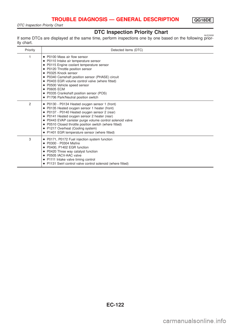
DTC Inspection Priority ChartNLEC0039If some DTCs are displayed at the same time, perform inspections one by one based on the following prior-
ity chart.
Priority Detected items (DTC)
1+P0100 Mass air flow sensor
+P0110 Intake air temperature sensor
+P0115 Engine coolant temperature sensor
+P0120 Throttle position sensor
+P0325 Knock sensor
+P0340 Camshaft position sensor (PHASE) circuit
+P0403 EGR volume control valve (where fitted)
+P0500 Vehicle speed sensor
+P0605 ECM
+P0335 Crankshaft position sensor (POS)
+P1706 Park/Neutral position switch
2+P0130 - P0134 Heated oxygen sensor 1 (front)
+P0135 Heated oxygen sensor 1 heater (front)
+P0137 - P0140 Heated oxygen sensor 2 (rear)
+P0141 Heated oxygen sensor 2 heater (rear)
+P0443 EVAP canister purge volume control solenoid valve
+P0510 Closed throttle position switch (where fitted)
+P1217 Overheat (Cooling system)
+P1401 EGR temperature sensor (where fitted)
3+P0171, P0172 Fuel injection system function
+P0300 - P0304 Misfire
+P0400, P1402 EGR function
+P0420 Three way catalyst function
+P0505 IACV-AAC valve
+P 1111Intake valve timing control
+P1131 Swirl control valve control solenoid (where fitted)
TROUBLE DIAGNOSIS Ð GENERAL DESCRIPTIONQG18DE
DTC Inspection Priority Chart
EC-122
Page 548 of 3051
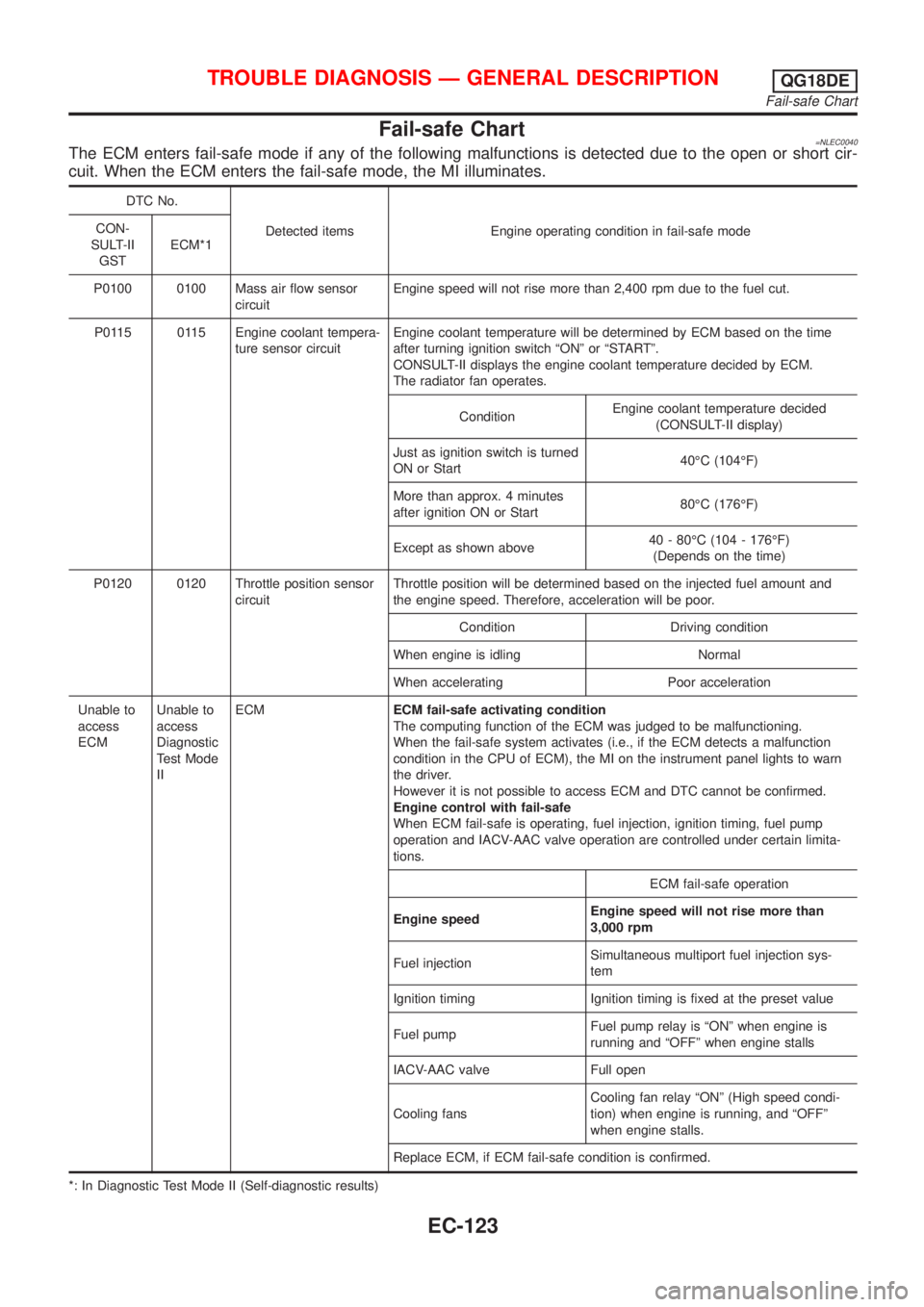
Fail-safe Chart=NLEC0040The ECM enters fail-safe mode if any of the following malfunctions is detected due to the open or short cir-
cuit. When the ECM enters the fail-safe mode, the MI illuminates.
DTC No.
Detected items Engine operating condition in fail-safe mode CON-
SULT-II
GSTECM*1
P0100 0100 Mass air flow sensor
circuitEngine speed will not rise more than 2,400 rpm due to the fuel cut.
P0115 0115 Engine coolant tempera-
ture sensor circuitEngine coolant temperature will be determined by ECM based on the time
after turning ignition switch ªONº or ªSTARTº.
CONSULT-II displays the engine coolant temperature decided by ECM.
The radiator fan operates.
ConditionEngine coolant temperature decided
(CONSULT-II display)
Just as ignition switch is turned
ON or Start40ÉC (104ÉF)
More than approx. 4 minutes
after ignition ON or Start80ÉC (176ÉF)
Except as shown above40 - 80ÉC (104 - 176ÉF)
(Depends on the time)
P0120 0120 Throttle position sensor
circuitThrottle position will be determined based on the injected fuel amount and
the engine speed. Therefore, acceleration will be poor.
Condition Driving condition
When engine is idling Normal
When accelerating Poor acceleration
Unable to
access
ECMUnable to
access
Diagnostic
Test Mode
IIECMECM fail-safe activating condition
The computing function of the ECM was judged to be malfunctioning.
When the fail-safe system activates (i.e., if the ECM detects a malfunction
condition in the CPU of ECM), the MI on the instrument panel lights to warn
the driver.
However it is not possible to access ECM and DTC cannot be confirmed.
Engine control with fail-safe
When ECM fail-safe is operating, fuel injection, ignition timing, fuel pump
operation and IACV-AAC valve operation are controlled under certain limita-
tions.
ECM fail-safe operation
Engine speedEngine speed will not rise more than
3,000 rpm
Fuel injectionSimultaneous multiport fuel injection sys-
tem
Ignition timing Ignition timing is fixed at the preset value
Fuel pumpFuel pump relay is ªONº when engine is
running and ªOFFº when engine stalls
IACV-AAC valve Full open
Cooling fansCooling fan relay ªONº (High speed condi-
tion) when engine is running, and ªOFFº
when engine stalls.
Replace ECM, if ECM fail-safe condition is confirmed.
*: In Diagnostic Test Mode II (Self-diagnostic results)
TROUBLE DIAGNOSIS Ð GENERAL DESCRIPTIONQG18DE
Fail-safe Chart
EC-123
Page 550 of 3051
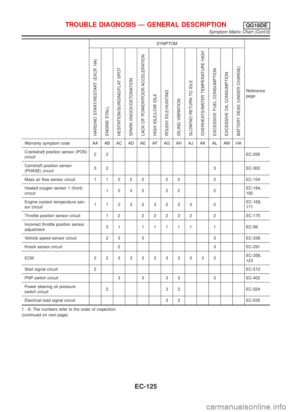
SYMPTOM
Reference
page
HARD/NO START/RESTART (EXCP. HA)
ENGINE STALL
HESITATION/SURGING/FLAT SPOT
SPARK KNOCK/DETONATION
LACK OF POWER/POOR ACCELERATION
HIGH IDLE/LOW IDLE
ROUGH IDLE/HUNTING
IDLING VIBRATION
SLOW/NO RETURN TO IDLE
OVERHEATS/WATER TEMPERATURE HIGH
EXCESSIVE FUEL CONSUMPTION
EXCESSIVE OIL CONSUMPTION
BATTERY DEAD (UNDER CHARGE)
Warranty symptom code AA AB AC AD AE AF AG AH AJ AK AL AM HA
Crankshaft position sensor (POS)
circuit22EC-295
Camshaft position sensor
(PHASE) circuit3 2 3 EC-302
Mass air flow sensor circuit11222 22 2EC-154
Heated oxygen sensor 1 (front)
circuit1232 22 2EC-184,
192
Engine coolant temperature sen-
sor circuit112323223 2EC-169,
171
Throttle position sensor circuit 1 222222 2EC-175
Incorrect throttle position sensor
adjustment31 11111 1EC-99
Vehicle speed sensor circuit 2 3 3 3 EC-338
Knock sensor circuit 2 3 EC-291
ECM 22333333333EC-358,
123
Start signal circuit 2EC-512
PNP switch circuit 3 3 3 3 3 EC-402
Power steering oil pressure
switch circuit2 3 3 EC-524
Electrical load signal circuit 3 3 EC-535
1 - 6: The numbers refer to the order of inspection.
(continued on next page)
TROUBLE DIAGNOSIS Ð GENERAL DESCRIPTIONQG18DE
Symptom Matrix Chart (Cont'd)
EC-125
Page 552 of 3051
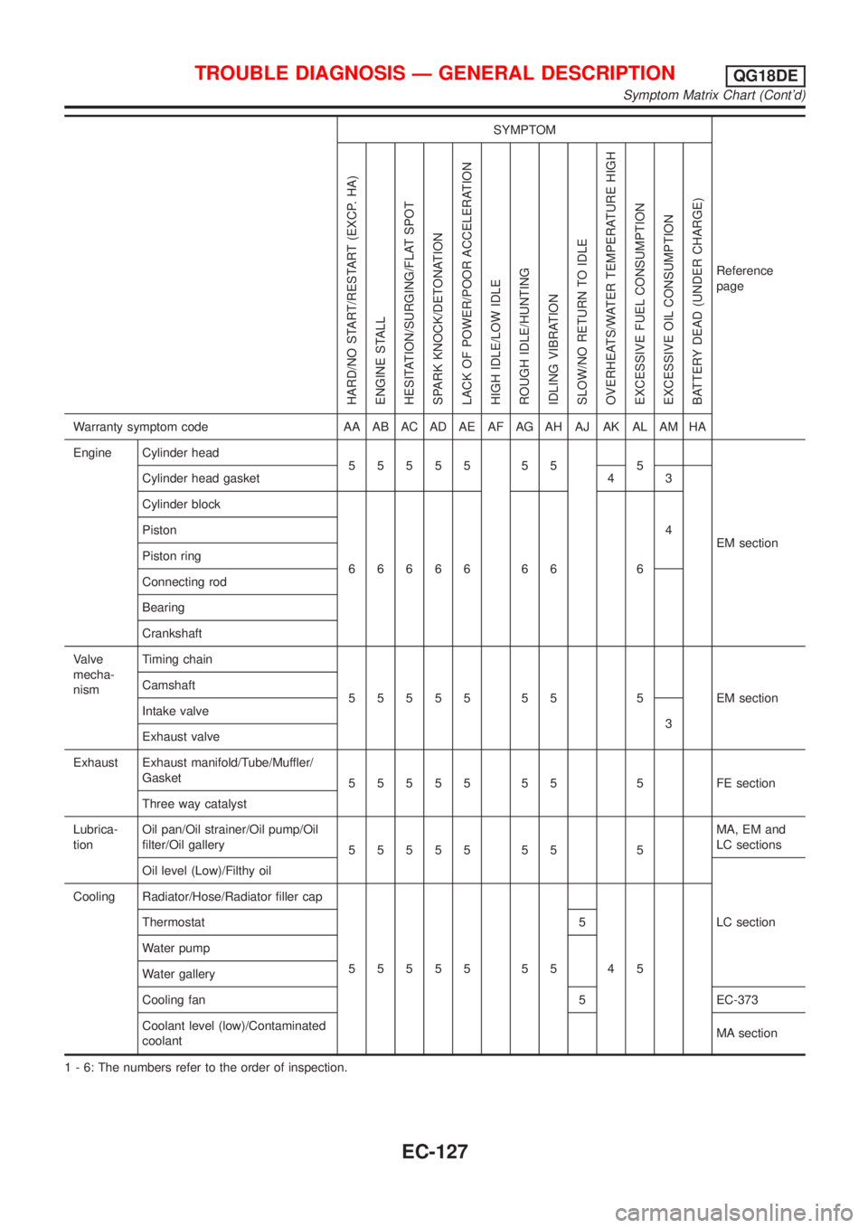
SYMPTOM
Reference
page
HARD/NO START/RESTART (EXCP. HA)
ENGINE STALL
HESITATION/SURGING/FLAT SPOT
SPARK KNOCK/DETONATION
LACK OF POWER/POOR ACCELERATION
HIGH IDLE/LOW IDLE
ROUGH IDLE/HUNTING
IDLING VIBRATION
SLOW/NO RETURN TO IDLE
OVERHEATS/WATER TEMPERATURE HIGH
EXCESSIVE FUEL CONSUMPTION
EXCESSIVE OIL CONSUMPTION
BATTERY DEAD (UNDER CHARGE)
Warranty symptom code AA AB AC AD AE AF AG AH AJ AK AL AM HA
Engine Cylinder head
55555 55 5
EM section Cylinder head gasket 4 3
Cylinder block
66666 66 64 Piston
Piston ring
Connecting rod
Bearing
Crankshaft
Valve
mecha-
nismTiming chain
55555 55 5 EMsection Camshaft
Intake valve
3
Exhaust valve
Exhaust Exhaust manifold/Tube/Muffler/
Gasket
55555 55 5 FEsection
Three way catalyst
Lubrica-
tionOil pan/Oil strainer/Oil pump/Oil
filter/Oil gallery
55555 55 5MA, EM and
LC sections
Oil level (Low)/Filthy oil
LC section Cooling Radiator/Hose/Radiator filler cap
55555 55 45 Thermostat 5
Water pump
Water gallery
Cooling fan 5 EC-373
Coolant level (low)/Contaminated
coolantMA section
1 - 6: The numbers refer to the order of inspection.
TROUBLE DIAGNOSIS Ð GENERAL DESCRIPTIONQG18DE
Symptom Matrix Chart (Cont'd)
EC-127
Page 554 of 3051
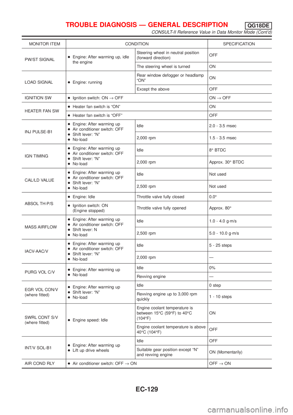
MONITOR ITEM CONDITION SPECIFICATION
PW/ST SIGNAL+Engine: After warming up, idle
the engineSteering wheel in neutral position
(forward direction)OFF
The steering wheel is turned ON
LOAD SIGNAL+Engine: runningRear window defogger or headlamp
ªONºON
Except the above OFF
IGNITION SW+Ignition switch: ON®OFF ON®OFF
HEATER FAN SW+Heater fan switch is ªONº ON
+Heater fan switch is ªOFFº OFF
INJ PULSE-B1+Engine: After warming up
+Air conditioner switch: OFF
+Shift lever: ªNº
+No-loadIdle 2.0 - 3.5 msec
2,000 rpm 1.5 - 3.5 msec
IGN TIMING+Engine: After warming up
+Air conditioner switch: OFF
+Shift lever: ªNº
+No-loadIdle 8É BTDC
2,000 rpm Approx. 30É BTDC
CAL/LD VALUE+Engine: After warming up
+Air conditioner switch: OFF
+Shift lever: ªNº
+No-loadIdle Not used
2,500 rpm Not used
ABSOL TH´P/S+Engine: Idle Throttle valve fully closed 0.0É
+Ignition switch: ON
(Engine stopped)Throttle valve fully opened Approx. 80É
MASS AIRFLOW+Engine: After warming up
+Air conditioner switch: OFF
+Shift lever: N
+No-loadIdle 1.0 - 4.0 g´m/s
2,500 rpm 5.0 - 10.0 g´m/s
IACV-AAC/V+Engine: After warming up
+Air conditioner switch: OFF
+Shift lever: ªNº
+No-loadIdle 5 - 25 steps
2,000 rpm Ð
PURG VOL C/V+Engine: After warming up
+No-loadIdle 0%
Revving engine Ð
EGR VOL CON/V
(where fitted)+Engine: After warming up
+Shift lever: ªNº
+No-loadIdle 0 step
Revving engine up to 3,000 rpm
quickly1 - 10 steps
SWRL CONT S/V
(where fitted)+Engine speed: IdleEngine coolant temperature is
between 15ÉC (59ÉF) to 40ÉC
(104ÉF)ON
Engine coolant temperature is above
40ÉC (104ÉF)OFF
INT/V SOL-B1+Engine: After warming up
+Lift up drive wheelsIdle OFF
Suitable gear position except ªNº
and revving engineON (Momentarily)
AIR COND RLY+Air conditioner switch: OFF®ON OFF®ON
TROUBLE DIAGNOSIS Ð GENERAL DESCRIPTIONQG18DE
CONSULT-II Reference Value in Data Monitor Mode (Cont'd)
EC-129
Page 555 of 3051
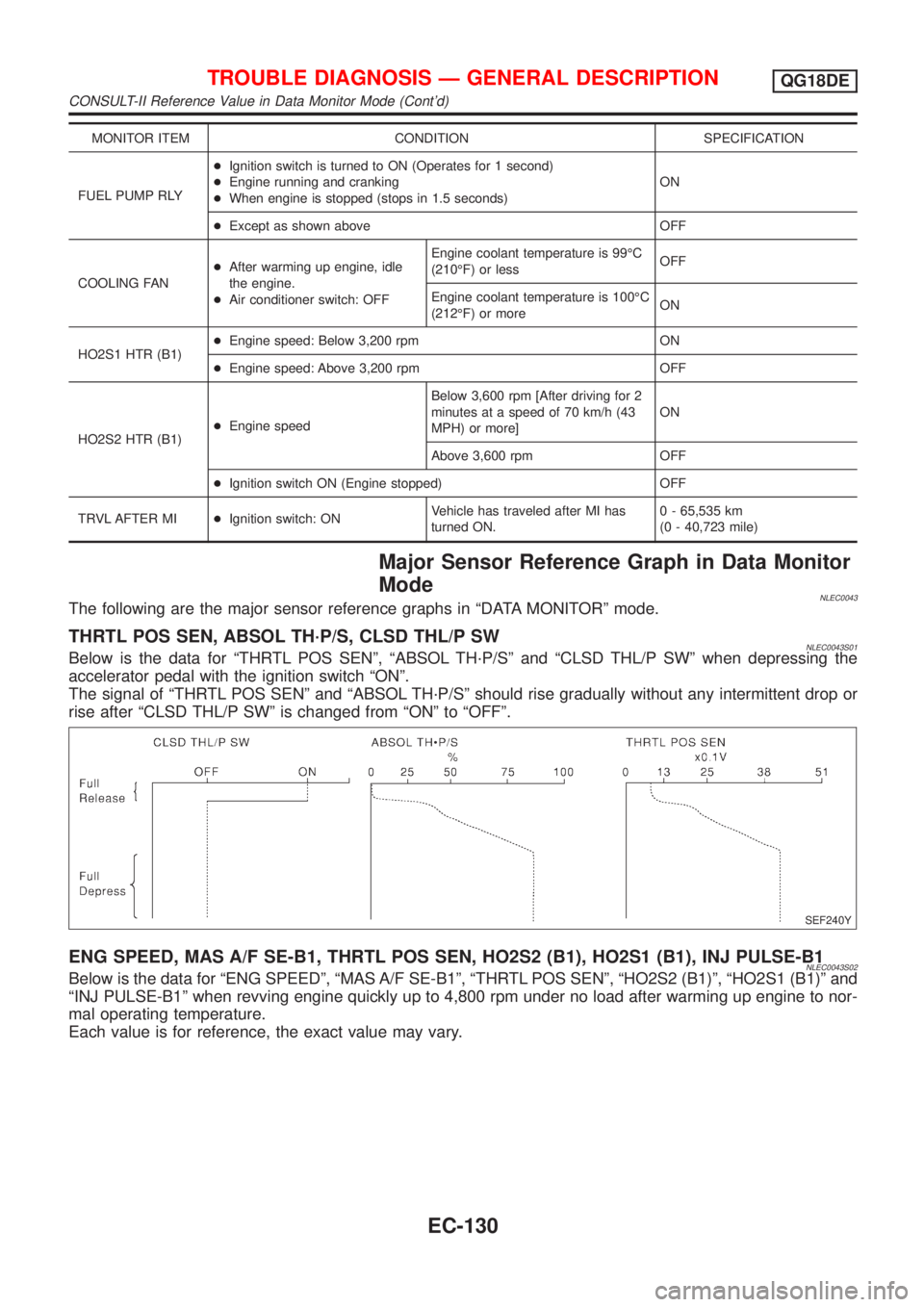
MONITOR ITEM CONDITION SPECIFICATION
FUEL PUMP RLY+Ignition switch is turned to ON (Operates for 1 second)
+Engine running and cranking
+When engine is stopped (stops in 1.5 seconds)ON
+Except as shown above OFF
COOLING FAN+After warming up engine, idle
the engine.
+Air conditioner switch: OFFEngine coolant temperature is 99ÉC
(210ÉF) or lessOFF
Engine coolant temperature is 100ÉC
(212ÉF) or moreON
HO2S1 HTR (B1)+Engine speed: Below 3,200 rpm ON
+Engine speed: Above 3,200 rpm OFF
HO2S2 HTR (B1)+Engine speedBelow 3,600 rpm [After driving for 2
minutes at a speed of 70 km/h (43
MPH) or more]ON
Above 3,600 rpm OFF
+Ignition switch ON (Engine stopped) OFF
TRVL AFTER MI+Ignition switch: ONVehicle has traveled after MI has
turned ON.0 - 65,535 km
(0 - 40,723 mile)
Major Sensor Reference Graph in Data Monitor
Mode
NLEC0043The following are the major sensor reference graphs in ªDATA MONITORº mode.
THRTL POS SEN, ABSOL TH´P/S, CLSD THL/P SWNLEC0043S01Below is the data for ªTHRTL POS SENº, ªABSOL TH´P/Sº and ªCLSD THL/P SWº when depressing the
accelerator pedal with the ignition switch ªONº.
The signal of ªTHRTL POS SENº and ªABSOL TH´P/Sº should rise gradually without any intermittent drop or
rise after ªCLSD THL/P SWº is changed from ªONº to ªOFFº.
SEF240Y
ENG SPEED, MAS A/F SE-B1, THRTL POS SEN, HO2S2 (B1), HO2S1 (B1), INJ PULSE-B1NLEC0043S02Below is the data for ªENG SPEEDº, ªMAS A/F SE-B1º, ªTHRTL POS SENº, ªHO2S2 (B1)º, ªHO2S1 (B1)º and
ªINJ PULSE-B1º when revving engine quickly up to 4,800 rpm under no load after warming up engine to nor-
mal operating temperature.
Each value is for reference, the exact value may vary.
TROUBLE DIAGNOSIS Ð GENERAL DESCRIPTIONQG18DE
CONSULT-II Reference Value in Data Monitor Mode (Cont'd)
EC-130
Page 563 of 3051
![NISSAN ALMERA TINO 2001 Service Repair Manual TERMI-
NAL
NO.WIRE
COLORITEM CONDITION DATA (DC Voltage)
51 LG/B Blower fan SW[Ignition switch ªONº]
+Blower fan switch is ªONºApproximately 0V
[Ignition switch ªONº]
+Blower fan switch is ªOFF](/manual-img/5/57352/w960_57352-562.png "NISSAN ALMERA TINO 2001 Service Repair Manual TERMI-
NAL
NO.WIRE
COLORITEM CONDITION DATA (DC Voltage)
51 LG/B Blower fan SW[Ignition switch ªONº]
+Blower fan switch is ªONºApproximately 0V
[Ignition switch ªONº]
+Blower fan switch is ªOFF")
TERMI-
NAL
NO.WIRE
COLORITEM CONDITION DATA (DC Voltage)
51 LG/B Blower fan SW[Ignition switch ªONº]
+Blower fan switch is ªONºApproximately 0V
[Ignition switch ªONº]
+Blower fan switch is ªOFFºApproximately 5V
57 B ECM ground[Engine is running]
+Idle speedEngine ground
58 B Sensors' ground[Engine is running]
+Warm-up condition
+Idle speedApproximately 0V
61 G Mass air flow sensor[Engine is running]
+Warm-up condition
+Idle speed1.0 - 1.7V
[Engine is running]
+Warm-up condition
+Engine speed is 2,500 rpm1.5 - 2.1V
62 WHeated oxygen sensor
1 (front)[Engine is running]
+Warm-up condition
+Engine speed is 2,000 rpm0 - Approximately 0.7V
SEF008W
63 LHeated oxygen sensor
2 (rear)[Engine is running]
+After warming up to normal operating tempera-
ture and engine speed is 3,000 rpm0 - Approximately 1.0V
64 Y/BIntake air temperature
sensor[Engine is running]Approximately 0 - 4.8V
Output voltage varies with
intake air temperature
66
75R
RCamshaft position sen-
sor (PHASE)[Engine is running]
+Warm-up condition
+Idle speed2.0 - 3.0V
SEF977W
[Engine is running]
+Engine speed is 2,000 rpm2.0 - 3.0V
SEF978W
67 W/LPower supply for ECM
(Back-up)[Ignition switch ªOFFº]BATTERY VOLTAGE
(11 - 14V)
70 BR/WEngine coolant tem-
perature sensor[Engine is running]Approximately 0 - 4.8V
Output voltage varies with
engine coolant temperature
TROUBLE DIAGNOSIS Ð GENERAL DESCRIPTIONQG18DE
ECM Terminals and Reference Value (Cont'd)
EC-138
Page 565 of 3051
![NISSAN ALMERA TINO 2001 Service Repair Manual TERMI-
NAL
NO.WIRE
COLORITEM CONDITION DATA (DC Voltage)
101
103
105
107R/B
YB
GB
L/BInjector No. 1
Injector No. 2
Injector No. 3
Injector No. 4[Engine is running]
+Warm-up condition
+Idle speedBATTER](/manual-img/5/57352/w960_57352-564.png "NISSAN ALMERA TINO 2001 Service Repair Manual TERMI-
NAL
NO.WIRE
COLORITEM CONDITION DATA (DC Voltage)
101
103
105
107R/B
YB
GB
L/BInjector No. 1
Injector No. 2
Injector No. 3
Injector No. 4[Engine is running]
+Warm-up condition
+Idle speedBATTER")
TERMI-
NAL
NO.WIRE
COLORITEM CONDITION DATA (DC Voltage)
101
103
105
107R/B
YB
GB
L/BInjector No. 1
Injector No. 2
Injector No. 3
Injector No. 4[Engine is running]
+Warm-up condition
+Idle speedBATTERY VOLTAGE
(11 - 14V)
SEF011W
[Engine is running]
+Warm-up condition
+Engine speed is 2,000 rpmBATTERY VOLTAGE
(11 - 14V)
SEF012W
104 SBSwirl control valve con-
trol solenoid valve
(where fitted)[Engine is running]
+Engine coolant temperature is between 15ÉC
(59ÉF) to 40ÉC (104ÉF)
+Idle speed0-1V
[Engine is running]
+Engine coolant temperature is above 40ÉC
(104ÉF)
+Idle speedBATTERY VOLTAGE
(11 - 14V)
106
108B/Y ECM ground[Engine is running]
+Idle speedEngine ground
11 0
11 2W
WPower supply for ECM[Ignition switch ªONº]BATTERY VOLTAGE
(11 - 14V)
111 R Sensors' power supply[Ignition switch ªONº]Approximately 5V
114 GY/R Adjust switch[Engine is running]
+Idle speed0V
115 LG Data link connector[Engine is running]
+Idle speed (CONSULT-II or GST is discon-
nected)0 - 10V
TROUBLE DIAGNOSIS Ð GENERAL DESCRIPTIONQG18DE
ECM Terminals and Reference Value (Cont'd)
EC-140