2001 NISSAN ALMERA TINO sensor
[x] Cancel search: sensorPage 33 of 3051
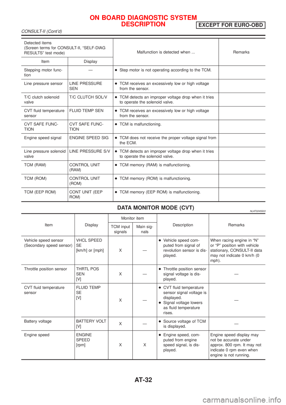
Detected items
(Screen terms for CONSULT-II, ªSELF-DIAG
RESULTSº test mode)Malfunction is detected when ... Remarks
Item Display
Stepping motor func-
tionÐ+Step motor is not operating according to the TCM.
Line pressure sensor LINE PRESSURE
SEN+TCM receives an excessively low or high voltage
from the sensor.
T/C clutch solenoid
valveT/C CLUTCH SOL/V+TCM detects an improper voltage drop when it tries
to operate the solenoid valve.
CVT fluid temperature
sensorFLUID TEMP SEN+TCM receives an excessively low or high voltage
from the sensor.
CVT SAFE FUNC-
TIONCVT SAFE FUNC-
TION+TCM is malfunctioning.
Engine speed signal ENGINE SPEED SIG+TCM does not receive the proper voltage signal from
the ECM.
Line pressure solenoid
valveLINE PRESSURE S/V+TCM detects an improper voltage drop when it tries
to operate the solenoid valve.
TCM (RAM) CONTROL UNIT
(RAM)+TCM memory (RAM) is malfunctioning.
TCM (ROM) CONTROL UNIT
(ROM)+TCM memory (ROM) is malfunctioning.
TCM (EEP ROM) CONT UNIT (EEP
ROM)+TCM memory (EEP ROM) is malfunctioning.
DATA MONITOR MODE (CVT)NLAT0245S03
Item DisplayMonitor item
Description Remarks
TCM input
signalsMain sig-
nals
Vehicle speed sensor
(Secondary speed sensor)VHCL SPEED
SE
[km/h] or [mph] X Ð+Vehicle speed com-
puted from signal of
revolution sensor is dis-
played.When racing engine in ªNº
or ªPº position with vehicle
stationary, CONSULT-II data
may not indicate 0 km/h (0
mph).
Throttle position sensor THRTL POS
SEN
[V]XÐ+Throttle position sensor
signal voltage is dis-
played.Ð
CVT fluid temperature
sensorFLUID TEMP
SE
[V]
XÐ+CVT fluid temperature
sensor signal voltage is
displayed.
+Signal voltage lowers
as fluid temperature
rises.Ð
Battery voltage BATTERY VOLT
[V]XÐ+Source voltage of TCM
is displayed.Ð
Engine speed ENGINE
SPEED
[rpm] X X+Engine speed, com-
puted from engine
speed signal, is dis-
played.Engine speed display may
not be accurate under
approx. 800 rpm. It may not
indicate 0 rpm even when
engine is not running.
ON BOARD DIAGNOSTIC SYSTEM
DESCRIPTION
EXCEPT FOR EURO-OBD
CONSULT-II (Cont'd)
AT-32
Page 35 of 3051
![NISSAN ALMERA TINO 2001 Service Repair Manual Item DisplayMonitor item
Description Remarks
TCM input
signalsMain sig-
nals
Line pressure sensor LINE PRES
SEN [V] X Ð+CVT fluid pressure sen-
sor signal voltage is
displayed.Ð
Primary pulley speed](/manual-img/5/57352/w960_57352-34.png "NISSAN ALMERA TINO 2001 Service Repair Manual Item DisplayMonitor item
Description Remarks
TCM input
signalsMain sig-
nals
Line pressure sensor LINE PRES
SEN [V] X Ð+CVT fluid pressure sen-
sor signal voltage is
displayed.Ð
Primary pulley speed")
Item DisplayMonitor item
Description Remarks
TCM input
signalsMain sig-
nals
Line pressure sensor LINE PRES
SEN [V] X Ð+CVT fluid pressure sen-
sor signal voltage is
displayed.Ð
Primary pulley speed sen-
sorI/P PULLY SPD
[rpm]
XX+Primary pulley speed
computed from signal
of primary pulley speed
sensor is displayed.
Secondary pulley speed
sensorO/P PULLY SPD
[rpm]
ÐÐ+Secondary pulley speed
computed from signal
of secondary speed
sensor is displayed.Ð
Stop lamp switch BRAKE SW
[ON/OFF] X Ð+ON/OFF position signal
of stop lamp switch is
displayed.Ð
ABS signal ABS SIGNAL
[ON/OFF]
XÐ+ABS operation signal
(ON/OFF) from ABS
control unit is dis-
played.Ð
CVT ratio CVT RATIO [Ð]
ÐX+Real CVT ratio oper-
ated TCM is displayed.Ð
Step PLY CONT
STEP [step]ÐX+Step motor position is
displayed.Ð
X: Applicable
Ð: Not applicable
SAT250K
HOW TO ERASE SELF-DIAGNOSTIC RESULTS
(
WITH CONSULT-II)NLAT0245S091. If the ignition switch stays ªONº after repair work, be sure to
turn ignition switch ªOFFº once. Wait for at least 3 seconds and
then turn it ªONº again.
2. Turn CONSULT-II ªONº, and touch ªCVTº.
SAT252K
3. Touch ªSELF-DIAG RESULTSº.
ON BOARD DIAGNOSTIC SYSTEM
DESCRIPTION
EXCEPT FOR EURO-OBD
CONSULT-II (Cont'd)
AT-34
Page 39 of 3051
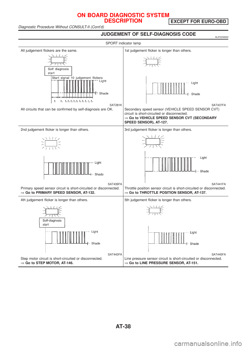
JUDGEMENT OF SELF-DIAGNOSIS CODENLAT0246S02
SPORT indicator lamp
All judgement flickers are the same.
SAT281K
All circuits that can be confirmed by self-diagnosis are OK.1st judgement flicker is longer than others.
SAT437FA
Secondary speed sensor (VEHICLE SPEED SENSOR CVT)
circuit is short-circuited or disconnected.
ÞGo to VEHICLE SPEED SENSOR CVT (SECONDARY
SPEED SENSOR), AT-127.
2nd judgement flicker is longer than others.
SAT439FA
Primary speed sensor circuit is short-circuited or disconnected.
ÞGo to PRIMARY SPEED SENSOR, AT-132.3rd judgement flicker is longer than others.
SAT441FA
Throttle position sensor circuit is short-circuited or disconnected.
ÞGo to THROTTLE POSITION SENSOR, AT-137.
4th judgement flicker is longer than others.
SAT443FA
Step motor circuit is short-circuited or disconnected.
ÞGo to STEP MOTOR, AT-146.5th judgement flicker is longer than others.
SAT445FA
Line pressure sensor circuit is short-circuited or disconnected.
ÞGo to LINE PRESSURE SENSOR, AT-151.
ON BOARD DIAGNOSTIC SYSTEM
DESCRIPTION
EXCEPT FOR EURO-OBD
Diagnostic Procedure Without CONSULT-II (Cont'd)
AT-38
Page 40 of 3051
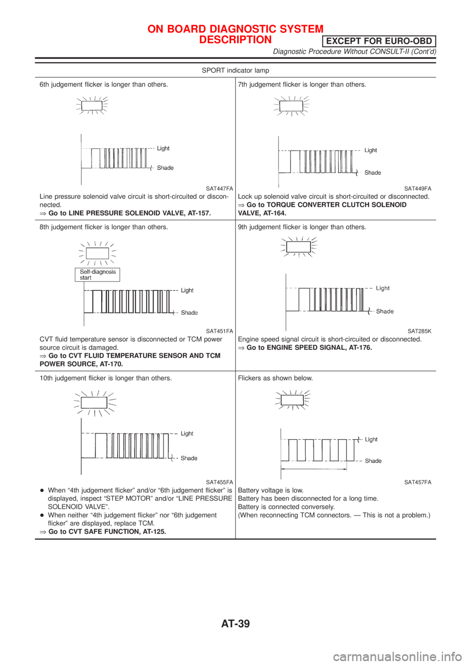
SPORT indicator lamp
6th judgement flicker is longer than others.
SAT447FA
Line pressure solenoid valve circuit is short-circuited or discon-
nected.
ÞGo to LINE PRESSURE SOLENOID VALVE, AT-157.7th judgement flicker is longer than others.
SAT449FA
Lock up solenoid valve circuit is short-circuited or disconnected.
ÞGo to TORQUE CONVERTER CLUTCH SOLENOID
VALVE, AT-164.
8th judgement flicker is longer than others.
SAT451FA
CVT fluid temperature sensor is disconnected or TCM power
source circuit is damaged.
ÞGo to CVT FLUID TEMPERATURE SENSOR AND TCM
POWER SOURCE, AT-170.9th judgement flicker is longer than others.
SAT285K
Engine speed signal circuit is short-circuited or disconnected.
ÞGo to ENGINE SPEED SIGNAL, AT-176.
10th judgement flicker is longer than others.
SAT455FA
+When ª4th judgement flickerº and/or ª6th judgement flickerº is
displayed, inspect ªSTEP MOTORº and/or ªLINE PRESSURE
SOLENOID VALVEº.
+When neither ª4th judgement flickerº nor ª6th judgement
flickerº are displayed, replace TCM.
ÞGo to CVT SAFE FUNCTION, AT-125.Flickers as shown below.
SAT457FA
Battery voltage is low.
Battery has been disconnected for a long time.
Battery is connected conversely.
(When reconnecting TCM connectors. Ð This is not a problem.)
ON BOARD DIAGNOSTIC SYSTEM
DESCRIPTION
EXCEPT FOR EURO-OBD
Diagnostic Procedure Without CONSULT-II (Cont'd)
AT-39
Page 42 of 3051

SAT631IA
SAT632I
SEF234G
IntroductionNLAT0023The TCM receives a signal from the vehicle speed sensor, throttle
position sensor or PNP switch and provides shift control or lock-up
control via step motor and CVT solenoid valves.
The TCM also communicates with the ECM by means of a signal
sent from sensing elements used with the EURO-OBD-related
parts of the CVT system for malfunction-diagnostic purposes. The
TCM is capable of diagnosing malfunctioning parts while the ECM
can store malfunctions in its memory.
Input and output signals must always be correct and stable in the
operation of the CVT system. The CVT system must be in good
operating condition and be free of valve seizure, solenoid valve
malfunction, etc.
It is much more difficult to diagnose a problem that occurs intermit-
tently rather than continuously. Most intermittent problems are
caused by poor electric connections or improper wiring. In this
case, careful checking of suspected circuits may help prevent the
replacement of good parts.
A visual check only, may not find the cause of the problems. A road
test with CONSULT-II (or GST) or a circuit tester connected should
be performed. Follow the ªWork Flowº. Refer to AT-44.
Before undertaking actual checks, take a few minutes to talk with
a customer who approaches with a driveability complaint. The cus-
tomer can supply good information about such problems, espe-
cially intermittent ones. Find out what symptoms are present and
under what conditions they occur. A ªDiagnostic Worksheetº like the
example (AT-43) should be used.
Start your diagnosis by looking for ªconventionalº problems first.
This will help troubleshoot driveability problems on an electronically
controlled engine vehicle.
Also check related Service bulletins for information.
TROUBLE DIAGNOSIS Ð INTRODUCTIONEURO-OBD
AT-41
Page 44 of 3051
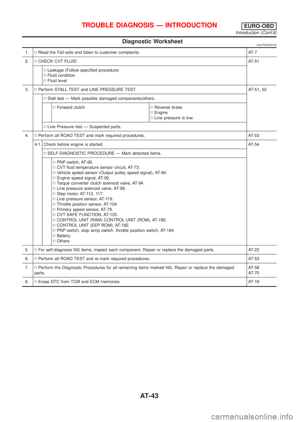
Diagnostic Worksheet=NLAT0023S0102
1.NRead the Fail-safe and listen to customer complaints. AT-7
2.NCHECK CVT FLUIDAT-51
NLeakage (Follow specified procedure)
NFluid condition
NFluid level
3.NPerform STALL TEST and LINE PRESSURE TEST. AT-51, 52
NStall test Ð Mark possible damaged components/others.
NForward clutchNReverse brake
NEngine
NLine pressure is low.
NLine Pressure test Ð Suspected parts:
4.NPerform all ROAD TEST and mark required procedures. AT-53
4-1. Check before engine is started.AT-54
NSELF-DIAGNOSTIC PROCEDURE Ð Mark detected items.
NPNP switch, AT-66.
NCVT fluid temperature sensor circuit, AT-73.
NVehicle speed sensor (Output pulley speed signal), AT-84.
NEngine speed signal, AT-90.
NTorque converter clutch solenoid valve, AT-94.
NLine pressure solenoid valve, AT-99.
NStep motor, AT-112, 117.
NLine pressure sensor, AT-119.
NThrottle position sensor, AT-104.
NPrimary speed sensor, AT-79.
NCVT SAFE FUNCTION, AT-125.
NCONTROL UNIT (RAM) CONTROL UNIT (ROM), AT-180.
NCONTROL UNIT (EEP ROM), AT-182.
NPNP switch, stop lamp switch, throttle position switch, AT-184.
NBattery
NOthers
5.NFor self-diagnosis NG items, inspect each component. Repair or replace the damaged parts. AT-22
6.NPerform all ROAD TEST and re-mark required procedures. AT-53
7.NPerform the Diagnostic Procedures for all remaining items marked NG. Repair or replace the damaged
parts.AT-58
AT-70
8.NErase DTC from TCM and ECM memories. AT-19
TROUBLE DIAGNOSIS Ð INTRODUCTIONEURO-OBD
Introduction (Cont'd)
AT-43
Page 47 of 3051
SAT631IA
SAT632I
SEF234G
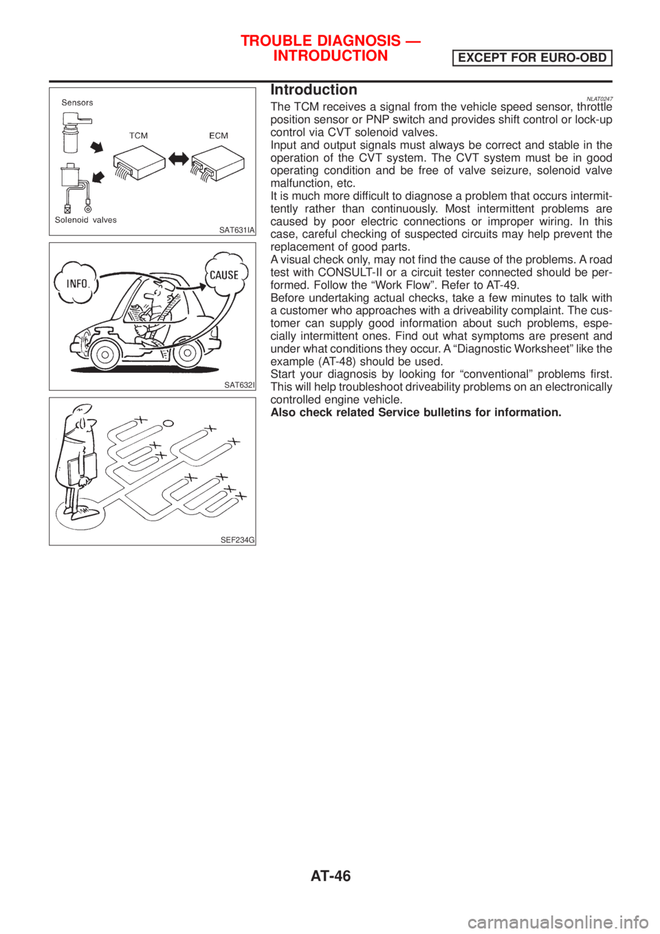
IntroductionNLAT0247The TCM receives a signal from the vehicle speed sensor, throttle
position sensor or PNP switch and provides shift control or lock-up
control via CVT solenoid valves.
Input and output signals must always be correct and stable in the
operation of the CVT system. The CVT system must be in good
operating condition and be free of valve seizure, solenoid valve
malfunction, etc.
It is much more difficult to diagnose a problem that occurs intermit-
tently rather than continuously. Most intermittent problems are
caused by poor electric connections or improper wiring. In this
case, careful checking of suspected circuits may help prevent the
replacement of good parts.
A visual check only, may not find the cause of the problems. A road
test with CONSULT-II or a circuit tester connected should be per-
formed. Follow the ªWork Flowº. Refer to AT-49.
Before undertaking actual checks, take a few minutes to talk with
a customer who approaches with a driveability complaint. The cus-
tomer can supply good information about such problems, espe-
cially intermittent ones. Find out what symptoms are present and
under what conditions they occur. A ªDiagnostic Worksheetº like the
example (AT-48) should be used.
Start your diagnosis by looking for ªconventionalº problems first.
This will help troubleshoot driveability problems on an electronically
controlled engine vehicle.
Also check related Service bulletins for information.
TROUBLE DIAGNOSIS Ð
INTRODUCTION
EXCEPT FOR EURO-OBD
AT-46
Page 49 of 3051
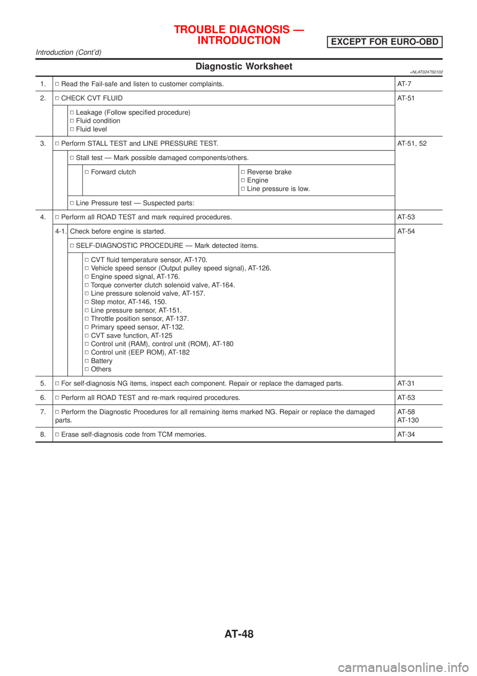
Diagnostic Worksheet=NLAT0247S0102
1.NRead the Fail-safe and listen to customer complaints. AT-7
2.NCHECK CVT FLUIDAT-51
NLeakage (Follow specified procedure)
NFluid condition
NFluid level
3.NPerform STALL TEST and LINE PRESSURE TEST. AT-51, 52
NStall test Ð Mark possible damaged components/others.
NForward clutchNReverse brake
NEngine
NLine pressure is low.
NLine Pressure test Ð Suspected parts:
4.NPerform all ROAD TEST and mark required procedures. AT-53
4-1. Check before engine is started.AT-54
NSELF-DIAGNOSTIC PROCEDURE Ð Mark detected items.
NCVT fluid temperature sensor, AT-170.
NVehicle speed sensor (Output pulley speed signal), AT-126.
NEngine speed signal, AT-176.
NTorque converter clutch solenoid valve, AT-164.
NLine pressure solenoid valve, AT-157.
NStep motor, AT-146, 150.
NLine pressure sensor, AT-151.
NThrottle position sensor, AT-137.
NPrimary speed sensor, AT-132.
NCVT save function, AT-125
NControl unit (RAM), control unit (ROM), AT-180
NControl unit (EEP ROM), AT-182
NBattery
NOthers
5.NFor self-diagnosis NG items, inspect each component. Repair or replace the damaged parts. AT-31
6.NPerform all ROAD TEST and re-mark required procedures. AT-53
7.NPerform the Diagnostic Procedures for all remaining items marked NG. Repair or replace the damaged
parts.AT-58
AT-130
8.NErase self-diagnosis code from TCM memories. AT-34
TROUBLE DIAGNOSIS Ð
INTRODUCTION
EXCEPT FOR EURO-OBD
Introduction (Cont'd)
AT-48