Page 187 of 3051
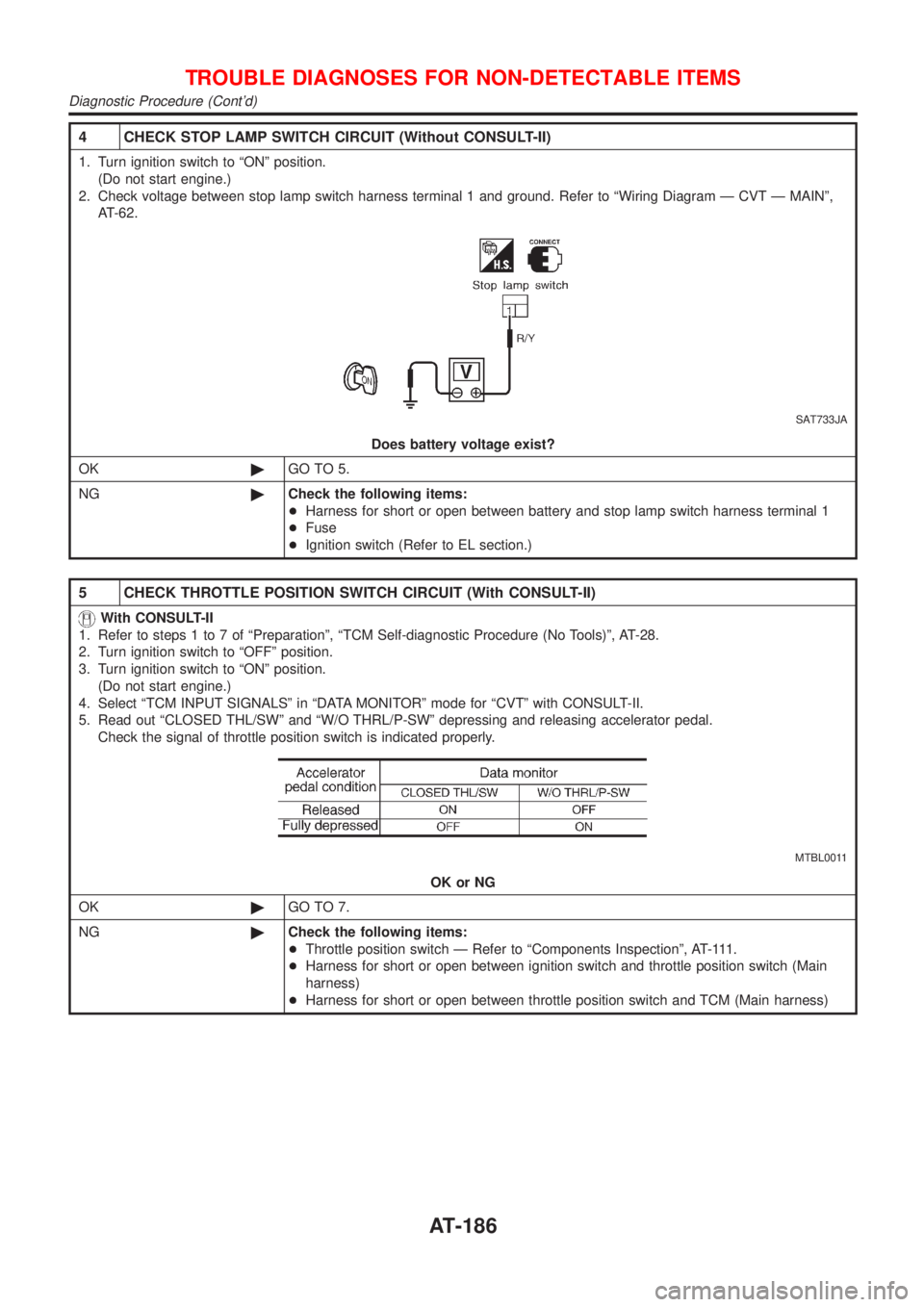
4 CHECK STOP LAMP SWITCH CIRCUIT (Without CONSULT-II)
1. Turn ignition switch to ªONº position.
(Do not start engine.)
2. Check voltage between stop lamp switch harness terminal 1 and ground. Refer to ªWiring Diagram Ð CVT Ð MAINº,
AT-62.
SAT733JA
Does battery voltage exist?
OK©GO TO 5.
NG©Check the following items:
+Harness for short or open between battery and stop lamp switch harness terminal 1
+Fuse
+Ignition switch (Refer to EL section.)
5 CHECK THROTTLE POSITION SWITCH CIRCUIT (With CONSULT-II)
With CONSULT-II
1. Refer to steps 1 to 7 of ªPreparationº, ªTCM Self-diagnostic Procedure (No Tools)º, AT-28.
2. Turn ignition switch to ªOFFº position.
3. Turn ignition switch to ªONº position.
(Do not start engine.)
4. Select ªTCM INPUT SIGNALSº in ªDATA MONITORº mode for ªCVTº with CONSULT-II.
5. Read out ªCLOSED THL/SWº and ªW/O THRL/P-SWº depressing and releasing accelerator pedal.
Check the signal of throttle position switch is indicated properly.
MTBL0011
OK or NG
OK©GO TO 7.
NG©Check the following items:
+Throttle position switch Ð Refer to ªComponents Inspectionº, AT-111.
+Harness for short or open between ignition switch and throttle position switch (Main
harness)
+Harness for short or open between throttle position switch and TCM (Main harness)
TROUBLE DIAGNOSES FOR NON-DETECTABLE ITEMS
Diagnostic Procedure (Cont'd)
AT-186
Page 188 of 3051
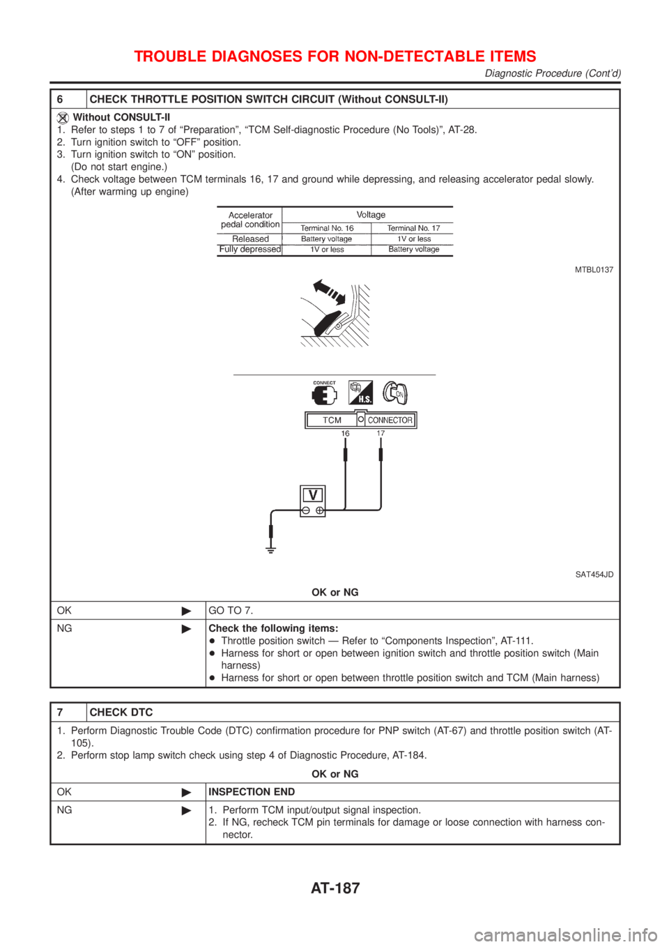
6 CHECK THROTTLE POSITION SWITCH CIRCUIT (Without CONSULT-II)
Without CONSULT-II
1. Refer to steps 1 to 7 of ªPreparationº, ªTCM Self-diagnostic Procedure (No Tools)º, AT-28.
2. Turn ignition switch to ªOFFº position.
3. Turn ignition switch to ªONº position.
(Do not start engine.)
4. Check voltage between TCM terminals 16, 17 and ground while depressing, and releasing accelerator pedal slowly.
(After warming up engine)
MTBL0137
SAT454JD
OK or NG
OK©GO TO 7.
NG©Check the following items:
+Throttle position switch Ð Refer to ªComponents Inspectionº, AT-111.
+Harness for short or open between ignition switch and throttle position switch (Main
harness)
+Harness for short or open between throttle position switch and TCM (Main harness)
7 CHECK DTC
1. Perform Diagnostic Trouble Code (DTC) confirmation procedure for PNP switch (AT-67) and throttle position switch (AT-
105).
2. Perform stop lamp switch check using step 4 of Diagnostic Procedure, AT-184.
OK or NG
OK©INSPECTION END
NG©1. Perform TCM input/output signal inspection.
2. If NG, recheck TCM pin terminals for damage or loose connection with harness con-
nector.
TROUBLE DIAGNOSES FOR NON-DETECTABLE ITEMS
Diagnostic Procedure (Cont'd)
AT-187
Page 199 of 3051
Diagnostic ProcedureNLAT0319SYMPTOM 1:
+Selector lever cannot be moved from ªPº position with key
in ON position and brake pedal applied.
+Selector lever can be moved from ªPº position with key in
ON position and brake pedal released.
+Selector lever can be moved from ªPº position when key
is removed from key cylinder.
SYMPTOM 2:
Ignition key cannot be removed when selector lever is set to
ªPº position. It can be removed when selector lever is set to
any position except ªPº.
1 CHECK KEY INTERLOCK CABLE
Check key interlock cable for damage.
OK or NG
OK©GO TO 2.
NG©Repair key interlock cable. Refer to AT-202.
2 CHECK SELECTOR LEVER POSITION
Check selector lever position for damage.
OK or NG
OK©GO TO 3.
NG©Check selector lever. Refer to ªON-VEHICLE SERVICE Ð PNP Switch and Control
Cable Adjustmentº, AT-204.
3 CHECK POWER SOURCE
1. Turn ignition switch to ªONº position.
(Do not start engine.)
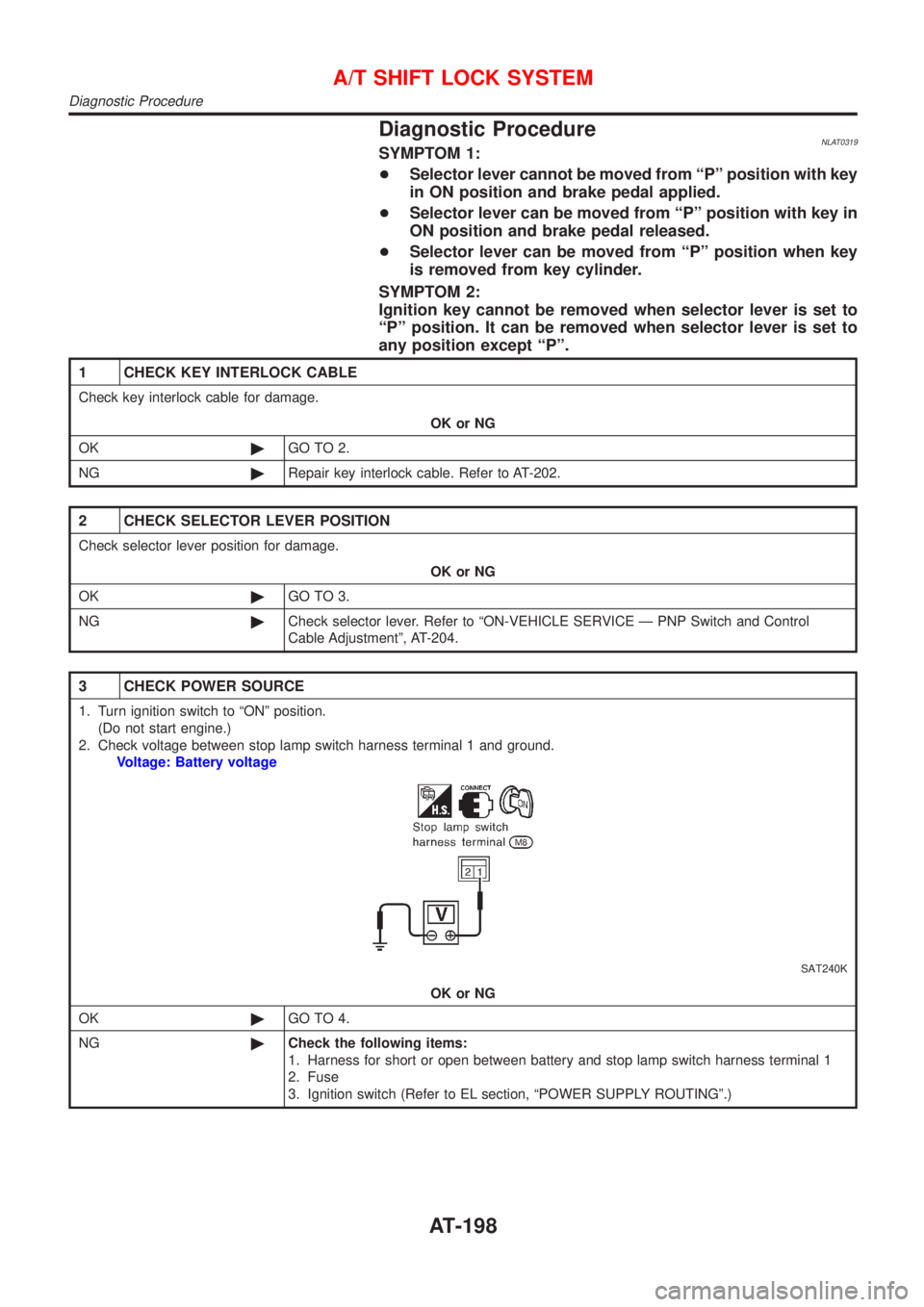
2. Check voltage between stop lamp switch harness terminal 1 and ground.
Voltage: Battery voltage
SAT240K
OK or NG
OK©GO TO 4.
NG©Check the following items:
1. Harness for short or open between battery and stop lamp switch harness terminal 1
2. Fuse
3. Ignition switch (Refer to EL section, ªPOWER SUPPLY ROUTINGº.)
A/T SHIFT LOCK SYSTEM
Diagnostic Procedure
AT-198
Page 200 of 3051
4 CHECK INPUT SIGNAL (A/T DEVICE)
Turn ignition switch to ªONº position.
(Do not start engine.)
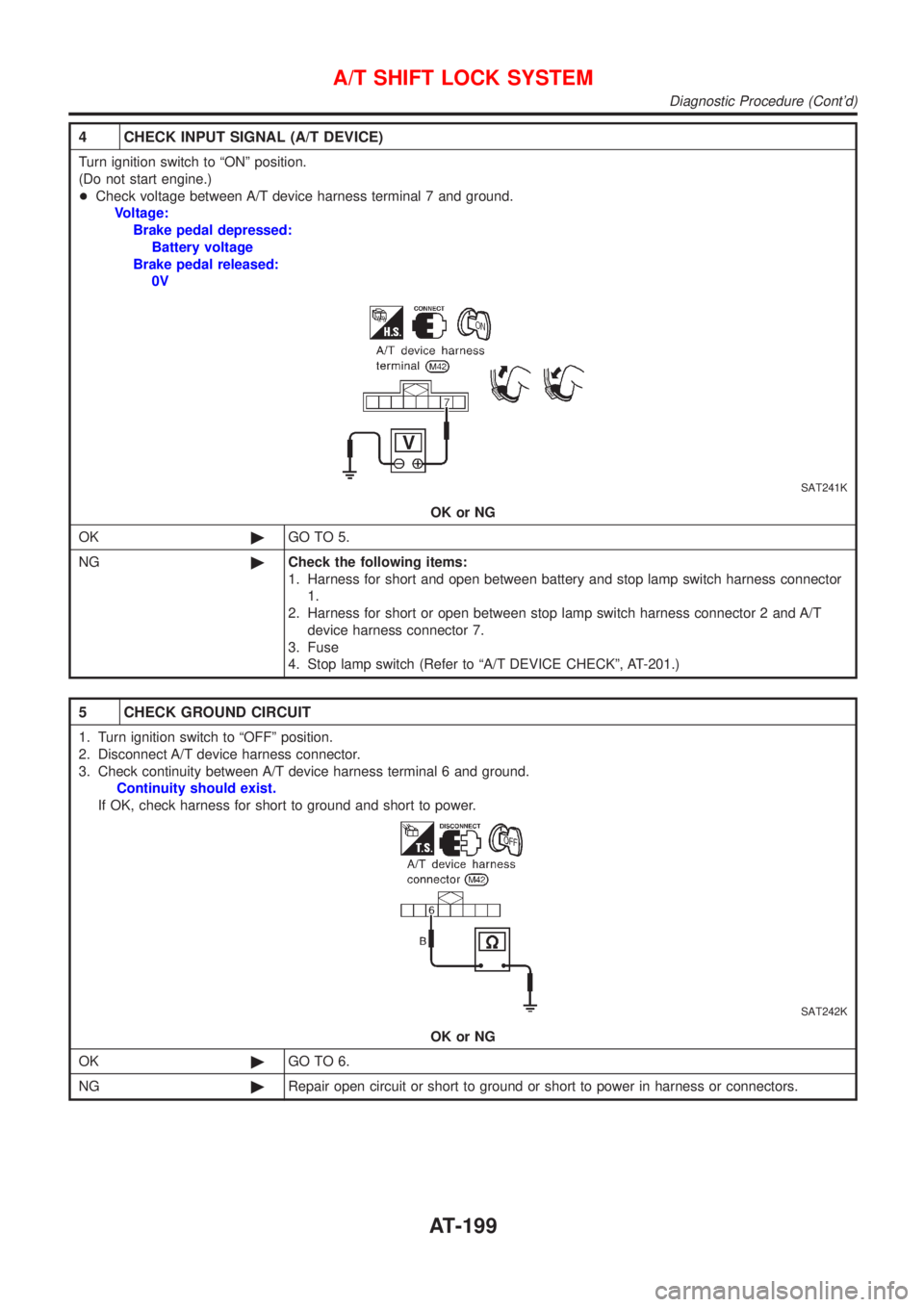
+Check voltage between A/T device harness terminal 7 and ground.
Voltage:
Brake pedal depressed:
Battery voltage
Brake pedal released:
0V
SAT241K
OK or NG
OK©GO TO 5.
NG©Check the following items:
1. Harness for short and open between battery and stop lamp switch harness connector
1.
2. Harness for short or open between stop lamp switch harness connector 2 and A/T
device harness connector 7.
3. Fuse
4. Stop lamp switch (Refer to ªA/T DEVICE CHECKº, AT-201.)
5 CHECK GROUND CIRCUIT
1. Turn ignition switch to ªOFFº position.
2. Disconnect A/T device harness connector.
3. Check continuity between A/T device harness terminal 6 and ground.
Continuity should exist.
If OK, check harness for short to ground and short to power.
SAT242K
OK or NG
OK©GO TO 6.
NG©Repair open circuit or short to ground or short to power in harness or connectors.
A/T SHIFT LOCK SYSTEM
Diagnostic Procedure (Cont'd)
AT-199
Page 253 of 3051
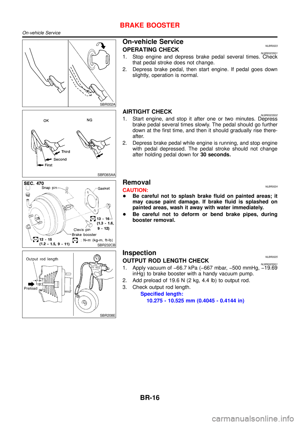
SBR002A
On-vehicle ServiceNLBR0023OPERATING CHECKNLBR0023S011. Stop engine and depress brake pedal several times. Check
that pedal stroke does not change.
2. Depress brake pedal, then start engine. If pedal goes down
slightly, operation is normal.
SBR365AA
AIRTIGHT CHECKNLBR0023S021. Start engine, and stop it after one or two minutes. Depress
brake pedal several times slowly. The pedal should go further
down at the first time, and then it should gradually rise there-
after.
2. Depress brake pedal while engine is running, and stop engine
with pedal depressed. The pedal stroke should not change
after holding pedal down for30 seconds.
SBR232CB
RemovalNLBR0024CAUTION:
+Be careful not to splash brake fluid on painted areas; it
may cause paint damage. If brake fluid is splashed on
painted areas, wash it away with water immediately.
+Be careful not to deform or bend brake pipes, during
booster removal.
SBR208E
InspectionNLBR0025OUTPUT ROD LENGTH CHECKNLBR0025S011. Apply vacuum of �66.7 kPa (�667 mbar, �500 mmHg, �19.69
inHg) to brake booster with a handy vacuum pump.
2. Add preload of 19.6 N (2 kg, 4.4 lb) to output rod.
3. Check output rod length.
Specified length:
10.275 - 10.525 mm (0.4045 - 0.4144 in)
BRAKE BOOSTER
On-vehicle Service
BR-16
Page 295 of 3051

CONSULT-IINLBR0092CONSULT-II APPLICATION TO ABSNLBR0092S01
ITEMSELF-DIAGNOSTIC
RESULTSDATA MONITOR ACTIVE TEST
Front right wheel sensor X X—
Front left wheel sensor X X—
Rear right wheel sensor X X—
Rear left wheel sensor X X—
Stop lamp switch—X—
Front right inlet solenoid valve X X X
Front right outlet solenoid valve X X X
Front left inlet solenoid valve X X X
Front left outlet solenoid valve X X X
Rear right inlet solenoid valve X X X
Rear right outlet solenoid valve X X X
Rear left inlet solenoid valve X X X
Rear left outlet solenoid valve X X X
Actuator solenoid valve relay X X—
Actuator motor relay
(ABS MOTOR is shown on the ACTIVE TEST
screen.)XXX
ABS warning lamp—X—
Battery voltage X X—
Control unit X——
X: Applicable
—: Not applicable
ECU (ABS CONTROL UNIT) PART NUMBER MODENLBR0092S02Ignore the ECU part number displayed in the ECU PART NUMBER MODE. Refer to parts catalog to order
the ABS actuator and electric unit.
NBR371
CONSULT-II Inspection ProcedureNLBR0093SELF-DIAGNOSIS PROCEDURENLBR0093S011. Turn ignition switch OFF.
2. Connect CONSULT-II to data link connector.
3. Start engine.
4. Drive vehicle over 30 km/h (19 MPH) for at least one minute.
ON BOARD DIAGNOSTIC SYSTEM DESCRIPTIONABS
CONSULT-II
BR-58
Page 296 of 3051
PBR455D
5. Stop vehicle with engine running and touch“START”on CON-
SULT-II screen.
C2SSE01
6. Touch“ABS”.
C2SDM01
7. Touch“SELF-DIAG RESULTS”.
+The screen shows the detected malfunction and how many
times the ignition switch has been turned since the malfunc-
tion.
8. Make the necessary repairs following the diagnostic proce-
dures.
SBR561E
9. After the malfunctions are repaired, erase the self-diagnostic
results stored in the control unit by touching“ERASE”.
10. Check ABS warning lamp for deactivation after driving vehicle
over 30 km/h (19 MPH) for at least one minute.
NOTE:
“SELF-DIAG RESULTS”screen shows the detected malfunction
and how many times the ignition switch has been turned since the
malfunction.
ON BOARD DIAGNOSTIC SYSTEM DESCRIPTIONABS
CONSULT-II Inspection Procedure (Cont’d)
BR-59
Page 300 of 3051

DATA MONITOR MODENLBR0093S05
MONITOR ITEM CONDITION SPECIFICATION
FR RH SENSOR
FR LH SENSOR
RR RH SENSOR
RR LH SENSORDrive vehicle.
(Each wheel is rotating.)Displays computed vehicle speed from wheel sensor signal.
Almost the same speed as speedometer.
STOP LAMP SWTurn ignition switch ON and
depress brake pedal.Depress the pedal: ON
Release the pedal: OFF
FR RH IN SOL
FR RH OUT SOL
FR LH IN SOL
FR LH OUT SOL
RR IN SOL
RR OUT SOL
RL IN SOL
RL OUT SOLIgnition switch is turned ON or
engine is running.Operating conditions for each solenoid valve are indicated.
ABS is not operating: OFF
ACTUATOR RELAY
Ignition switch is turned ON or
engine is running.Displays ON/OFF condition of ABS actuator relay.
When turning ignition switch ON, ABS actuator relay is oper-
ated.
MOTOR RELAYABS is not operating: OFF
ABS is operating: ON
WARNING LAMPWarning lamp is turned on: ON
Warning lamp is turned off: OFF
BATTERY VOLT Power supply voltage for control unit
ACTIVE TEST MODENLBR0093S06
TEST ITEM CONDITION JUDGEMENT
FR RH SOLENOID
FR LH SOLENOID
RR RH SOLENOID
RR LH SOLENOID
Ignition switch is turned ON.Brake fluid pressure control operation
IN SOL OUT SOL
UP (Increase): OFF OFF
KEEP (Hold): ON OFF
DOWN (Decrease): ON ON
ABS MOTORABS actuator motor
ON: Motor runs
OFF: Motor stops
NOTE:
Active test will automatically stop ten seconds after the test starts. (TEST IS STOPPED monitor shows ON.)
ON BOARD DIAGNOSTIC SYSTEM DESCRIPTIONABS
CONSULT-II Inspection Procedure (Cont’d)
BR-63