2001 NISSAN ALMERA TINO bulb
[x] Cancel search: bulbPage 1525 of 3051
DiagnosticTes tMod eIÐ BulbCheck
MI Condition
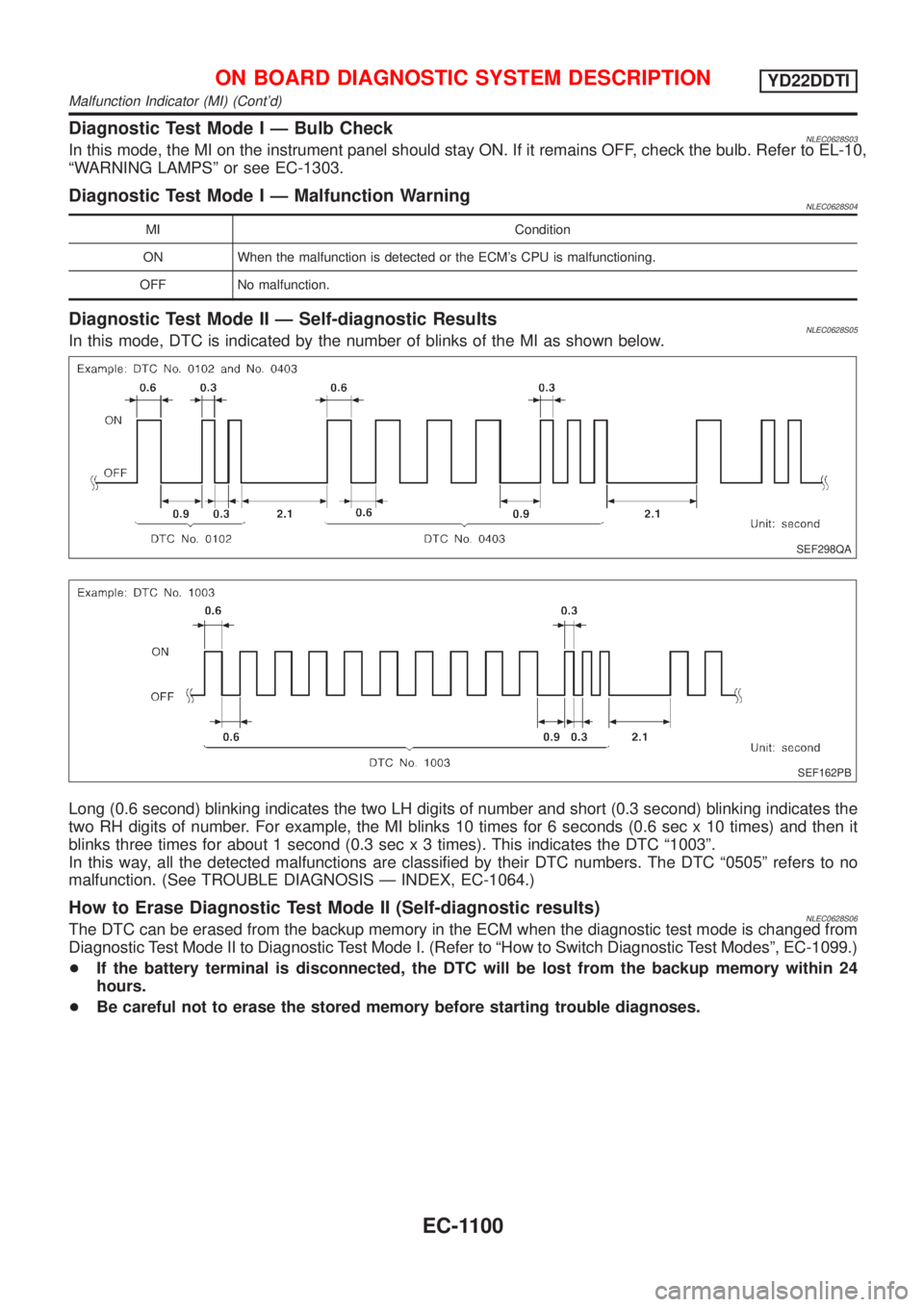
SEF298QA
SEF162PB
Malfunction Indicator (MI) (Cont'd)
Page 1732 of 3051
ELECTRICAL SYSTEM
SECTION
EL
CONTENTS
PRECAUTIONS...............................................................4
Supplemental Restraint System (SRS)²AIR
BAG²and²SEAT BELT PRE-TENSIONER²...............4
Wiring Diagrams and Trouble Diagnosis .....................4
HARNESS CONNECTOR................................................5
Description ...................................................................5
STANDARDIZED RELAY................................................7
Description ...................................................................7
POWER SUPPLY ROUTING...........................................9
Schematic ..................................................................10
Wiring Diagram - POWER - (Models with fuse
and fusible link box E43) ...........................................14
Wiring Diagram - POWER - (Models with fuse
and fusible link box E90) ...........................................24
Inspection...................................................................32
GROUND........................................................................33
Ground Distribution (Models with fuse and fusible
link box E43) ..............................................................33
Ground Distribution (Models with fuse and fusible
link box E90) ..............................................................48
COMBINATION SWITCH..............................................64
Check .........................................................................64
Replacement ..............................................................66
STEERING SWITCH......................................................67
Check .........................................................................67
HEADLAMP...................................................................69
Wiring Diagram - H/LAMP -.......................................69
Trouble Diagnoses.....................................................71
Bulb Replacement .....................................................71
Aiming Adjustment .....................................................72
HEADLAMP - DAYTIME LIGHT SYSTEM -.................73
System Description ....................................................73
Schematic ..................................................................74
Wiring Diagram - DTRL - ...........................................75
Trouble Diagnoses.....................................................81
Bulb Replacement .....................................................81
Aiming Adjustment .....................................................82
HEADLAMP - HEADLAMP AIMING CONTROL -........83
Wiring Diagram - H/AIM - ..........................................83PARKING, LICENSE AND TAIL LAMPS.....................87
Wiring Diagram - TAIL/L - ..........................................87
STOP LAMP..................................................................91
Wiring Diagram - STOP/L - .......................................91
BACK-UP LAMP............................................................93
Wiring Diagram - BACK/L - .......................................93
FRONT FOG LAMP.......................................................95
Wiring Diagram - F/FOG - .........................................95
Bulb Replacement .....................................................97
Aiming Adjustment .....................................................98
REAR FOG LAMP.........................................................99
Wiring Diagram - R/FOG -.........................................99
TURN SIGNAL AND HAZARD WARNING LAMPS...101
System Description ..................................................101
Wiring Diagram - TURN - ........................................102
Trouble Diagnoses...................................................106
ILLUMINATION............................................................107
Schematic ................................................................107
Wiring Diagram - ILL - .............................................109
INTERIOR ROOM LAMP............................................. 116
System Description .................................................. 116
Wiring Diagram - ROOM/L - .................................... 118
Trouble Diagnoses...................................................122
VANITY MIRROR AND LUGGAGE ROOM LAMPS..129
Wiring Diagram - INT/L - .........................................129
METERS AND GAUGES.............................................130
Component Parts and Harness Connector
Location ...................................................................130
System Description ..................................................130
Combination Meter ..................................................132
Schematic ................................................................134
Construction .............................................................136
Wiring Diagram - METER - .....................................137
Combination Meter Self-Diagnosis ..........................141
Trouble Diagnoses...................................................144
Electrical Components Inspection ...........................153
WARNING LAMPS......................................................155
Schematic ................................................................155
Wiring Diagram - WARN - .......................................156
Page 1734 of 3051
Passenger Compartment/LHD Models ....................444
Passenger Compartment/RHD Models ...................448
HARNESS LAYOUT....................................................452
How to Read Harness Layout .................................452
Outline......................................................................453
Main Harness...........................................................456
Instrument Harness and Audio Harness .................464
Engine Room Harness ............................................468
Engine Control Harness/QG Engine Models...........480
Engine Control Harness/SR Engine Models ...........488
Engine Control Harness/YD Engine Models ...........496Body Harness ..........................................................504
Room Lamp Harness...............................................512
Front Door Harness/LHD Models ............................513
Front Door Harness/RHD Models ...........................517
Rear Door Harness..................................................521
Back Door Harness .................................................523
BULB SPECIFICATIONS............................................524
Headlamp.................................................................524
Exterior Lamp ..........................................................524
Interior Lamp............................................................524
WIRING DIAGRAM CODES (CELL CODES).............525
CONTENTS(Cont'd)
EL-3
Page 1802 of 3051
Trouble DiagnosesNLEL0202
Symptom Possible cause Repair order
Neither headlamp operates. 1. Lighting switch 1. Check Lighting switch.
LH headlamp (low and high beam)
does not operate, but RH head-
lamp (low and high beam) does
operate.1. 15A fuse
2. Headlamp LH ground circuit
3. Lighting switch1. Check 15A fuse. Verify battery positive voltage is
present at lighting switch terminal 8.
2. Check headlamp LH ground circuit.
3. Check lighting switch.
RH headlamp (low and high beam)
does not operate, but LH headlamp
(low and high beam) does operate.1. 15A fuse
2. Headlamp RH ground circuit
3. Lighting switch1. Check 15A fuse. Verify battery positive voltage is
present at lighting switch terminal 5.
2. Check headlamp RH ground circuit.
3. Check lighting switch.
LH high beam does not operate,
but LH low beam does operate.1. Bulb
2. Open in LH high beam circuit
3. Lighting switch1. Check bulb.
2. Check the harness between lighting switch and LH
high beam for an open circuit.
3. Check lighting switch.
LH low beam does not operate, but
LH high beam does operate.1. Bulb
2. Open in LH low beam circuit
3. Lighting switch1. Check bulb.
2. Check the harness between lighting switch and LH
low beam for an open circuit.
3. Check lighting switch.
RH high beam does not operate,
but RH low beam does operate.1. Bulb
2. Open in RH high beam circuit
3. Lighting switch1. Check bulb.
2. Check the harness between lighting switch and RH
high beam for an open circuit.
3. Check lighting switch.
RH low beam does not operate, but
RH high beam does operate.1. Bulb
2. Open in RH low beam circuit
3. Lighting switch1. Check bulb.
2. Check the harness between lighting switch and RH
low beam for an open circuit.
3. Check lighting switch.
High beam indicator does not work. 1. Bulb
2. Ground circuit
3. Open in high beam circuit1. Check bulb in combination meter.
2. Check harness between high beam indicator and
ground.
3. Check the harness between lighting switch and
combination meter for an open circuit.
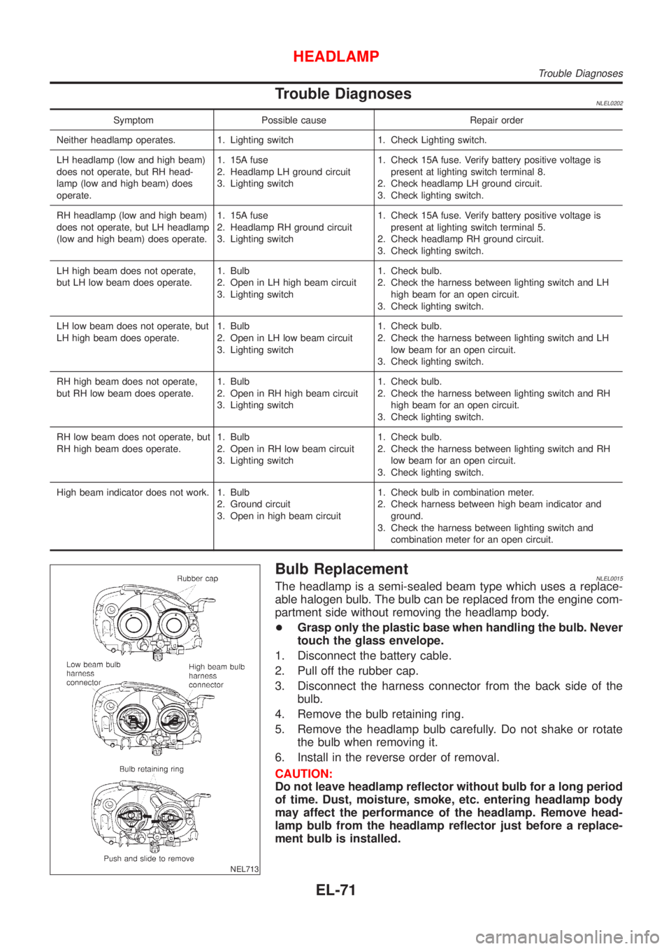
NEL713
Bulb ReplacementNLEL0015The headlamp is a semi-sealed beam type which uses a replace-
able halogen bulb. The bulb can be replaced from the engine com-
partment side without removing the headlamp body.
+Grasp only the plastic base when handling the bulb. Never
touch the glass envelope.
1. Disconnect the battery cable.
2. Pull off the rubber cap.
3. Disconnect the harness connector from the back side of the
bulb.
4. Remove the bulb retaining ring.
5. Remove the headlamp bulb carefully. Do not shake or rotate
the bulb when removing it.
6. Install in the reverse order of removal.
CAUTION:
Do not leave headlamp reflector without bulb for a long period
of time. Dust, moisture, smoke, etc. entering headlamp body
may affect the performance of the headlamp. Remove head-
lamp bulb from the headlamp reflector just before a replace-
ment bulb is installed.
HEADLAMP
Trouble Diagnoses
EL-71
Page 1812 of 3051
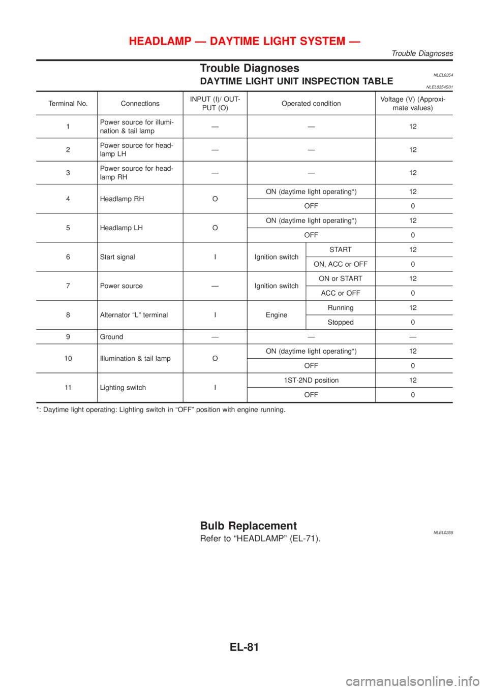
Trouble DiagnosesNLEL0354DAYTIME LIGHT UNIT INSPECTION TABLENLEL0354S01
Terminal No. ConnectionsINPUT (I)/ OUT-
PUT (O)Operated conditionVoltage (V) (Approxi-
mate values)
1Power source for illumi-
nation & tail lampÐÐ 12
2Power source for head-
lamp LHÐÐ 12
3Power source for head-
lamp RHÐÐ 12
4 Headlamp RH OON (daytime light operating*) 12
OFF 0
5 Headlamp LH OON (daytime light operating*) 12
OFF 0
6 Start signal I Ignition switchSTART 12
ON, ACC or OFF 0
7 Power source Ð Ignition switchON or START 12
ACC or OFF 0
8 Alternator ªLº terminal I EngineRunning 12
Stopped 0
9 Ground Ð Ð Ð
10 Illumination & tail lamp OON (daytime light operating*) 12
OFF 0
11 Lighting switch I1ST´2ND position 12
OFF 0
*: Daytime light operating: Lighting switch in ªOFFº position with engine running.
Bulb ReplacementNLEL0355Refer to ªHEADLAMPº (EL-71).
HEADLAMP Ð DAYTIME LIGHT SYSTEM Ð
Trouble Diagnoses
EL-81
Page 1828 of 3051
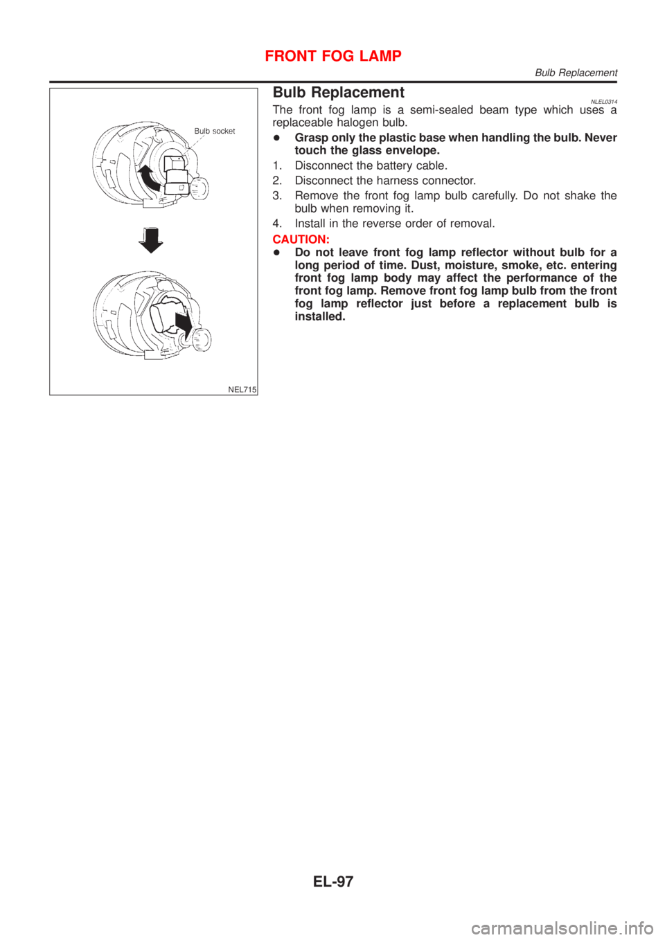
NEL715
Bulb ReplacementNLEL0314The front fog lamp is a semi-sealed beam type which uses a
replaceable halogen bulb.
+Grasp only the plastic base when handling the bulb. Never
touch the glass envelope.
1. Disconnect the battery cable.
2. Disconnect the harness connector.
3. Remove the front fog lamp bulb carefully. Do not shake the
bulb when removing it.
4. Install in the reverse order of removal.
CAUTION:
+Do not leave front fog lamp reflector without bulb for a
long period of time. Dust, moisture, smoke, etc. entering
front fog lamp body may affect the performance of the
front fog lamp. Remove front fog lamp bulb from the front
fog lamp reflector just before a replacement bulb is
installed.
FRONT FOG LAMP
Bulb Replacement
EL-97
Page 1837 of 3051
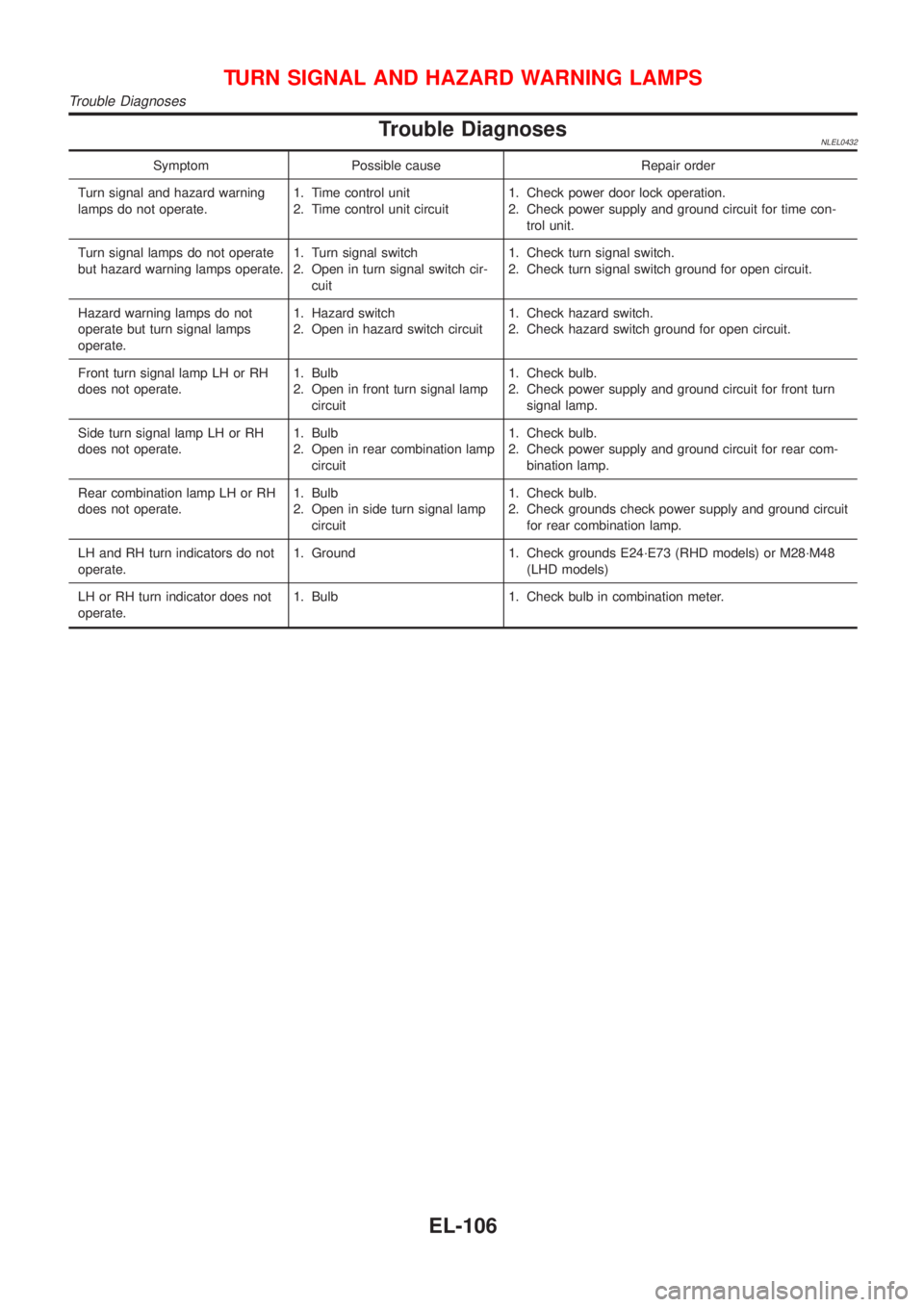
Trouble DiagnosesNLEL0432
Symptom Possible cause Repair order
Turn signal and hazard warning
lamps do not operate.1. Time control unit
2. Time control unit circuit1. Check power door lock operation.
2. Check power supply and ground circuit for time con-
trol unit.
Turn signal lamps do not operate
but hazard warning lamps operate.1. Turn signal switch
2. Open in turn signal switch cir-
cuit1. Check turn signal switch.
2. Check turn signal switch ground for open circuit.
Hazard warning lamps do not
operate but turn signal lamps
operate.1. Hazard switch
2. Open in hazard switch circuit1. Check hazard switch.
2. Check hazard switch ground for open circuit.
Front turn signal lamp LH or RH
does not operate.1. Bulb
2. Open in front turn signal lamp
circuit1. Check bulb.
2. Check power supply and ground circuit for front turn
signal lamp.
Side turn signal lamp LH or RH
does not operate.1. Bulb
2. Open in rear combination lamp
circuit1. Check bulb.
2. Check power supply and ground circuit for rear com-
bination lamp.
Rear combination lamp LH or RH
does not operate.1. Bulb
2. Open in side turn signal lamp
circuit1. Check bulb.
2. Check grounds check power supply and ground circuit
for rear combination lamp.
LH and RH turn indicators do not
operate.1. Ground 1. Check grounds E24´E73 (RHD models) or M28´M48
(LHD models)
LH or RH turn indicator does not
operate.1. Bulb 1. Check bulb in combination meter.
TURN SIGNAL AND HAZARD WARNING LAMPS
Trouble Diagnoses
EL-106
Page 1876 of 3051
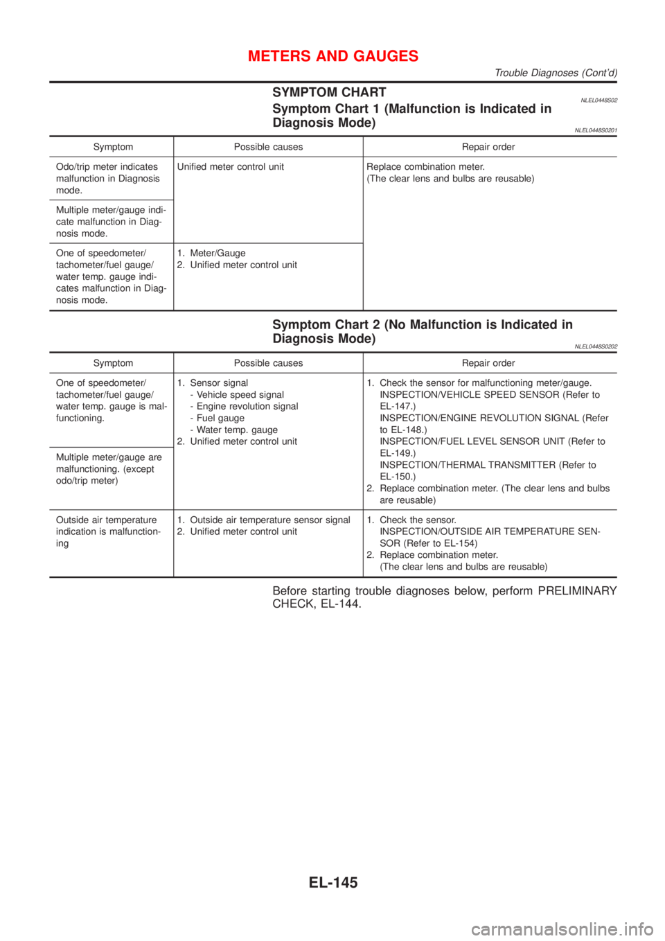
SYMPTOM CHARTNLEL0448S02Symptom Chart 1 (Malfunction is Indicated in
Diagnosis Mode)
NLEL0448S0201
Symptom Possible causes Repair order
Odo/trip meter indicates
malfunction in Diagnosis
mode.Unified meter control unit Replace combination meter.
(The clear lens and bulbs are reusable)
Multiple meter/gauge indi-
cate malfunction in Diag-
nosis mode.
One of speedometer/
tachometer/fuel gauge/
water temp. gauge indi-
cates malfunction in Diag-
nosis mode.1. Meter/Gauge
2. Unified meter control unit
Symptom Chart 2 (No Malfunction is Indicated in
Diagnosis Mode)
NLEL0448S0202
Symptom Possible causes Repair order
One of speedometer/
tachometer/fuel gauge/
water temp. gauge is mal-
functioning.1. Sensor signal
- Vehicle speed signal
- Engine revolution signal
- Fuel gauge
- Water temp. gauge
2. Unified meter control unit1. Check the sensor for malfunctioning meter/gauge.
INSPECTION/VEHICLE SPEED SENSOR (Refer to
EL-147.)
INSPECTION/ENGINE REVOLUTION SIGNAL (Refer
to EL-148.)
INSPECTION/FUEL LEVEL SENSOR UNIT (Refer to
EL-149.)
INSPECTION/THERMAL TRANSMITTER (Refer to
EL-150.)
2. Replace combination meter. (The clear lens and bulbs
are reusable) Multiple meter/gauge are
malfunctioning. (except
odo/trip meter)
Outside air temperature
indication is malfunction-
ing1. Outside air temperature sensor signal
2. Unified meter control unit1. Check the sensor.
INSPECTION/OUTSIDE AIR TEMPERATURE SEN-
SOR (Refer to EL-154)
2. Replace combination meter.
(The clear lens and bulbs are reusable)
Before starting trouble diagnoses below, perform PRELIMINARY
CHECK, EL-144.
METERS AND GAUGES
Trouble Diagnoses (Cont'd)
EL-145