2001 NISSAN ALMERA TINO stop start
[x] Cancel search: stop startPage 981 of 3051
SEF706Y
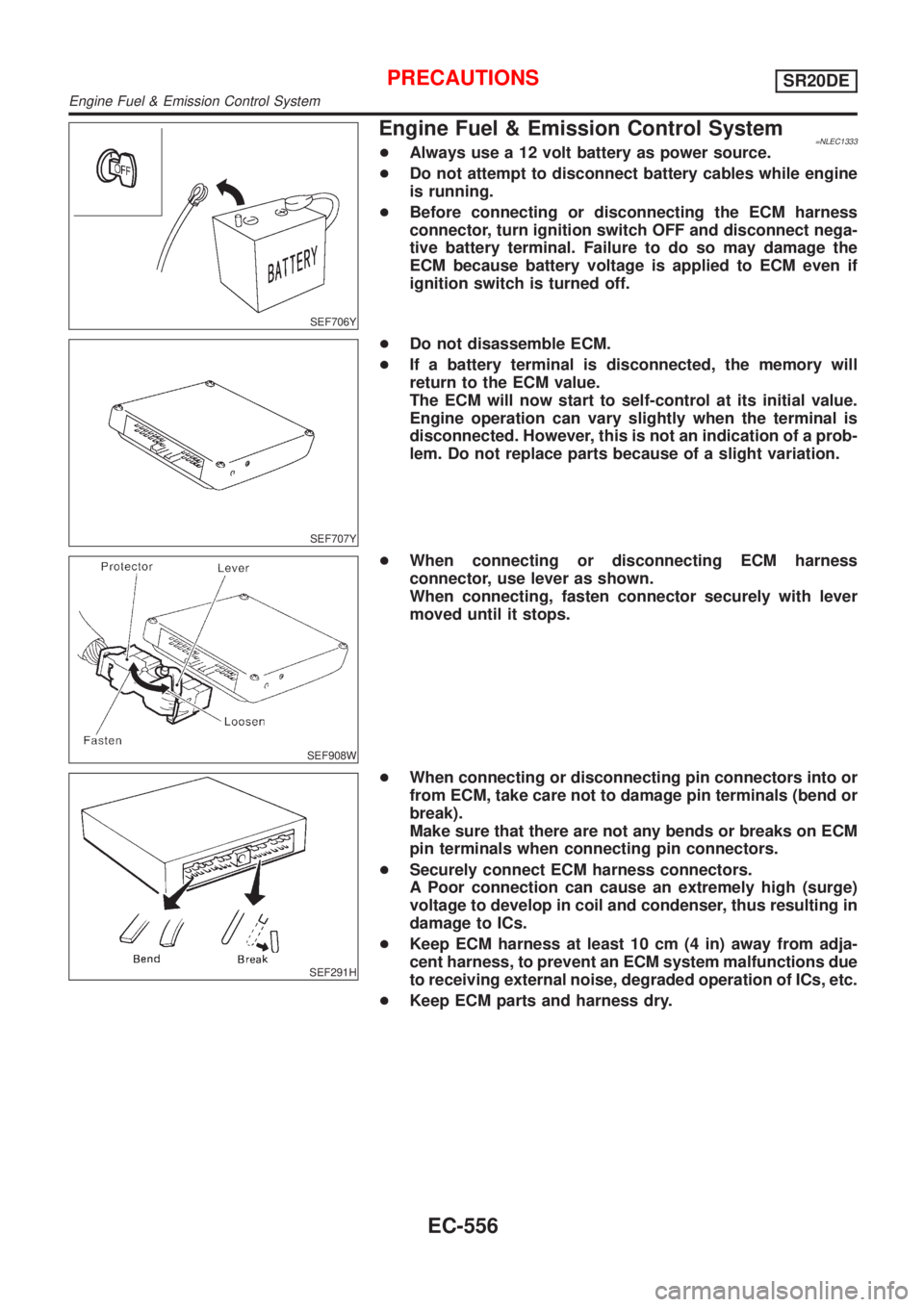
Engine Fuel & Emission Control System=NLEC1333+Always use a 12 volt battery as power source.
+Do not attempt to disconnect battery cables while engine
is running.
+Before connecting or disconnecting the ECM harness
connector, turn ignition switch OFF and disconnect nega-
tive battery terminal. Failure to do so may damage the
ECM because battery voltage is applied to ECM even if
ignition switch is turned off.
SEF707Y
+Do not disassemble ECM.
+If a battery terminal is disconnected, the memory will
return to the ECM value.
The ECM will now start to self-control at its initial value.
Engine operation can vary slightly when the terminal is
disconnected. However, this is not an indication of a prob-
lem. Do not replace parts because of a slight variation.
SEF908W
+When connecting or disconnecting ECM harness
connector, use lever as shown.
When connecting, fasten connector securely with lever
moved until it stops.
SEF291H
+When connecting or disconnecting pin connectors into or
from ECM, take care not to damage pin terminals (bend or
break).
Make sure that there are not any bends or breaks on ECM
pin terminals when connecting pin connectors.
+Securely connect ECM harness connectors.
A Poor connection can cause an extremely high (surge)
voltage to develop in coil and condenser, thus resulting in
damage to ICs.
+Keep ECM harness at least 10 cm (4 in) away from adja-
cent harness, to prevent an ECM system malfunctions due
to receiving external noise, degraded operation of ICs, etc.
+Keep ECM parts and harness dry.
PRECAUTIONSSR20DE
Engine Fuel & Emission Control System
EC-556
Page 995 of 3051
Mixture Ratio Feedback Control (Closed loop control)NLEC1342S04
SEF336WA
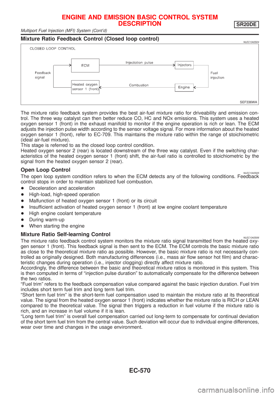
The mixture ratio feedback system provides the best air-fuel mixture ratio for driveability and emission con-
trol. The three way catalyst can then better reduce CO, HC and NOx emissions. This system uses a heated
oxygen sensor 1 (front) in the exhaust manifold to monitor if the engine operation is rich or lean. The ECM
adjusts the injection pulse width according to the sensor voltage signal. For more information about the heated
oxygen sensor 1 (front), refer to EC-709. This maintains the mixture ratio within the range of stoichiometric
(ideal air-fuel mixture).
This stage is referred to as the closed loop control condition.
Heated oxygen sensor 2 (rear) is located downstream of the three way catalyst. Even if the switching char-
acteristics of the heated oxygen sensor 1 (front) shift, the air-fuel ratio is controlled to stoichiometric by the
signal from the heated oxygen sensor 2 (rear).
Open Loop ControlNLEC1342S05The open loop system condition refers to when the ECM detects any of the following conditions. Feedback
control stops in order to maintain stabilized fuel combustion.
+Deceleration and acceleration
+High-load, high-speed operation
+Malfunction of heated oxygen sensor 1 (front) or its circuit
+Insufficient activation of heated oxygen sensor 1 (front) at low engine coolant temperature
+High engine coolant temperature
+During warm-up
+When starting the engine
Mixture Ratio Self-learning ControlNLEC1342S06The mixture ratio feedback control system monitors the mixture ratio signal transmitted from the heated oxy-
gen sensor 1 (front). This feedback signal is then sent to the ECM. The ECM controls the basic mixture ratio
as close to the theoretical mixture ratio as possible. However, the basic mixture ratio is not necessarily con-
trolled as originally designed. Both manufacturing differences (i.e., mass air flow sensor hot film) and charac-
teristic changes during operation (i.e., injector clogging) directly affect mixture ratio.
Accordingly, the difference between the basic and theoretical mixture ratios is monitored in this system. This
is then computed in terms of ªinjection pulse durationº to automatically compensate for the difference between
the two ratios.
ªFuel trimº refers to the feedback compensation value compared against the basic injection duration. Fuel trim
includes short term fuel trim and long term fuel trim.
ªShort term fuel trimº is the short-term fuel compensation used to maintain the mixture ratio at its theoretical
value. The signal from the heated oxygen sensor 1 (front) indicates whether the mixture ratio is RICH or LEAN
compared to the theoretical value. The signal then triggers a reduction in fuel volume if the mixture ratio is
rich, and an increase in fuel volume if it is lean.
ªLong term fuel trimº is overall fuel compensation carried out long-term to compensate for continual deviation
of the short term fuel trim from the central value. Such deviation will occur due to individual engine differences,
wear over time and changes in the usage environment.
ENGINE AND EMISSION BASIC CONTROL SYSTEM
DESCRIPTION
SR20DE
Multiport Fuel Injection (MFI) System (Cont'd)
EC-570
Page 1003 of 3051
If results are unsatisfactory, perform Fuel Pressure Regulator
Check, EC-578.
SEF718B
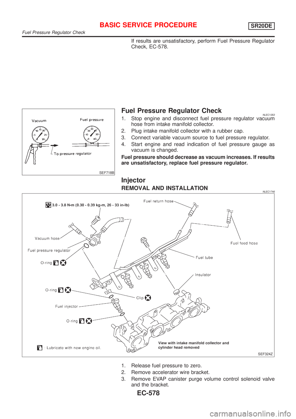
Fuel Pressure Regulator CheckNLEC13531. Stop engine and disconnect fuel pressure regulator vacuum
hose from intake manifold collector.
2. Plug intake manifold collector with a rubber cap.
3. Connect variable vacuum source to fuel pressure regulator.
4. Start engine and read indication of fuel pressure gauge as
vacuum is changed.
Fuel pressure should decrease as vacuum increases. If results
are unsatisfactory, replace fuel pressure regulator.
Injector
REMOVAL AND INSTALLATIONNLEC1746
SEF324Z
1. Release fuel pressure to zero.
2. Remove accelerator wire bracket.
3. Remove EVAP canister purge volume control solenoid valve
and the bracket.
BASIC SERVICE PROCEDURESR20DE
Fuel Pressure Regulator Check
EC-578
Page 1006 of 3051
SEF217Z
SEF454Y
SEF455Y
Idle Air Volume LearningNLEC1358DESCRIPTIONNLEC1358S01ªIdle Air Volume Learningº is an operation to learn the idle air vol-
ume that keeps each engine within the specific range. It must be
performed under any of the following conditions:
+Each time IACV-AAC valve, throttle body or ECM is replaced.
+Idle speed or ignition timing is out of specification.
PRE-CONDITIONINGNLEC1358S02Before performing ªIdle Air Volume Learningº, make sure that all of
the following conditions are satisfied.
Learning will be cancelled if any of the following conditions are
missed for even a moment.
+Battery voltage: More than 12.9V (At idle)
+Engine coolant temperature: 70 - 95ÉC (158 - 203ÉF)
+PNP switch: ON
+Electric load switch: OFF
(Air conditioner, headlamp, rear window defogger)
On vehicles equipped with daytime light systems, set lighting
switch to the 1st position to light only small lamps.
+Cooling fan motor: Not operating
+Steering wheel: Neutral (Straight-ahead position)
+Vehicle speed: Stopped
+Transmission: Warmed-up
For models with CONSULT-II, drive vehicle until ªFLUID TEMP
SEº in ªDATA MONITORº mode of ªCVTº indicates less than
0.9V.
For models without CONSULT-II, drive vehicle for 10 minutes.
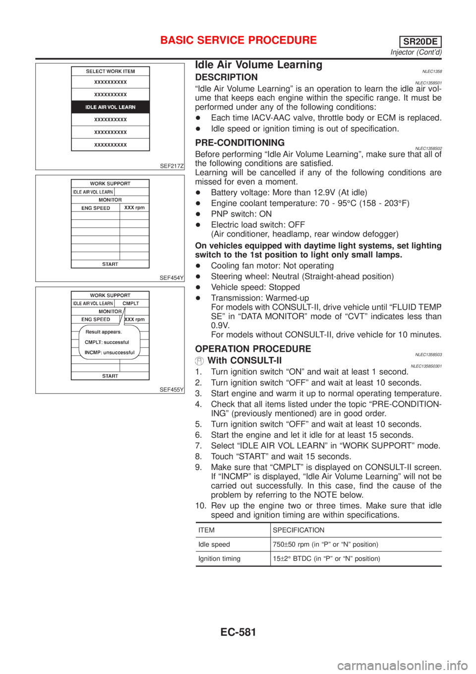
OPERATION PROCEDURENLEC1358S03With CONSULT-IINLEC1358S03011. Turn ignition switch ªONº and wait at least 1 second.
2. Turn ignition switch ªOFFº and wait at least 10 seconds.
3. Start engine and warm it up to normal operating temperature.
4. Check that all items listed under the topic ªPRE-CONDITION-
INGº (previously mentioned) are in good order.
5. Turn ignition switch ªOFFº and wait at least 10 seconds.
6. Start the engine and let it idle for at least 15 seconds.
7. Select ªIDLE AIR VOL LEARNº in ªWORK SUPPORTº mode.
8. Touch ªSTARTº and wait 15 seconds.
9. Make sure that ªCMPLTº is displayed on CONSULT-II screen.
If ªINCMPº is displayed, ªIdle Air Volume Learningº will not be
carried out successfully. In this case, find the cause of the
problem by referring to the NOTE below.
10. Rev up the engine two or three times. Make sure that idle
speed and ignition timing are within specifications.
ITEM SPECIFICATION
Idle speed 750±50 rpm (in ªPº or ªNº position)
Ignition timing 15±2É BTDC (in ªPº or ªNº position)
BASIC SERVICE PROCEDURESR20DE
Injector (Cont'd)
EC-581
Page 1035 of 3051
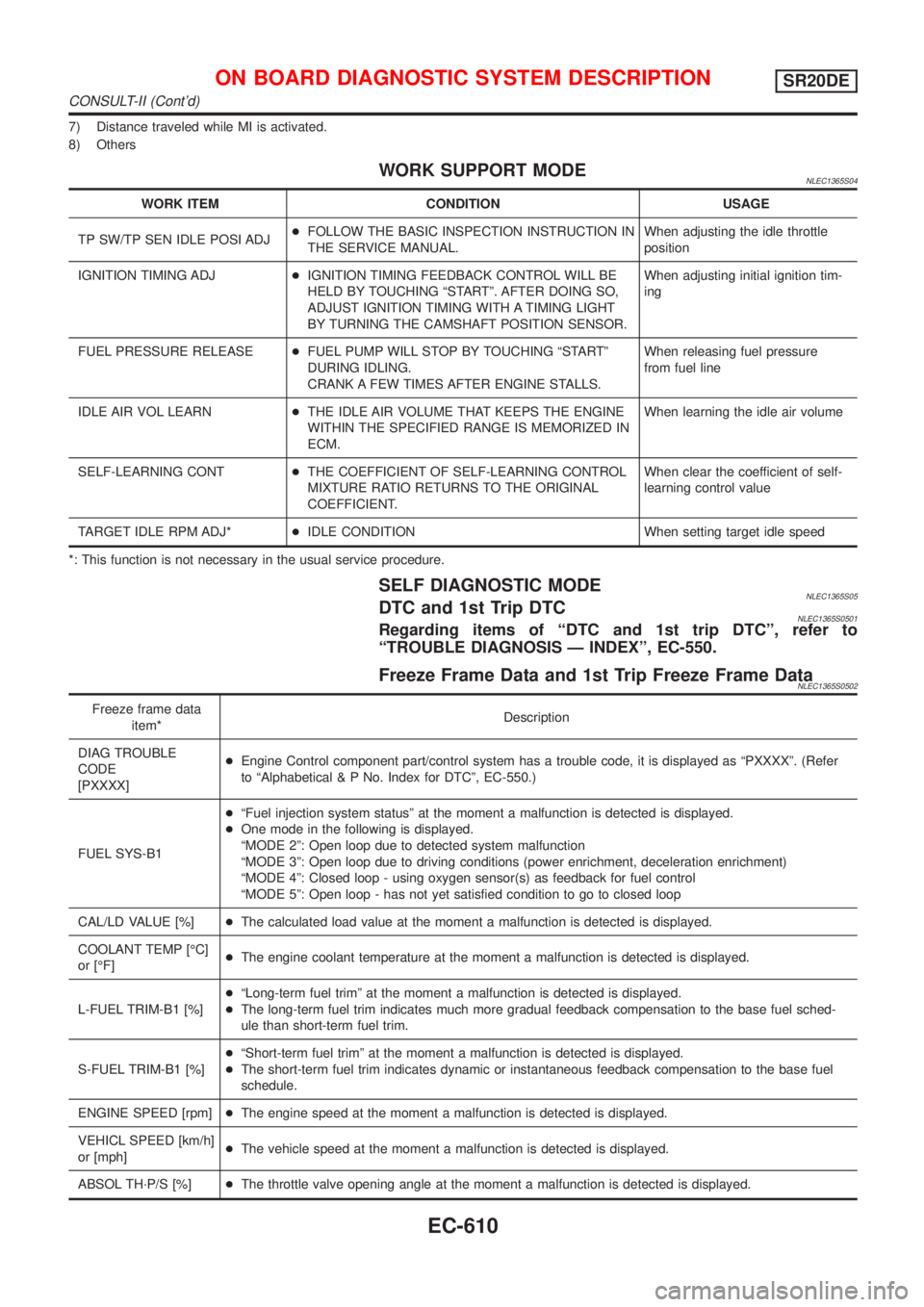
7) Distance traveled while MI is activated.
8) Others
WORK SUPPORT MODENLEC1365S04
WORK ITEM CONDITION USAGE
TP SW/TP SEN IDLE POSI ADJ+FOLLOW THE BASIC INSPECTION INSTRUCTION IN
THE SERVICE MANUAL.When adjusting the idle throttle
position
IGNITION TIMING ADJ+IGNITION TIMING FEEDBACK CONTROL WILL BE
HELD BY TOUCHING ªSTARTº. AFTER DOING SO,
ADJUST IGNITION TIMING WITH A TIMING LIGHT
BY TURNING THE CAMSHAFT POSITION SENSOR.When adjusting initial ignition tim-
ing
FUEL PRESSURE RELEASE+FUEL PUMP WILL STOP BY TOUCHING ªSTARTº
DURING IDLING.
CRANK A FEW TIMES AFTER ENGINE STALLS.When releasing fuel pressure
from fuel line
IDLE AIR VOL LEARN+THE IDLE AIR VOLUME THAT KEEPS THE ENGINE
WITHIN THE SPECIFIED RANGE IS MEMORIZED IN
ECM.When learning the idle air volume
SELF-LEARNING CONT+THE COEFFICIENT OF SELF-LEARNING CONTROL
MIXTURE RATIO RETURNS TO THE ORIGINAL
COEFFICIENT.When clear the coefficient of self-
learning control value
TARGET IDLE RPM ADJ*+IDLE CONDITION When setting target idle speed
*: This function is not necessary in the usual service procedure.
SELF DIAGNOSTIC MODENLEC1365S05DTC and 1st Trip DTCNLEC1365S0501Regarding items of ªDTC and 1st trip DTCº, refer to
ªTROUBLE DIAGNOSIS Ð INDEXº, EC-550.
Freeze Frame Data and 1st Trip Freeze Frame DataNLEC1365S0502
Freeze frame data
item*Description
DIAG TROUBLE
CODE
[PXXXX]+Engine Control component part/control system has a trouble code, it is displayed as ªPXXXXº. (Refer
to ªAlphabetical & P No. Index for DTCº, EC-550.)
FUEL SYS-B1+ªFuel injection system statusº at the moment a malfunction is detected is displayed.
+One mode in the following is displayed.
ªMODE 2º: Open loop due to detected system malfunction
ªMODE 3º: Open loop due to driving conditions (power enrichment, deceleration enrichment)
ªMODE 4º: Closed loop - using oxygen sensor(s) as feedback for fuel control
ªMODE 5º: Open loop - has not yet satisfied condition to go to closed loop
CAL/LD VALUE [%]+The calculated load value at the moment a malfunction is detected is displayed.
COOLANT TEMP [ÉC]
or [ÉF]+The engine coolant temperature at the moment a malfunction is detected is displayed.
L-FUEL TRIM-B1 [%]+ªLong-term fuel trimº at the moment a malfunction is detected is displayed.
+The long-term fuel trim indicates much more gradual feedback compensation to the base fuel sched-
ule than short-term fuel trim.
S-FUEL TRIM-B1 [%]+ªShort-term fuel trimº at the moment a malfunction is detected is displayed.
+The short-term fuel trim indicates dynamic or instantaneous feedback compensation to the base fuel
schedule.
ENGINE SPEED [rpm]+The engine speed at the moment a malfunction is detected is displayed.
VEHICL SPEED [km/h]
or [mph]+The vehicle speed at the moment a malfunction is detected is displayed.
ABSOL TH´P/S [%]+The throttle valve opening angle at the moment a malfunction is detected is displayed.
ON BOARD DIAGNOSTIC SYSTEM DESCRIPTIONSR20DE
CONSULT-II (Cont'd)
EC-610
Page 1037 of 3051
![NISSAN ALMERA TINO 2001 Service Repair Manual Monitored item [Unit]ECM
input
signalsMain
signalsDescription Remarks
INT/A TEMP SE
[ÉC] or [ÉF]jj+The intake air temperature determined by the
signal voltage of the intake air temperature
sensor is NISSAN ALMERA TINO 2001 Service Repair Manual Monitored item [Unit]ECM
input
signalsMain
signalsDescription Remarks
INT/A TEMP SE
[ÉC] or [ÉF]jj+The intake air temperature determined by the
signal voltage of the intake air temperature
sensor is](/manual-img/5/57352/w960_57352-1036.png)
Monitored item [Unit]ECM
input
signalsMain
signalsDescription Remarks
INT/A TEMP SE
[ÉC] or [ÉF]jj+The intake air temperature determined by the
signal voltage of the intake air temperature
sensor is indicated.
EGR TEMP SEN [V]
(where fitted)jj+The signal voltage of the EGR temperature
sensor is displayed.
START SIGNAL
[ON/OFF]jj+Indicates [ON/OFF] condition from the starter
signal.+After starting the engine, [OFF] is
displayed regardless of the starter
signal.
CLSD THL POS
[ON/OFF]jj+Indicates idle position [ON/OFF] computed by
ECM according to the throttle position sensor
signal.
AIR COND SIG
[ON/OFF]jj+Indicates [ON/OFF] condition of the air condi-
tioner switch as determined by the air condi-
tioning signal.
P/N POSI SW
[ON/OFF]jj+Indicates [ON/OFF] condition from the PNP
switch signal.
PW/ST SIGNAL
[ON/OFF]jj+Indicates [ON/OFF] condition of the power
steering oil pressure switch determined by
the power steering oil pressure switch signal.
LOAD SIGNAL
[ON/OFF]jj+Indicates [ON/OFF] condition from the electri-
cal load signal and/or lighting switch.
ON ... rear defogger is operating and/or light-
ing switch is on.
OFF ... rear defogger is not operating and
lighting switch is not on.
IGNITION SW
[ON/OFF]j+Indicates [ON/OFF] condition from ignition
switch.
INJ PULSE-B1
[msec]j+Indicates the actual fuel injection pulse width
compensated by ECM according to the input
signals.+When the engine is stopped, a cer-
tain computed value is indicated.
IGN TIMING [BTDC]j+Indicates the ignition timing computed by
ECM according to the input signals.
CAL/LD VALUE [%]+ªCalculated load valueº indicates the value of
the current airflow divided by peak airflow.
ABSOL TH.P/S [%]+ªAbsolute throttle position sensorº indicates
the throttle opening computed by ECM
according to the signal voltage of the throttle
position sensor.
MASS AIRFLOW
[gm/s]+Indicates the mass airflow computed by ECM
according to the signal voltage of the mass
air flow sensor.
IACV-AAC/V [step]j+Indicates the IACV-AAC valve control value
computed by ECM according to the input sig-
nals.
PURG VOL C/V [%]+Indicates the EVAP canister purge volume
control solenoid valve computed by the ECM
according to the inpuct signals.
+The opening becomes larger as the value
increases.
ON BOARD DIAGNOSTIC SYSTEM DESCRIPTIONSR20DE
CONSULT-II (Cont'd)
EC-612
Page 1054 of 3051
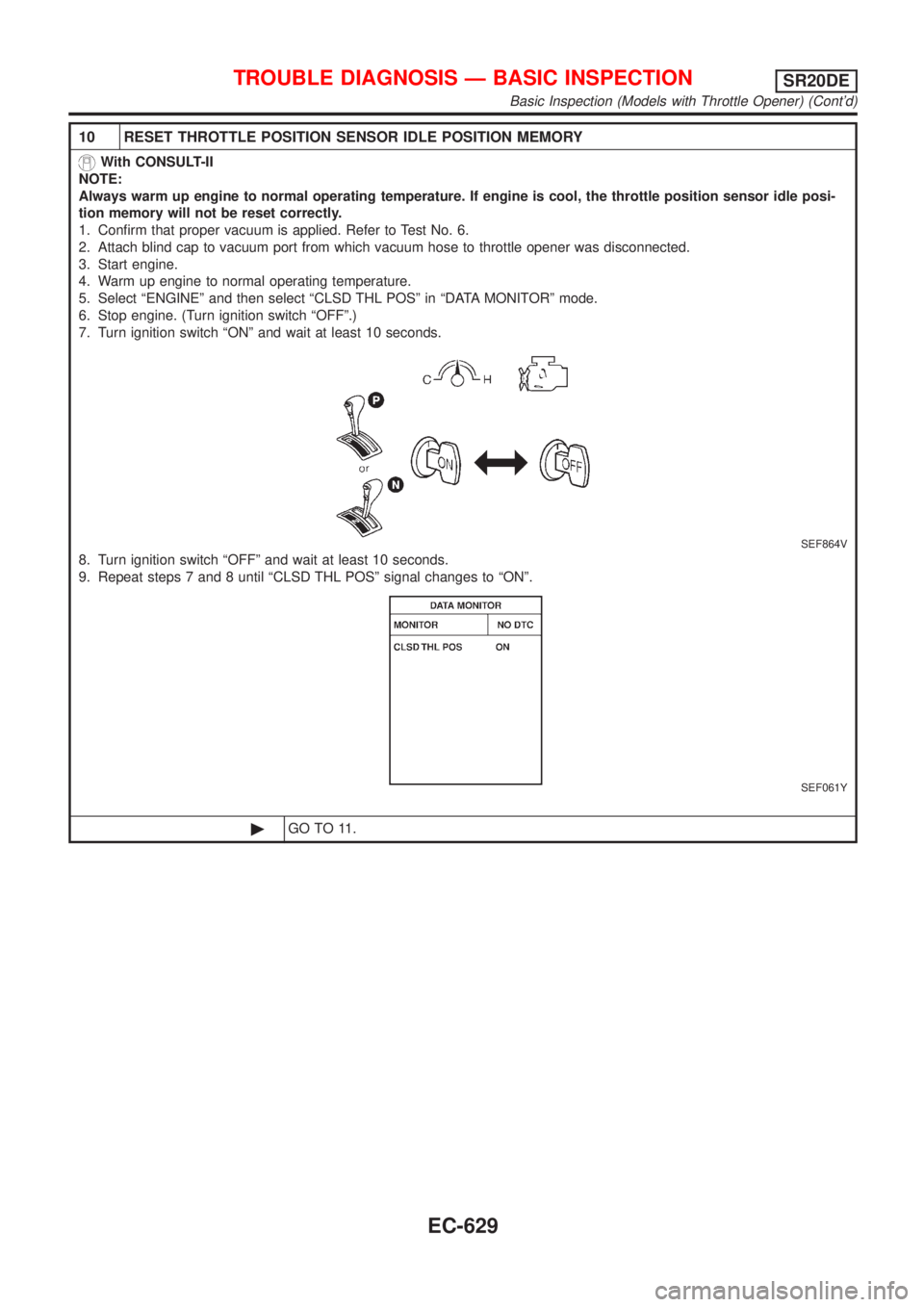
10 RESET THROTTLE POSITION SENSOR IDLE POSITION MEMORY
With CONSULT-II
NOTE:
Always warm up engine to normal operating temperature. If engine is cool, the throttle position sensor idle posi-
tion memory will not be reset correctly.
1. Confirm that proper vacuum is applied. Refer to Test No. 6.
2. Attach blind cap to vacuum port from which vacuum hose to throttle opener was disconnected.
3. Start engine.
4. Warm up engine to normal operating temperature.
5. Select ªENGINEº and then select ªCLSD THL POSº in ªDATA MONITORº mode.
6. Stop engine. (Turn ignition switch ªOFFº.)
7. Turn ignition switch ªONº and wait at least 10 seconds.
SEF864V
8. Turn ignition switch ªOFFº and wait at least 10 seconds.
9. Repeat steps 7 and 8 until ªCLSD THL POSº signal changes to ªONº.
SEF061Y
©GO TO 11.
TROUBLE DIAGNOSIS Ð BASIC INSPECTIONSR20DE
Basic Inspection (Models with Throttle Opener) (Cont'd)
EC-629
Page 1058 of 3051
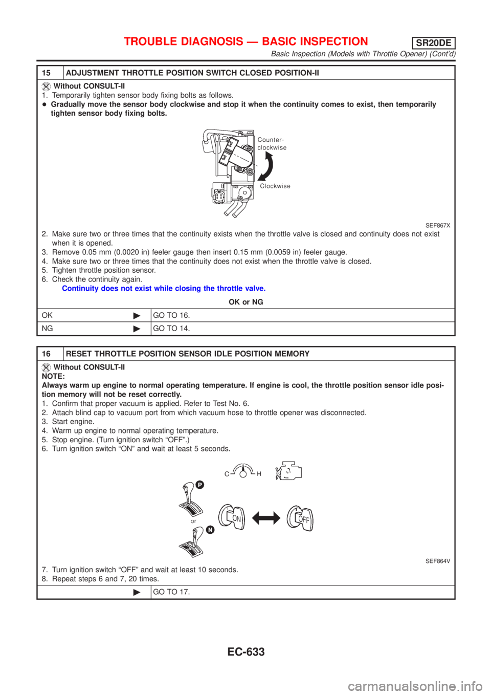
15 ADJUSTMENT THROTTLE POSITION SWITCH CLOSED POSITION-II
Without CONSULT-II
1. Temporarily tighten sensor body fixing bolts as follows.
+Gradually move the sensor body clockwise and stop it when the continuity comes to exist, then temporarily
tighten sensor body fixing bolts.
SEF867X
2. Make sure two or three times that the continuity exists when the throttle valve is closed and continuity does not exist
when it is opened.
3. Remove 0.05 mm (0.0020 in) feeler gauge then insert 0.15 mm (0.0059 in) feeler gauge.
4. Make sure two or three times that the continuity does not exist when the throttle valve is closed.
5. Tighten throttle position sensor.
6. Check the continuity again.
Continuity does not exist while closing the throttle valve.
OK or NG
OK©GO TO 16.
NG©GO TO 14.
16 RESET THROTTLE POSITION SENSOR IDLE POSITION MEMORY
Without CONSULT-II
NOTE:
Always warm up engine to normal operating temperature. If engine is cool, the throttle position sensor idle posi-
tion memory will not be reset correctly.
1. Confirm that proper vacuum is applied. Refer to Test No. 6.
2. Attach blind cap to vacuum port from which vacuum hose to throttle opener was disconnected.
3. Start engine.
4. Warm up engine to normal operating temperature.
5. Stop engine. (Turn ignition switch ªOFFº.)
6. Turn ignition switch ªONº and wait at least 5 seconds.
SEF864V
7. Turn ignition switch ªOFFº and wait at least 10 seconds.
8. Repeat steps 6 and 7, 20 times.
©GO TO 17.
TROUBLE DIAGNOSIS Ð BASIC INSPECTIONSR20DE
Basic Inspection (Models with Throttle Opener) (Cont'd)
EC-633