Page 1059 of 3051
17 CHECK IGNITION TIMING-I
Without CONSULT-II
1. Turn ignition switch ªOFFº.
2. Release vacuum from throttle opener.
3. Remove vacuum pump and vacuum hose from throttle opener.
4. Reinstall original vacuum hose to throttle opener securely.
5. Start engine and warm it up to normal operating temperature.
6. Stop engine and disconnect throttle position sensor harness connector.
SEF770Z
7. Start engine.
8. Check ignition timing at idle using a timing light.
SEF284G
Ignition timing:
15ɱ2É BTDC (in ªPº or ªNº position)
OK or NG
OK©GO TO 18.
NG©1. Adjust ignition timing by turning distributor.
2. GO TO 18.
TROUBLE DIAGNOSIS Ð BASIC INSPECTIONSR20DE
Basic Inspection (Models with Throttle Opener) (Cont'd)
EC-634
Page 1060 of 3051
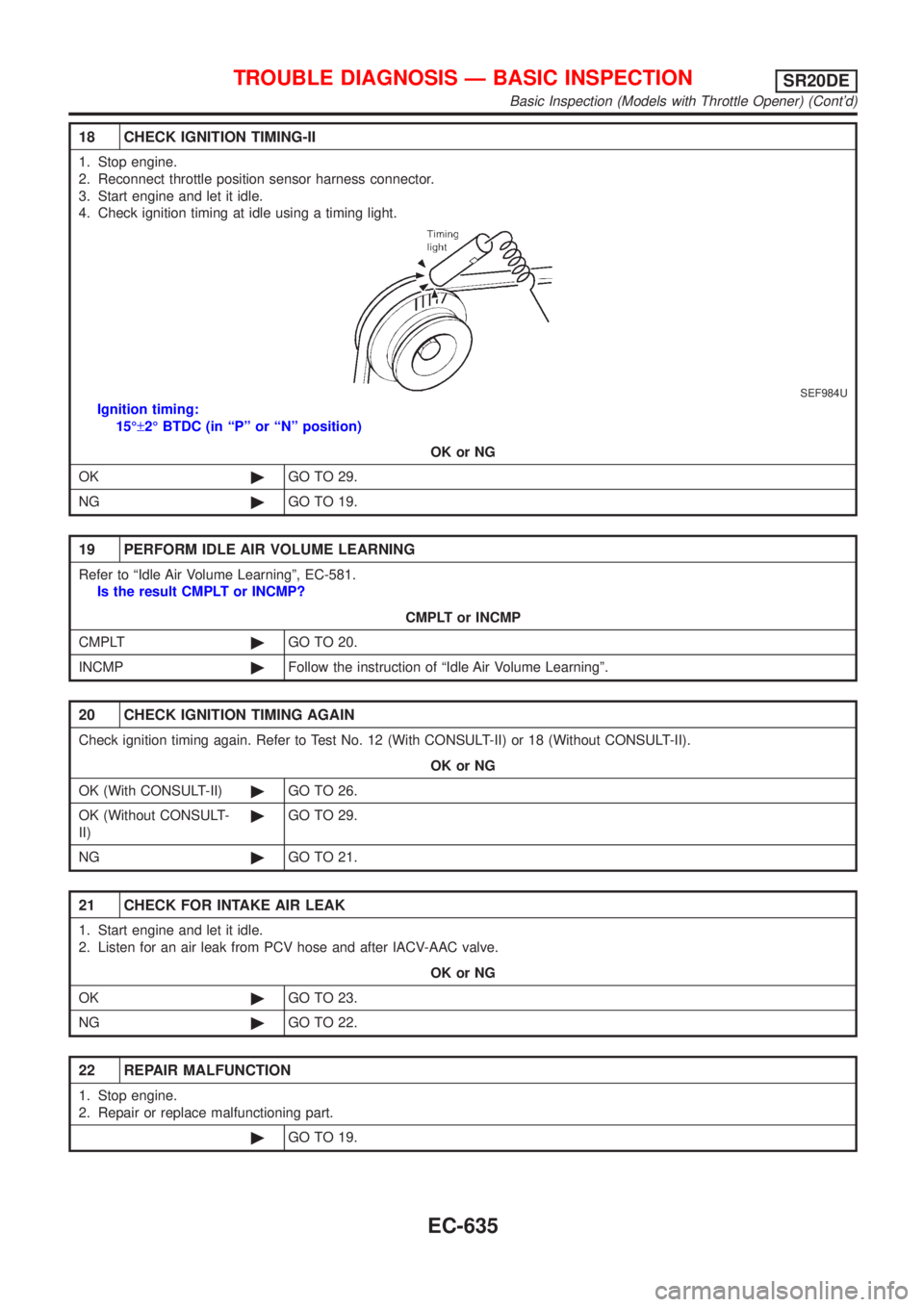
18 CHECK IGNITION TIMING-II
1. Stop engine.
2. Reconnect throttle position sensor harness connector.
3. Start engine and let it idle.
4. Check ignition timing at idle using a timing light.
SEF984U
Ignition timing:
15ɱ2É BTDC (in ªPº or ªNº position)
OK or NG
OK©GO TO 29.
NG©GO TO 19.
19 PERFORM IDLE AIR VOLUME LEARNING
Refer to ªIdle Air Volume Learningº, EC-581.
Is the result CMPLT or INCMP?
CMPLT or INCMP
CMPLT©GO TO 20.
INCMP©Follow the instruction of ªIdle Air Volume Learningº.
20 CHECK IGNITION TIMING AGAIN
Check ignition timing again. Refer to Test No. 12 (With CONSULT-II) or 18 (Without CONSULT-II).
OK or NG
OK (With CONSULT-II)©GO TO 26.
OK (Without CONSULT-
II)©GO TO 29.
NG©GO TO 21.
21 CHECK FOR INTAKE AIR LEAK
1. Start engine and let it idle.
2. Listen for an air leak from PCV hose and after IACV-AAC valve.
OK or NG
OK©GO TO 23.
NG©GO TO 22.
22 REPAIR MALFUNCTION
1. Stop engine.
2. Repair or replace malfunctioning part.
©GO TO 19.
TROUBLE DIAGNOSIS Ð BASIC INSPECTIONSR20DE
Basic Inspection (Models with Throttle Opener) (Cont'd)
EC-635
Page 1063 of 3051
Basic Inspection (Models without Throttle
Opener)
=NLEC1930Precaution:
Perform Basic Inspection without electrical or mechanical
loads applied;
+Headlamp switch is OFF,
+On vehicles equipped with daytime running light system, set
lighting switch to the 1st position to light only small lamps.
+Air conditioner switch is OFF,
+Rear window defogger switch is OFF,
+Steering wheel is in the straight-ahead position, etc.
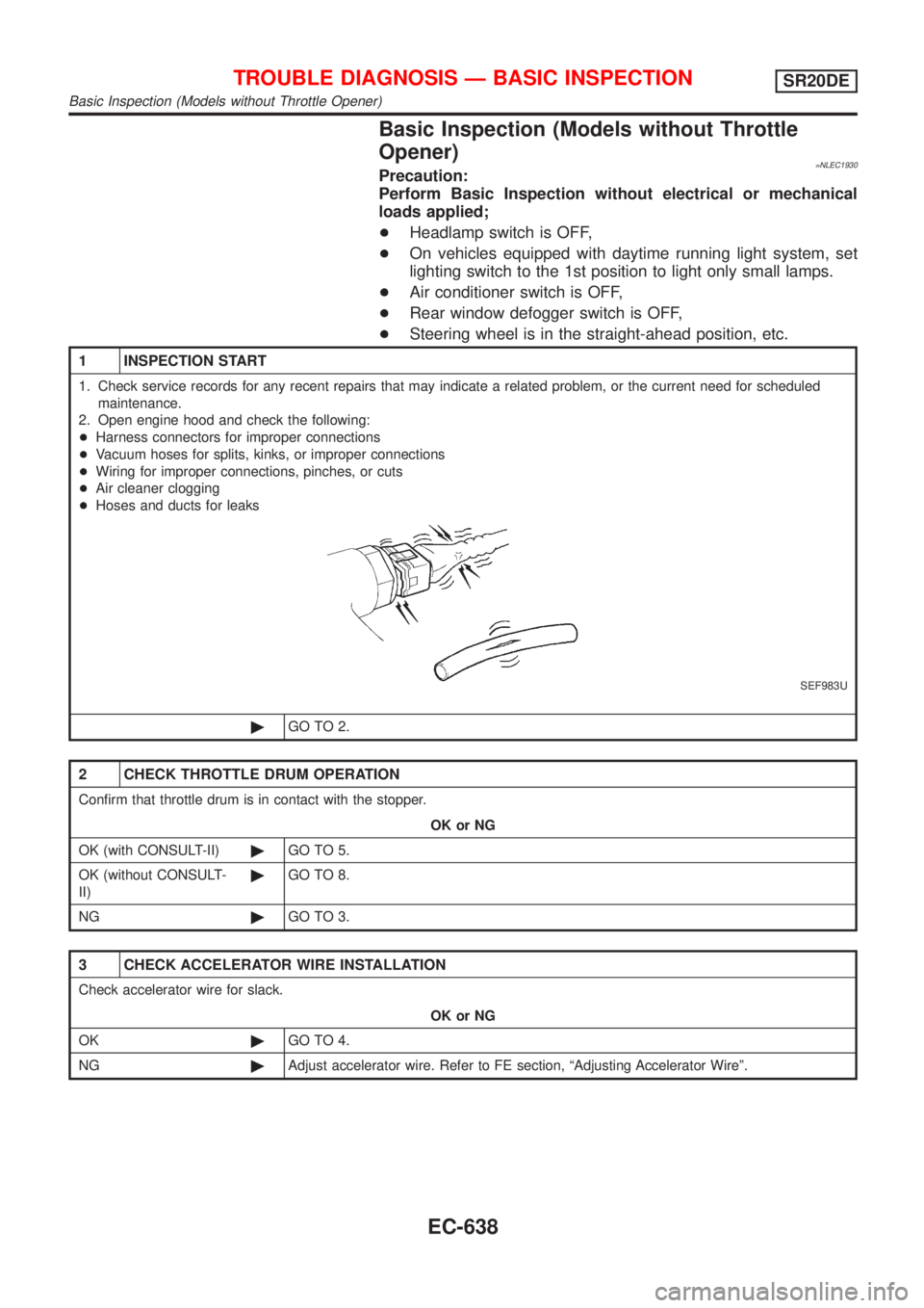
1 INSPECTION START
1. Check service records for any recent repairs that may indicate a related problem, or the current need for scheduled
maintenance.
2. Open engine hood and check the following:
+Harness connectors for improper connections
+Vacuum hoses for splits, kinks, or improper connections
+Wiring for improper connections, pinches, or cuts
+Air cleaner clogging
+Hoses and ducts for leaks
SEF983U
©GO TO 2.
2 CHECK THROTTLE DRUM OPERATION
Confirm that throttle drum is in contact with the stopper.
OK or NG
OK (with CONSULT-II)©GO TO 5.
OK (without CONSULT-
II)©GO TO 8.
NG©GO TO 3.
3 CHECK ACCELERATOR WIRE INSTALLATION
Check accelerator wire for slack.
OK or NG
OK©GO TO 4.
NG©Adjust accelerator wire. Refer to FE section, ªAdjusting Accelerator Wireº.
TROUBLE DIAGNOSIS Ð BASIC INSPECTIONSR20DE
Basic Inspection (Models without Throttle Opener)
EC-638
Page 1064 of 3051
4 CHECK THROTTLE VALVE OPERATION
1. Remove intake air ducts.
2. Check throttle valve operation when moving throttle drum by hand.
OK or NG
OK©Retighten the throttle drum fixing nuts.
NG©Clean the throttle body and throttle valve.
5 CHECK CLOSED THROTTLE POSITION SWITCH IDLE POSITION
With CONSULT-II
1. Start engine and warm it up to normal operating temperature.
2. Stop engine.
3. Turn ignition switch ªONº.
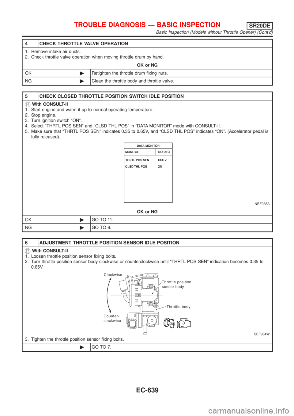
4. Select ªTHRTL POS SENº and ªCLSD THL POSº in ªDATA MONITORº mode with CONSULT-II.
5. Make sure that ªTHRTL POS SENº indicates 0.35 to 0.65V, and ªCLSD THL POSº indicates ªONº. (Accelerator pedal is
fully released).
NEF238A
OK or NG
OK©GO TO 11.
NG©GO TO 6.
6 ADJUSTMENT THROTTLE POSITION SENSOR IDLE POSITION
With CONSULT-II
1. Loosen throttle position sensor fixing bolts.
2. Turn throttle position sensor body clockwise or counterclockwise until ªTHRTL POS SENº indication becomes 0.35 to
0.65V.
SEF964W
3. Tighten the throttle position sensor fixing bolts.
©GO TO 7.
TROUBLE DIAGNOSIS Ð BASIC INSPECTIONSR20DE
Basic Inspection (Models without Throttle Opener) (Cont'd)
EC-639
Page 1065 of 3051
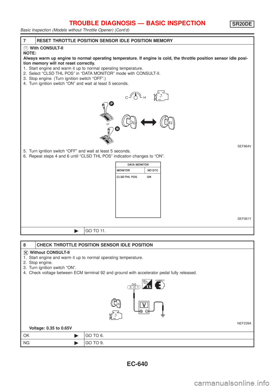
7 RESET THROTTLE POSITION SENSOR IDLE POSITION MEMORY
With CONSULT-II
NOTE:
Always warm up engine to normal operating temperature. If engine is cold, the throttle position sensor idle posi-
tion memory will not reset correctly.
1. Start engine and warm it up to normal operating temperature.
2. Select ªCLSD THL POSº in ªDATA MONITORº mode with CONSULT-II.
3. Stop engine. (Turn ignition switch ªOFFº.)
4. Turn ignition switch ªONº and wait at least 5 seconds.
SEF864V
5. Turn ignition switch ªOFFº and wait at least 5 seconds.
6. Repeat steps 4 and 6 until ªCLSD THL POSº indication changes to ªONº.
SEF061Y
©GO TO 11.
8 CHECK THROTTLE POSITION SENSOR IDLE POSITION
Without CONSULT-II
1. Start engine and warm it up to normal operating temperature.
2. Stop engine.
3. Turn ignition switch ªONº.
4. Check voltage between ECM terminal 92 and ground with accelerator pedal fully released.
NEF239A
Voltage: 0.35 to 0.65V
OK©GO TO 6.
NG©GO TO 9.
TROUBLE DIAGNOSIS Ð BASIC INSPECTIONSR20DE
Basic Inspection (Models without Throttle Opener) (Cont'd)
EC-640
Page 1066 of 3051
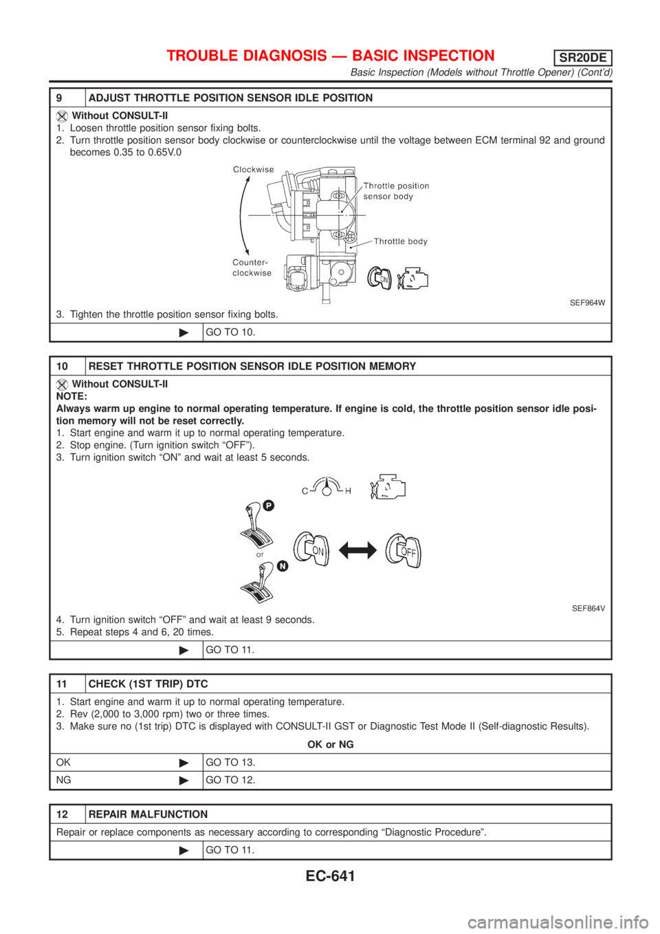
9 ADJUST THROTTLE POSITION SENSOR IDLE POSITION
Without CONSULT-II
1. Loosen throttle position sensor fixing bolts.
2. Turn throttle position sensor body clockwise or counterclockwise until the voltage between ECM terminal 92 and ground
becomes 0.35 to 0.65V.0
SEF964W
3. Tighten the throttle position sensor fixing bolts.
©GO TO 10.
10 RESET THROTTLE POSITION SENSOR IDLE POSITION MEMORY
Without CONSULT-II
NOTE:
Always warm up engine to normal operating temperature. If engine is cold, the throttle position sensor idle posi-
tion memory will not be reset correctly.
1. Start engine and warm it up to normal operating temperature.
2. Stop engine. (Turn ignition switch ªOFFº).
3. Turn ignition switch ªONº and wait at least 5 seconds.
SEF864V
4. Turn ignition switch ªOFFº and wait at least 9 seconds.
5. Repeat steps 4 and 6, 20 times.
©GO TO 11.
11 CHECK (1ST TRIP) DTC
1. Start engine and warm it up to normal operating temperature.
2. Rev (2,000 to 3,000 rpm) two or three times.
3. Make sure no (1st trip) DTC is displayed with CONSULT-II GST or Diagnostic Test Mode II (Self-diagnostic Results).
OK or NG
OK©GO TO 13.
NG©GO TO 12.
12 REPAIR MALFUNCTION
Repair or replace components as necessary according to corresponding ªDiagnostic Procedureº.
©GO TO 11.
TROUBLE DIAGNOSIS Ð BASIC INSPECTIONSR20DE
Basic Inspection (Models without Throttle Opener) (Cont'd)
EC-641
Page 1077 of 3051
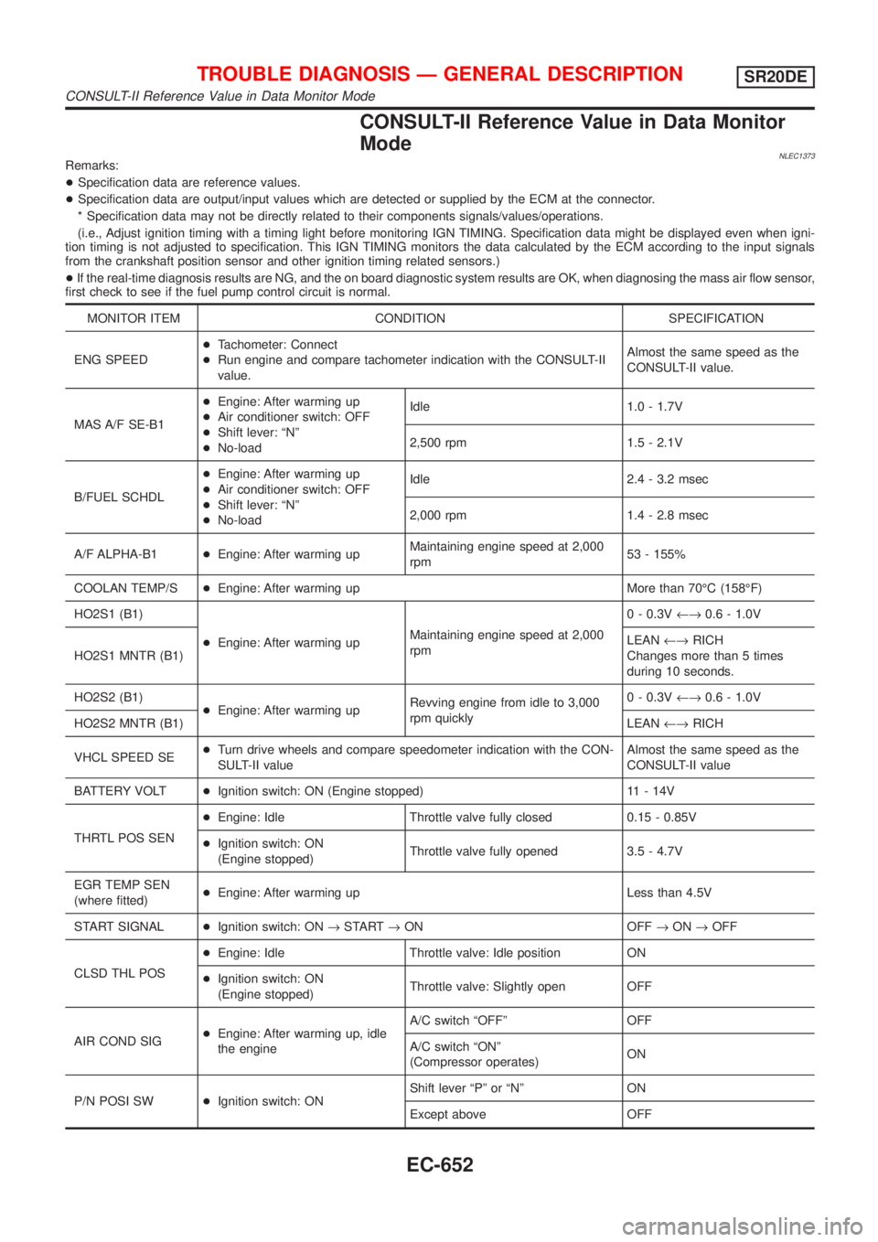
CONSULT-II Reference Value in Data Monitor
Mode
NLEC1373Remarks:
+Specification data are reference values.
+Specification data are output/input values which are detected or supplied by the ECM at the connector.
* Specification data may not be directly related to their components signals/values/operations.
(i.e., Adjust ignition timing with a timing light before monitoring IGN TIMING. Specification data might be displayed even when igni-
tion timing is not adjusted to specification. This IGN TIMING monitors the data calculated by the ECM according to the input signals
from the crankshaft position sensor and other ignition timing related sensors.)
+If the real-time diagnosis results are NG, and the on board diagnostic system results are OK, when diagnosing the mass air flow sensor,
first check to see if the fuel pump control circuit is normal.
MONITOR ITEM CONDITION SPECIFICATION
ENG SPEED+Tachometer: Connect
+Run engine and compare tachometer indication with the CONSULT-II
value.Almost the same speed as the
CONSULT-II value.
MAS A/F SE-B1+Engine: After warming up
+Air conditioner switch: OFF
+Shift lever: ªNº
+No-loadIdle 1.0 - 1.7V
2,500 rpm 1.5 - 2.1V
B/FUEL SCHDL+Engine: After warming up
+Air conditioner switch: OFF
+Shift lever: ªNº
+No-loadIdle 2.4 - 3.2 msec
2,000 rpm 1.4 - 2.8 msec
A/F ALPHA-B1+Engine: After warming upMaintaining engine speed at 2,000
rpm53 - 155%
COOLAN TEMP/S+Engine: After warming up More than 70ÉC (158ÉF)
HO2S1 (B1)
+Engine: After warming upMaintaining engine speed at 2,000
rpm0 - 0.3V¨0.6 - 1.0V
HO2S1 MNTR (B1)LEAN¨RICH
Changes more than 5 times
during 10 seconds.
HO2S2 (B1)
+Engine: After warming upRevving engine from idle to 3,000
rpm quickly0 - 0.3V¨0.6 - 1.0V
HO2S2 MNTR (B1)LEAN¨RICH
VHCL SPEED SE+Turn drive wheels and compare speedometer indication with the CON-
SULT-II valueAlmost the same speed as the
CONSULT-II value
BATTERY VOLT+Ignition switch: ON (Engine stopped) 11 - 14V
THRTL POS SEN+Engine: Idle Throttle valve fully closed 0.15 - 0.85V
+Ignition switch: ON
(Engine stopped)Throttle valve fully opened 3.5 - 4.7V
EGR TEMP SEN
(where fitted)+Engine: After warming up Less than 4.5V
START SIGNAL+Ignition switch: ON®START®ON OFF®ON®OFF
CLSD THL POS+Engine: Idle Throttle valve: Idle position ON
+Ignition switch: ON
(Engine stopped)Throttle valve: Slightly open OFF
AIR COND SIG+Engine: After warming up, idle
the engineA/C switch ªOFFº OFF
A/C switch ªONº
(Compressor operates)ON
P/N POSI SW+Ignition switch: ONShift lever ªPº or ªNº ON
Except above OFF
TROUBLE DIAGNOSIS Ð GENERAL DESCRIPTIONSR20DE
CONSULT-II Reference Value in Data Monitor Mode
EC-652
Page 1111 of 3051
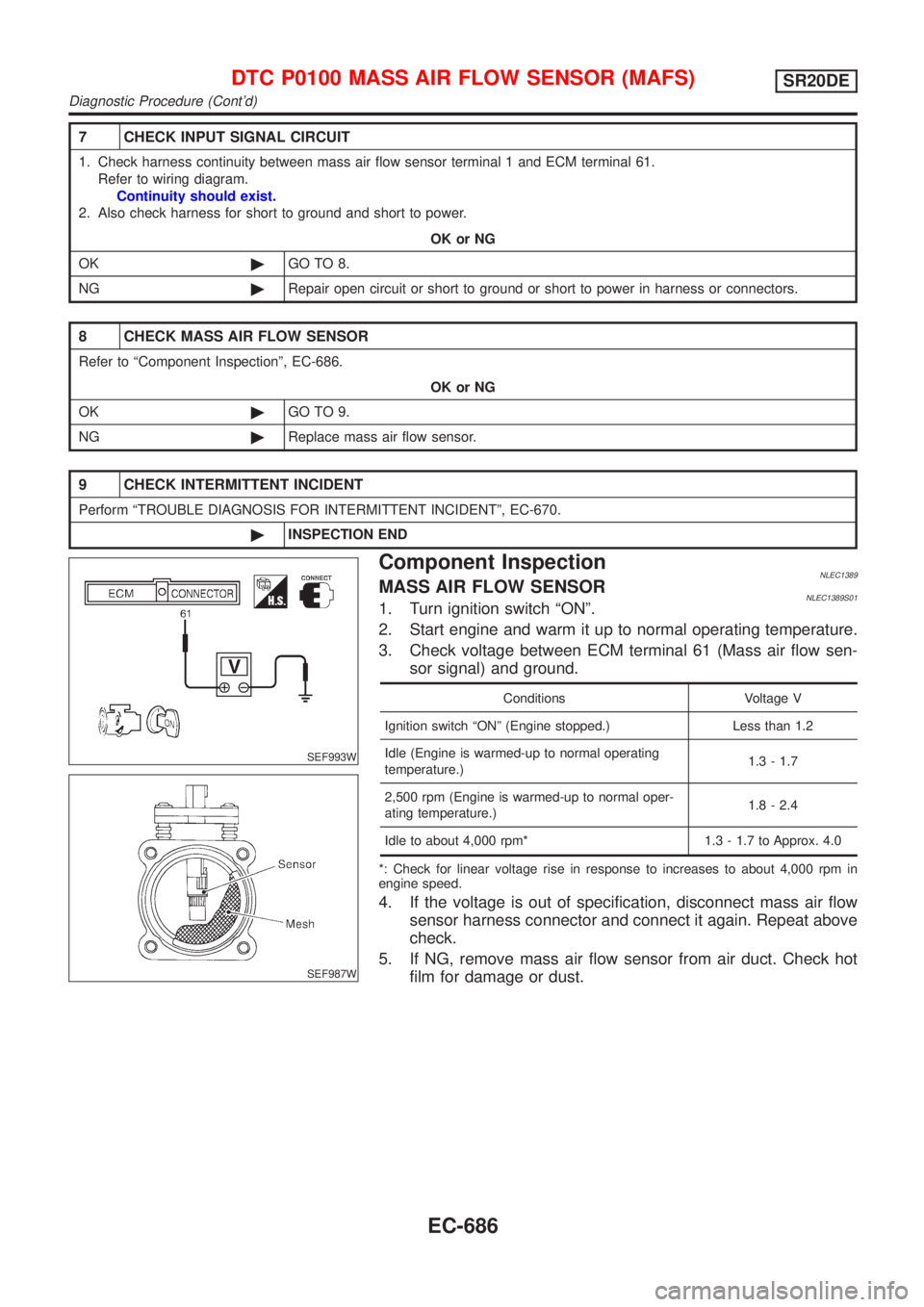
7 CHECK INPUT SIGNAL CIRCUIT
1. Check harness continuity between mass air flow sensor terminal 1 and ECM terminal 61.
Refer to wiring diagram.
Continuity should exist.
2. Also check harness for short to ground and short to power.
OK or NG
OK©GO TO 8.
NG©Repair open circuit or short to ground or short to power in harness or connectors.
8 CHECK MASS AIR FLOW SENSOR
Refer to ªComponent Inspectionº, EC-686.
OK or NG
OK©GO TO 9.
NG©Replace mass air flow sensor.
9 CHECK INTERMITTENT INCIDENT
Perform ªTROUBLE DIAGNOSIS FOR INTERMITTENT INCIDENTº, EC-670.
©INSPECTION END
SEF993W
SEF987W
Component InspectionNLEC1389MASS AIR FLOW SENSORNLEC1389S011. Turn ignition switch ªONº.
2. Start engine and warm it up to normal operating temperature.
3. Check voltage between ECM terminal 61 (Mass air flow sen-
sor signal) and ground.
Conditions Voltage V
Ignition switch ªONº (Engine stopped.) Less than 1.2
Idle (Engine is warmed-up to normal operating
temperature.)1.3 - 1.7
2,500 rpm (Engine is warmed-up to normal oper-
ating temperature.)1.8 - 2.4
Idle to about 4,000 rpm* 1.3 - 1.7 to Approx. 4.0
*: Check for linear voltage rise in response to increases to about 4,000 rpm in
engine speed.
4. If the voltage is out of specification, disconnect mass air flow
sensor harness connector and connect it again. Repeat above
check.
5. If NG, remove mass air flow sensor from air duct. Check hot
film for damage or dust.
DTC P0100 MASS AIR FLOW SENSOR (MAFS)SR20DE
Diagnostic Procedure (Cont'd)
EC-686