2001 NISSAN ALMERA TINO key
[x] Cancel search: keyPage 2544 of 3051

SEF289H
+Before starting repairs which do not require battery power:
Turn off ignition switch.
Disconnect the negative battery terminal.
SGI233
+To prevent serious burns:
Avoid contact with hot metal parts.
Do not remove the radiator cap when the engine is hot.
SGI234
+Before servicing the vehicle:
Protect fenders, upholstery and carpeting with appropriate cov-
ers.
Take caution that keys, buckles or buttons do not scratch paint.
+Clean all disassembled parts in the designated liquid or solvent
prior to inspection or assembly.
+Replace oil seals, gaskets, packings, O-rings, locking washers,
cotter pins, self-locking nuts, etc. with new ones.
+Replace inner and outer races of tapered roller bearings and
needle bearings as a set.
+Arrange the disassembled parts in accordance with their
assembled locations and sequence.
+Do not touch the terminals of electrical components which use
microcomputers (such as ECMs).
Static electricity may damage internal electronic components.
+After disconnecting vacuum or air hoses, attach a tag to indi-
cate the proper connection.
+Use only the fluids and lubricants specified in this manual.
+Use approved bonding agent, sealants or their equivalents
when required.
+Use tools and recommended special tools where specified for
safe and efficient service repairs.
+When repairing the fuel, oil, water, vacuum or exhaust
systems, check all affected lines for leaks.
+Dispose of drained oil or the solvent used for cleaning parts in
an appropriate manner.
PRECAUTIONS
Precautions (Cont’d)
GI-5
Page 2560 of 3051

NLGI0005
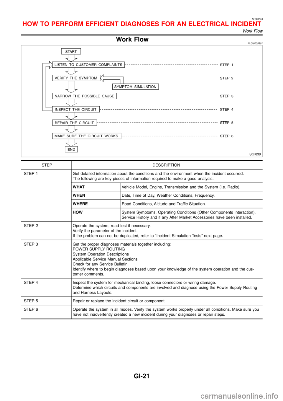
Work FlowNLGI0005S01
SGI838
STEP DESCRIPTION
STEP 1 Get detailed information about the conditions and the environment when the incident occurred.
The following are key pieces of information required to make a good analysis:
WHATVehicle Model, Engine, Transmission and the System (i.e. Radio).
WHENDate, Time of Day, Weather Conditions, Frequency.
WHERERoad Conditions, Altitude and Traffic Situation.
HOWSystem Symptoms, Operating Conditions (Other Components Interaction).
Service History and if any After Market Accessories have been installed.
STEP 2 Operate the system, road test if necessary.
Verify the parameter of the incident.
If the problem can not be duplicated, refer to“Incident Simulation Tests”next page.
STEP 3 Get the proper diagnoses materials together including:
POWER SUPPLY ROUTING
System Operation Descriptions
Applicable Service Manual Sections
Check for any Service Bulletin.
Identify where to begin diagnoses based upon your knowledge of the system operation and the cus-
tomer comments.
STEP 4 Inspect the system for mechanical binding, loose connectors or wiring damage.
Determine which circuits and components are involved and diagnose using the Power Supply Routing
and Harness Layouts.
STEP 5 Repair or replace the incident circuit or component.
STEP 6 Operate the system in all modes. Verify the system works properly under all conditions. Make sure you
have not inadvertently created a new incident during your diagnoses or repair steps.
HOW TO PERFORM EFFICIENT DIAGNOSES FOR AN ELECTRICAL INCIDENT
Work Flow
GI-21
Page 2565 of 3051

voltage; open is further down the circuit than the relay.
no voltage; open is between SW1 and relay (point B).
5) Close the relay and probe at the solenoid.
voltage; open is further down the circuit than the solenoid.
no voltage; open is between relay and solenoid (point C).
Any powered circuit can be diagnosed using the approach in the
above example.
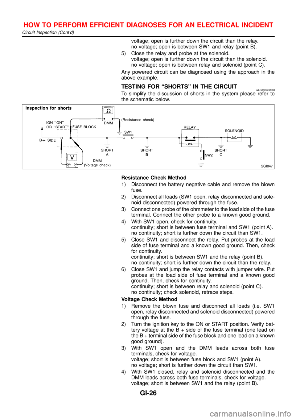
TESTING FOR“SHORTS”IN THE CIRCUITNLGI0005S0303To simplify the discussion of shorts in the system please refer to
the schematic below.
SGI847
Resistance Check Method
1) Disconnect the battery negative cable and remove the blown
fuse.
2) Disconnect all loads (SW1 open, relay disconnected and sole-
noid disconnected) powered through the fuse.
3) Connect one probe of the ohmmeter to the load side of the fuse
terminal. Connect the other probe to a known good ground.
4) With SW1 open, check for continuity.
continuity; short is between fuse terminal and SW1 (point A).
no continuity; short is further down the circuit than SW1.
5) Close SW1 and disconnect the relay. Put probes at the load
side of fuse terminal and a known good ground. Then, check
for continuity.
continuity; short is between SW1 and the relay (point B).
no continuity; short is further down the circuit than the relay.
6) Close SW1 and jump the relay contacts with jumper wire. Put
probes at the load side of fuse terminal and a known good
ground. Then, check for continuity.
continuity; short is between relay and solenoid (point C).
no continuity; check solenoid, retrace steps.
Voltage Check Method
1) Remove the blown fuse and disconnect all loads (i.e. SW1
open, relay disconnected and solenoid disconnected) powered
through the fuse.
2) Turn the ignition key to the ON or START position. Verify bat-
tery voltage at the B + side of the fuse terminal (one lead on
the B + terminal side of the fuse block and one lead on a known
good ground).
3) With SW1 open and the DMM leads across both fuse
terminals, check for voltage.
voltage; short is between fuse block and SW1 (point A).
no voltage; short is further down the circuit than SW1.
4) With SW1 closed, relay and solenoid disconnected and the
DMM leads across both fuse terminals, check for voltage.
voltage; short is between SW1 and the relay (point B).
HOW TO PERFORM EFFICIENT DIAGNOSES FOR AN ELECTRICAL INCIDENT
Circuit Inspection (Cont’d)
GI-26
Page 2571 of 3051

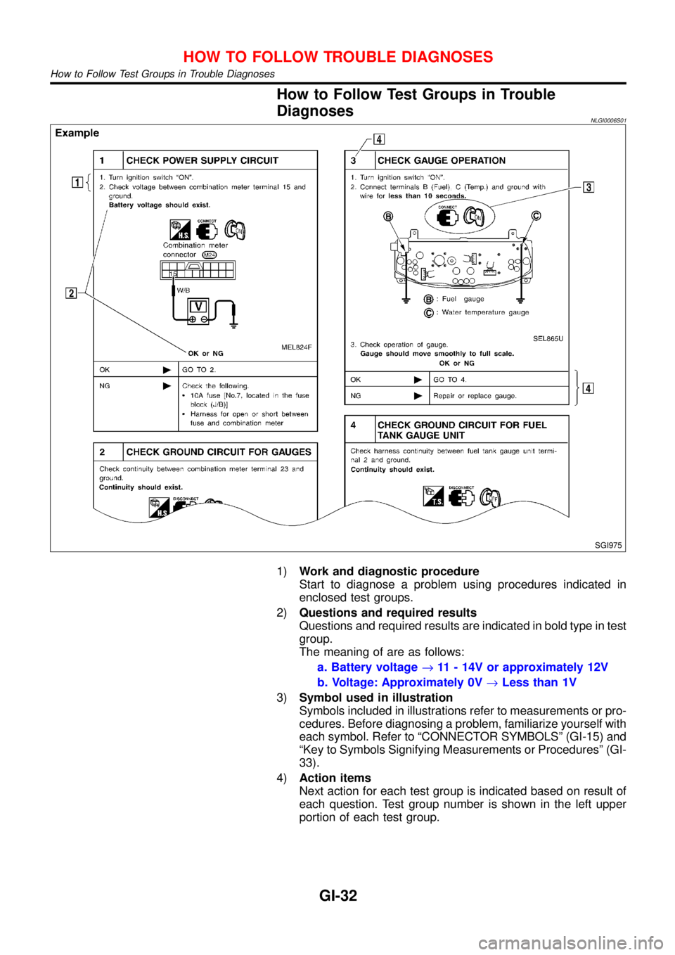
How to Follow Test Groups in Trouble
Diagnoses
NLGI0006S01
SGI975
1)Work and diagnostic procedure
Start to diagnose a problem using procedures indicated in
enclosed test groups.
2)Questions and required results
Questions and required results are indicated in bold type in test
group.
The meaning of are as follows:
a. Battery voltage→11 - 14V or approximately 12V
b. Voltage: Approximately 0V→Less than 1V
3)Symbol used in illustration
Symbols included in illustrations refer to measurements or pro-
cedures. Before diagnosing a problem, familiarize yourself with
each symbol. Refer to“CONNECTOR SYMBOLS”(GI-15) and
“Key to Symbols Signifying Measurements or Procedures”(GI-
33).
4)Action items
Next action for each test group is indicated based on result of
each question. Test group number is shown in the left upper
portion of each test group.
HOW TO FOLLOW TROUBLE DIAGNOSES
How to Follow Test Groups in Trouble Diagnoses
GI-32
Page 2572 of 3051

Key to Symbols Signifying Measurements or
Procedures
NLGI0006S02
Symbol Symbol explanation Symbol Symbol explanation
Check after disconnecting the con-
nector to be measured.Procedure with Generic Scan Tool
(GST, OBD-II scan tool)
Check after connecting the connec-
tor to be measured.Procedure without CONSULT-II or
GST
Insert key into ignition switch.A/C switch is“OFF”.
Remove key from ignition switch.A/C switch is“ON”.
Turn ignition switch to“OFF”posi-
tion.REC switch is“ON”.
Turn ignition switch to“ON”position.REC switch is“OFF”.
Turn ignition switch to“START”posi-
tion.Fan switch is“ON”. (At any position
except for“OFF”position)
Turn ignition switch from“OFF”to
“ACC”position.Fan switch is“OFF”.
Turn ignition switch from“ACC”to
“OFF”position.Apply positive voltage from battery
with fuse directly to components.
Turn ignition switch from“OFF”to
“ON”position.Drive vehicle.
Turn ignition switch from“ON”to
“OFF”position.Disconnect battery negative cable.
Do not start engine, or check with
engine stopped.Depress brake pedal.
Start engine, or check with engine
running.Release brake pedal.
Apply parking brake.Depress accelerator pedal.
Release parking brake.Release accelerator pedal.
HOW TO FOLLOW TROUBLE DIAGNOSES
Key to Symbols Signifying Measurements or Procedures
GI-33
Page 2573 of 3051

Symbol Symbol explanation Symbol Symbol explanation
Check after engine is warmed up
sufficiently.Pin terminal check for SMJ type
ECM and TCM connectors.
For details regarding the terminal
arrangement, refer to the“ELEC-
TRICAL UNITS”electrical refer-
ence page at the end of the
manual.
Voltage should be measured with a
voltmeter.
Circuit resistance should be mea-
sured with an ohmmeter.
Current should be measured with an
ammeter.
Procedure with CONSULT-II
Procedure without CONSULT-II
HOW TO FOLLOW TROUBLE DIAGNOSES
Key to Symbols Signifying Measurements or Procedures (Cont’d)
GI-34
Page 2574 of 3051

NLGI0007
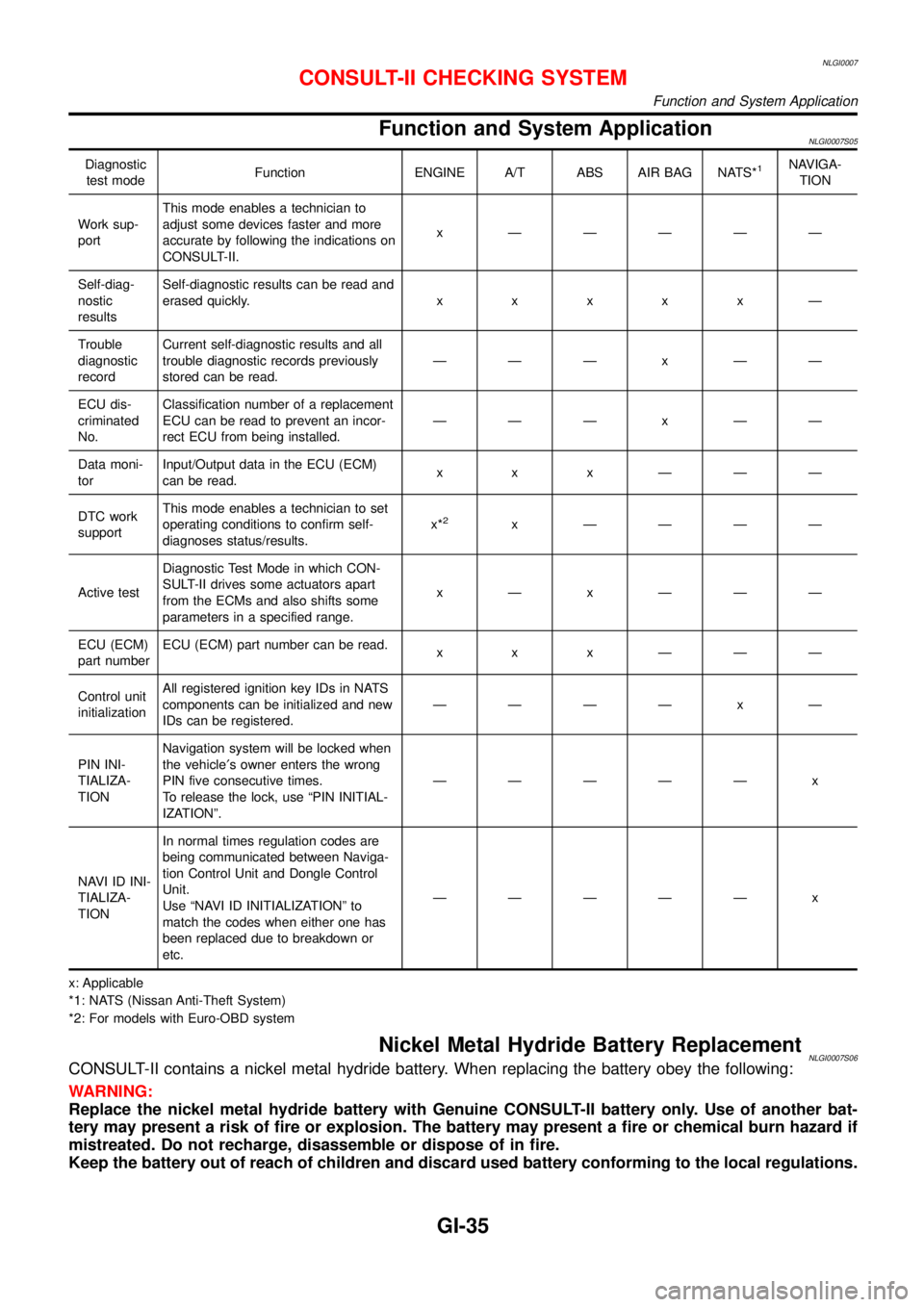
Function and System ApplicationNLGI0007S05
Diagnostic
test modeFunction ENGINE A/T ABS AIR BAG NATS*1NAVIGA-
TION
Work sup-
portThis mode enables a technician to
adjust some devices faster and more
accurate by following the indications on
CONSULT-II.x—————
Self-diag-
nostic
resultsSelf-diagnostic results can be read and
erased quickly.xxxxx—
Trouble
diagnostic
recordCurrent self-diagnostic results and all
trouble diagnostic records previously
stored can be read.———x——
ECU dis-
criminated
No.Classification number of a replacement
ECU can be read to prevent an incor-
rect ECU from being installed.———x——
Data moni-
torInput/Output data in the ECU (ECM)
can be read.xxx———
DTC work
supportThis mode enables a technician to set
operating conditions to confirm self-
diagnoses status/results.x*
2x————
Active testDiagnostic Test Mode in which CON-
SULT-II drives some actuators apart
from the ECMs and also shifts some
parameters in a specified range.x—x———
ECU (ECM)
part numberECU (ECM) part number can be read.
xxx———
Control unit
initializationAll registered ignition key IDs in NATS
components can be initialized and new
IDs can be registered.————x—
PIN INI-
TIALIZA-
TIONNavigation system will be locked when
the vehicle′s owner enters the wrong
PIN five consecutive times.
To release the lock, use“PIN INITIAL-
IZATION”.—————x
NAVI ID INI-
TIALIZA-
TIONIn normal times regulation codes are
being communicated between Naviga-
tion Control Unit and Dongle Control
Unit.
Use“NAVI ID INITIALIZATION”to
match the codes when either one has
been replaced due to breakdown or
etc.—————x
x: Applicable
*1: NATS (Nissan Anti-Theft System)
*2: For models with Euro-OBD system
Nickel Metal Hydride Battery ReplacementNLGI0007S06CONSULT-II contains a nickel metal hydride battery. When replacing the battery obey the following:
WARNING:
Replace the nickel metal hydride battery with Genuine CONSULT-II battery only. Use of another bat-
tery may present a risk of fire or explosion. The battery may present a fire or chemical burn hazard if
mistreated. Do not recharge, disassemble or dispose of in fire.
Keep the battery out of reach of children and discard used battery conforming to the local regulations.
CONSULT-II CHECKING SYSTEM
Function and System Application
GI-35
Page 2700 of 3051

Headlamp .................................................. EL-69
Headlining - See Roof trim ........................ BT-35
Heated oxygen sensor (HO2S)
(front) . EC-184, 192, 198, 204, 214, 414, 709,
717, 723, 729, 739, 944
Heated oxygen sensor (HO2S) heater
(front) .......................... EC-221, 421, 746, 951
Heated oxygen sensor (HO2S) heater
(rear) ........................... EC-263, 433, 786, 963
Heated oxygen sensor (rear) . EC-227, 237, 246,
256, 426, 752, 761, 770, 779, 956
Heated seat ............................................. EL-234
Height (Dimensions) ................................... GI-41
Hood ............................................................ BT-7
Horn ......................................................... EL-193
How to erase DTC for OBD system .. EC-69, 71,
594, 596, 1096
I
IACV-AAC valve ............. EC-343, 466, 863, 995
IATS - Wiring diagram .... EC-163, 409, 689, 939
IGN/SG - Wiring diagram ................ EC-501, 903
ILL - Wiring diagram ................................ EL-109
INJECT - Wiring diagram .............. EC-495, 1022
IVC - Wiring diagram ...................... EC-362, 476
Identification plate ...................................... GI-39
Idle air control (IAC) system .......... EC-343, 466,
863, 995
Idle air control valve (IACV) ........... EC-343, 466,
863, 995
Idle speed ........................................ EC-46,1111
Ignition coil .................................... EC-907, 1010
Ignition control system ............................ EC-500
Ignition timing ............................................ EC-46
Ignition wire inspection ........................... EC-814
Illumination ............................................... EL-107
Injection nozzle ..................................... EC-1083
Injector removal and installation ....... EC-44, 578
Input shaft (FF M/T) ..................... MT-34, 63, 68
Instrument panel ........................................ BT-22
Intake air temperature sensor ........ EC-161, 407,
687, 937
Intake valve timing control solenoid
valve ............................................ EC-360, 475
Interior lamp on-off control ....................... EL-117
Interior lamp ............................................. EL-116
Interior ........................................................ BT-28
J
Jacking points ............................................ GI-43
Joint connector (J/C) ............................... EL-531
Junction box (J/B) .................................... EL-527
K
KS - Wiring diagram ............................... EC-292
Keyless entry system - See Multi-re-
mote control system ............................. EL-314
Knock sensor (KS) ................. EC-291, 815, 816
Knuckle spindle ........................................... AX-5
L
LOAD - Wiring diagram ................ EC-536, 1051
Length (Dimensions) .................................. GI-41
License lamp ............................................. EL-87
Lifting points ............................................... GI-44
Line pressure test (A/T) ............................. AT-52
Liquid gasket application .............. EM-5, 76, 158
Location of electrical units ....................... EL-442
Lock, door .................................................. BT-18
Lubricant (R134a) A/C .............................. HA-87
Lubricants ................................................. MA-20
Lubrication circuit (engine) .............. LC-4, 24, 43
M
M/T major overhaul ............................. MT-24, 62
M/T removal and installation ..................... MT-18
MAFS - Wiring diagram ........ EC-156, 682, 1143
MAIN - Wiring diagram ......... EC-146, 671, 1136
MIL & Data link connectors circuit ......... EC-545,
1060
MIL/DL - Wiring diagram .... EC-545, 1060, 1303
MIRROR - Wiring diagram ...................... EL-241
Magnet clutch ............................................ HA-90
Mainshaft (M/T) ............................ MT-39, 63, 73
Malfunction indicator lamp (MIL) .............. EC-73,
598, 1097
Manual air conditioner - Wiring
diagram .................................................. HA-27
Manual transaxle number .......................... GI-40
Mass air flow sensor (MAFS) ................ EC-154,
679, 1143
Master cylinder (clutch) ............................. CL-11
Meter ........................................................ EL-130
Mirror defogger ........................................ EL-198
Mirror, door ................................................ BT-63
Misfire ............................................. EC-285, 808
Mode door control linkage
adjustment ............................................. HA-48
Model variation ........................................... GI-37
Molding - See Exterior ............................... BT-38
Multi-remote control system .................... EL-314
Multiport fuel injection (MFI) system . EC-35, 569
Multiport fuel injection precautions ............... GI-6
ALPHABETICAL INDEX
IDX-5