Page 353 of 2898
SAT992C
Control Valve Assembly and AccumulatorsNJAT0110REMOVALNJAT0110S011. Drain ATF from transaxle.
2. Remove oil pan and gasket.
SAT064K
3. Disconnect A/T solenoid valve harness connector.
AAT265A
4. Remove stopper ring from A/T solenoid harness terminal body.
5. Remove A/T solenoid harness by pushing terminal body into
transmission case.
AAT260A
6. Remove control valve assembly by removing fixing bolts.
Bolt length, number and location:
Bolt symbol A B C
Bolt length ª!º
40.0 mm
(1.575 in)33.0 mm
(1.299 in)43.5 mm
(1.713 in)
Number of bolts 5 6 2
+Be careful not to drop manual valve and servo release
accumulator return springs.
7. Disassemble and inspect control valve assembly if necessary.
Refer to AT-366.
ON-VEHICLE SERVICE
Control Valve Assembly and Accumulators
AT-351
Page 355 of 2898

SAT480J
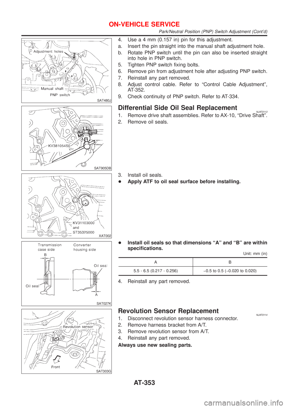
4. Usea4mm(0.157 in) pin for this adjustment.
a. Insert the pin straight into the manual shaft adjustment hole.
b. Rotate PNP switch until the pin can also be inserted straight
into hole in PNP switch.
5. Tighten PNP switch fixing bolts.
6. Remove pin from adjustment hole after adjusting PNP switch.
7. Reinstall any part removed.
8. Adjust control cable. Refer to ªControl Cable Adjustmentº,
AT-352.
9. Check continuity of PNP switch. Refer to AT-334.
SAT905DB
Differential Side Oil Seal ReplacementNJAT01131. Remove drive shaft assemblies. Refer to AX-10, ªDrive Shaftº.
2. Remove oil seals.
XAT002
3. Install oil seals.
+Apply ATF to oil seal surface before installing.
SAT027K
+Install oil seals so that dimensions ªAº and ªBº are within
specifications.
Unit: mm (in)
AB
5.5 - 6.5 (0.217 - 0.256) þ0.5 to 0.5 (þ0.020 to 0.020)
4. Reinstall any part removed.
SAT303G
Revolution Sensor ReplacementNJAT01141. Disconnect revolution sensor harness connector.
2. Remove harness bracket from A/T.
3. Remove revolution sensor from A/T.
4. Reinstall any part removed.
Always use new sealing parts.
ON-VEHICLE SERVICE
Park/Neutral Position (PNP) Switch Adjustment (Cont'd)
AT-353
Page 356 of 2898

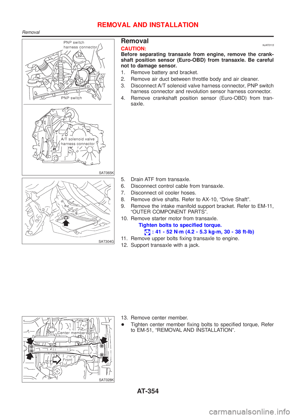
SAT065K
RemovalNJAT0115CAUTION:
Before separating transaxle from engine, remove the crank-
shaft position sensor (Euro-OBD) from transaxle. Be careful
not to damage sensor.
1. Remove battery and bracket.
2. Remove air duct between throttle body and air cleaner.
3. Disconnect A/T solenoid valve harness connector, PNP switch
harness connector and revolution sensor harness connector.
4. Remove crankshaft position sensor (Euro-OBD) from tran-
saxle.
SAT304G
5. Drain ATF from transaxle.
6. Disconnect control cable from transaxle.
7. Disconnect oil cooler hoses.
8. Remove drive shafts. Refer to AX-10, ªDrive Shaftº.
9. Remove the intake manifold support bracket. Refer to EM-11,
ªOUTER COMPONENT PARTSº.
10. Remove starter motor from transaxle.
Tighten bolts to specified torque.
: 41 - 52 N´m (4.2 - 5.3 kg-m, 30 - 38 ft-lb)
11. Remove upper bolts fixing transaxle to engine.
12. Support transaxle with a jack.
SAT028K
13. Remove center member.
+Tighten center member fixing bolts to specified torque, Refer
to EM-51, ªREMOVAL AND INSTALLATIONº.
REMOVAL AND INSTALLATION
Removal
AT-354
Page 365 of 2898
Oil ChannelNJAT0118
SAT032K
OVERHAUL
Oil Channel
AT-363
Page 368 of 2898
NJAT0120
SAT049K
1. Drain ATF through drain plug.
SAT008D
2. Remove torque converter.
SAT009D
3. Check torque converter one-way clutch using check tool as
shown at left.
a. Insert check tool into the groove of bearing support built into
one-way clutch outer race.
b. While fixing bearing support with check tool, rotate one-way
clutch spline using flat-bladed screwdriver.
c. Check inner race rotates clockwise only. If not, replace torque
converter assembly.
SAT586H
4. Remove oil charging pipe and oil cooler tube.
DISASSEMBLY
AT-366
Page 369 of 2898
SAT023JB
5. Set manual shaft to ªPº position.
6. Remove PNP switch.
SAT128E
7. Remove oil pan and oil pan gasket.
+Do not reuse oil pan bolts.
8. Check foreign materials in oil pan to help determine cause of
malfunction. If the fluid is very dark, smells burned, or contains
foreign particles, the frictional material (clutches, band) may
need replacement. A tacky film that will not wipe clean indi-
cates varnish build up. Varnish can cause valves, servo, and
clutches to stick and may inhibit pump pressure.
+If frictional material is detected, replace radiator after
repair of A/T. Refer to LC-16, section ªRadiatorº.
9. Remove control valve assembly according to the following pro-
cedures.
AAT260A
a. Remove control valve assembly mounting bolts A, B and C.
DISASSEMBLY
AT-367
Page 371 of 2898
SAT023DA
16. Check accumulator pistons and contact surface of transmis-
sion case for damage.
17. Check accumulator return springs for damage and free length.
Return springs:
Refer to SDS, AT-484.
SAT129E
18. Remove lip seals from band servo oil port.
SAT027D
19. Remove converter housing according to the following proce-
dures.
a. Remove converter housing mounting bolts A and B.
SAT028D
b. Remove converter housing.
SAT131E
c. Remove O-ring from differential oil port.
DISASSEMBLY
AT-369
Page 372 of 2898
SAT030D
20. Remove final drive assembly from transmission case.
NAT033
21. Remove differential side bearing outer race from transmission
case.
SAT132E
22. Remove differential side bearing adjusting shim from transmis-
sion case.
SAT840DB
23. Remove differential side bearing outer race from converter
housing.
SAT133E
24. Remove oil seal from converter housing using a screwdriver.
+Be careful not to damage case.
DISASSEMBLY
AT-370