Page 1202 of 2898
Diagnostic ProcedureNJEC1255
1 INSPECTION START
Do you have CONSULT-II?
YesorNo
Ye s©GO TO 2.
No©GO TO 3.
2 CHECK OVERALL FUNCTION
With CONSULT-II
1. Start engine and let it idle.
2. Select ªSWIRL CONT SOL/Vº in ªACTIVE TESTº mode with CONSULT-II.
3. Touch ªONº and ªOFFº on CONSULT-II screen.
4. Make sure that the swirl control valve opens and closes by observing the lever movement.
SEF242Z
OK or NG
OK©INSPECTION END
NG©GO TO 4.
SWIRL CONTROL VALVE CONTROL SYSTEM (WHERE FITTED)QG
Diagnostic Procedure
EC-478
Page 1203 of 2898
3 CHECK OVERALL FUNCTION
Without CONSULT-II
1. Disconnect engine coolant temperature sensor harness connector.
2. Connect a resistor (1.5 - 2.0 kW) between terminals of engine coolant temperature sensor harness connector.
SEF982UB
3. Start engine and let it idle.
4. In idle with the swirl control valve set to CLOSE, verify by observing the lever movement that the valve changes to
OPEN when the engine rpm exceeds 2,400 rpm.
SEF242Z
OK or NG
OK©INSPECTION END
NG©Remove resistor. GO TO 4.
SWIRL CONTROL VALVE CONTROL SYSTEM (WHERE FITTED)QG
Diagnostic Procedure (Cont'd)
EC-479
Page 1204 of 2898
4 CHECK VACUUM EXISTENCE
With CONSULT-II
1. Reconnect the disconnected harness connectors.
2. Start engine and let it idle.
3. Remove vacuum hose connected to swirl control valve actuator.
4. Select ªSWIRL CONT SOL/Vº in ªACTIVE TESTº mode with CONSULT-II.
5. Touch ªONº and ªOFFº on CONSULT-II screen.
6. Check vacuum existence and operation delay time under the following conditions.
SEF243Z
Without CONSULT-II
1. Reconnect ECM harness connector.
2. Remove vacuum hose connected to swirl control valve actuator.
3. Start engine and let it idle.
4. Apply 12V of direct current between swirl control valve control solenoid valve terminals 1 and 2.
5. Check vacuum existence and operation delay time under the following conditions.
SEF244Z
OK or NG
OK©GO TO 9.
NG©GO TO 5.
SWIRL CONTROL VALVE CONTROL SYSTEM (WHERE FITTED)QG
Diagnostic Procedure (Cont'd)
EC-480
Page 1208 of 2898

SEF058X
JEF835Z
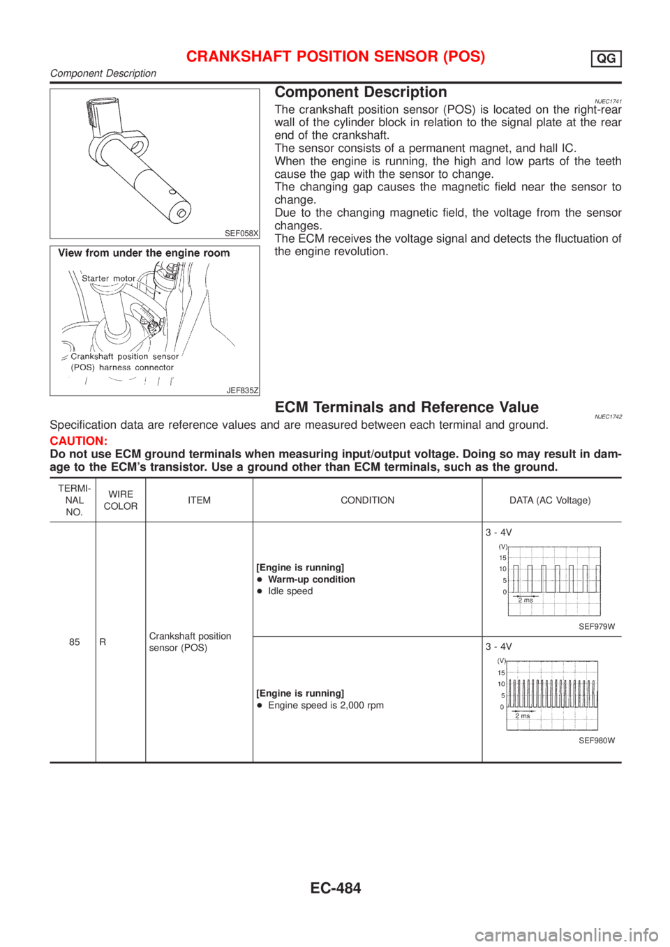
Component DescriptionNJEC1741The crankshaft position sensor (POS) is located on the right-rear
wall of the cylinder block in relation to the signal plate at the rear
end of the crankshaft.
The sensor consists of a permanent magnet, and hall IC.
When the engine is running, the high and low parts of the teeth
cause the gap with the sensor to change.
The changing gap causes the magnetic field near the sensor to
change.
Due to the changing magnetic field, the voltage from the sensor
changes.
The ECM receives the voltage signal and detects the fluctuation of
the engine revolution.
ECM Terminals and Reference ValueNJEC1742Specification data are reference values and are measured between each terminal and ground.
CAUTION:
Do not use ECM ground terminals when measuring input/output voltage. Doing so may result in dam-
age to the ECM's transistor. Use a ground other than ECM terminals, such as the ground.
TERMI-
NAL
NO.WIRE
COLORITEM CONDITION DATA (AC Voltage)
85 RCrankshaft position
sensor (POS)[Engine is running]
+Warm-up condition
+Idle speed3-4V
SEF979W
[Engine is running]
+Engine speed is 2,000 rpm3-4V
SEF980W
CRANKSHAFT POSITION SENSOR (POS)QG
Component Description
EC-484
Page 1209 of 2898
Wiring DiagramNJEC1743SEDAN MODELS AND HATCHBACK MODELS WITH ECM IN ENGINE COMPARTMENTNJEC1743S01
NEF331A
CRANKSHAFT POSITION SENSOR (POS)QG
Wiring Diagram
EC-485
Page 1211 of 2898
Diagnostic ProcedureNJEC1744
1 CHECK OVERALL FUNCTION
1. Start engine and let it idle.
2. Check voltage between ECM terminal 85 and ground.
SEF761Z
OK or NG
OK©INSPECTION END
NG©GO TO 2.
2 RETIGHTEN GROUND SCREWS
1. Turn ignition switch ªOFFº.
2. Loosen and retighten engine ground screws.
JEF104Y
©GO TO 3.
CRANKSHAFT POSITION SENSOR (POS)QG
Diagnostic Procedure
EC-487
Page 1213 of 2898

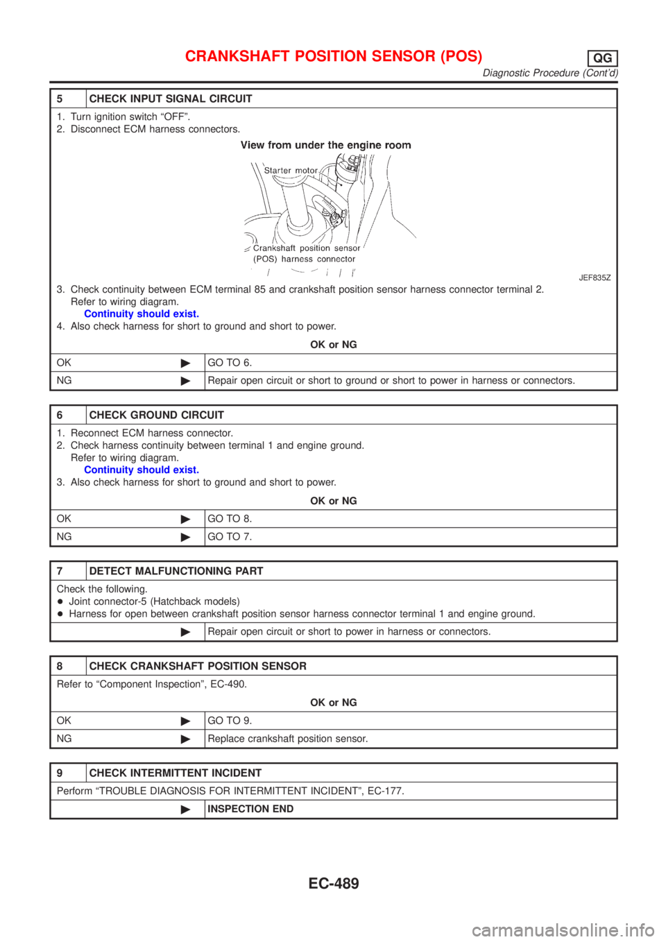
5 CHECK INPUT SIGNAL CIRCUIT
1. Turn ignition switch ªOFFº.
2. Disconnect ECM harness connectors.
JEF835Z
3. Check continuity between ECM terminal 85 and crankshaft position sensor harness connector terminal 2.
Refer to wiring diagram.
Continuity should exist.
4. Also check harness for short to ground and short to power.
OK or NG
OK©GO TO 6.
NG©Repair open circuit or short to ground or short to power in harness or connectors.
6 CHECK GROUND CIRCUIT
1. Reconnect ECM harness connector.
2. Check harness continuity between terminal 1 and engine ground.
Refer to wiring diagram.
Continuity should exist.
3. Also check harness for short to ground and short to power.
OK or NG
OK©GO TO 8.
NG©GO TO 7.
7 DETECT MALFUNCTIONING PART
Check the following.
+Joint connector-5 (Hatchback models)
+Harness for open between crankshaft position sensor harness connector terminal 1 and engine ground.
©Repair open circuit or short to power in harness or connectors.
8 CHECK CRANKSHAFT POSITION SENSOR
Refer to ªComponent Inspectionº, EC-490.
OK or NG
OK©GO TO 9.
NG©Replace crankshaft position sensor.
9 CHECK INTERMITTENT INCIDENT
Perform ªTROUBLE DIAGNOSIS FOR INTERMITTENT INCIDENTº, EC-177.
©INSPECTION END
CRANKSHAFT POSITION SENSOR (POS)QG
Diagnostic Procedure (Cont'd)
EC-489
Page 1215 of 2898

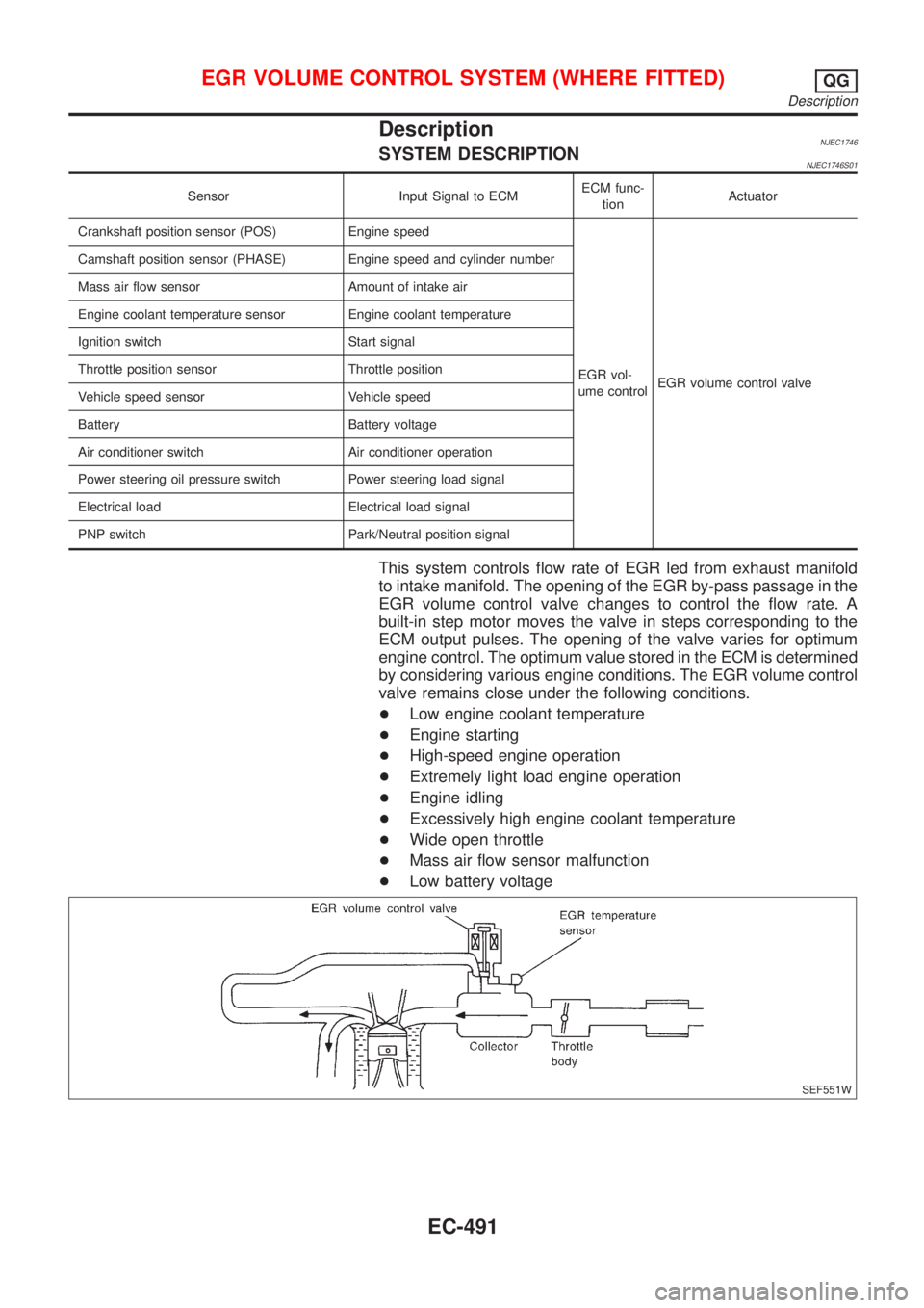
DescriptionNJEC1746SYSTEM DESCRIPTIONNJEC1746S01
Sensor Input Signal to ECMECM func-
tionActuator
Crankshaft position sensor (POS) Engine speed
EGR vol-
ume controlEGR volume control valve Camshaft position sensor (PHASE) Engine speed and cylinder number
Mass air flow sensor Amount of intake air
Engine coolant temperature sensor Engine coolant temperature
Ignition switch Start signal
Throttle position sensor Throttle position
Vehicle speed sensor Vehicle speed
Battery Battery voltage
Air conditioner switch Air conditioner operation
Power steering oil pressure switch Power steering load signal
Electrical load Electrical load signal
PNP switch Park/Neutral position signal
This system controls flow rate of EGR led from exhaust manifold
to intake manifold. The opening of the EGR by-pass passage in the
EGR volume control valve changes to control the flow rate. A
built-in step motor moves the valve in steps corresponding to the
ECM output pulses. The opening of the valve varies for optimum
engine control. The optimum value stored in the ECM is determined
by considering various engine conditions. The EGR volume control
valve remains close under the following conditions.
+Low engine coolant temperature
+Engine starting
+High-speed engine operation
+Extremely light load engine operation
+Engine idling
+Excessively high engine coolant temperature
+Wide open throttle
+Mass air flow sensor malfunction
+Low battery voltage
SEF551W
EGR VOLUME CONTROL SYSTEM (WHERE FITTED)QG
Description
EC-491