Page 1377 of 2898
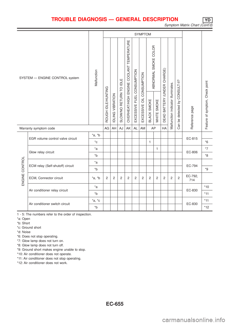
SYSTEM Ð ENGINE CONTROL system
Malfunction
SYMPTOM
Reference page
Feature of symptom, Check pointROUGH IDLE/HUNTING
IDLING VIBRATION
SLOW/NO RETURN TO IDLE
OVERHEAT/HIGH ENGINE COOLANT TEMPERATURE
EXCESSIVE FUEL CONSUMPTION
EXCESSIVE OIL CONSUMPTION
ABNORMAL SMOKE COLOR
DEAD BATTERY (UNDER CHARGE)
Malfunction indicator illuminates.
Can be detected by CONSULT-II?BLACK SMOKE
WHITE SMOKEWarranty symptom code AG AH AJ AK AL AM AP HA
ENGINE CONTROL
Start signal circuit *a, *b EC-823 *3
Accelerator position switch (Idle) circuit*a, *c
EC-685
*b 1 1 *4
Ignition switch circuit*a
EC-666
*b*5
Power supply for ECM circuit*a
1 1 EC-666
*b
1 - 5: The numbers refer to the order of inspection.
(continued on next page)
*a: Open
*b: Short
*c: Ground short
*d: Noise
*3: Start control does not function.
*4: Accelerator position sensor NG signal is output.
*5: Engine does not stop.
TROUBLE DIAGNOSIS Ð GENERAL DESCRIPTIONYD
Symptom Matrix Chart (Cont'd)
EC-653
Page 1379 of 2898

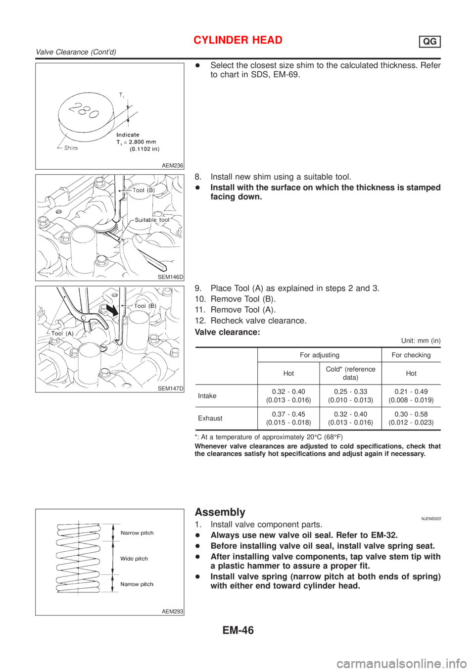
SYSTEM Ð ENGINE CONTROL system
Malfunction
SYMPTOM
Reference page
Feature of symptom, Check pointROUGH IDLE/HUNTING
IDLING VIBRATION
SLOW/NO RETURN TO IDLE
OVERHEAT/HIGH ENGINE COOLANT TEMPERATURE
EXCESSIVE FUEL CONSUMPTION
EXCESSIVE OIL CONSUMPTION
ABNORMAL SMOKE COLOR
DEAD BATTERY (UNDER CHARGE)
Malfunction indicator illuminates.
Can be detected by CONSULT-II?BLACK SMOKE
WHITE SMOKEWarranty symptom code AG AH AJ AK AL AM AP HA
ENGINE CONTROL
EGR volume control valve circuit*a, *b
EC-815
*c 1 *6
Glow relay circuit*a 1
EC-806*7
*b*8
ECM relay (Self-shutoff) circuit*a
EC-794
*b*9
ECM, Connector circuit *a, *b22222222222EC-792,
714
Air conditioner relay circuit*a
EC-830*10
*b*11
Air conditioner switch circuit*a, *c
EC-830*11
*b*12
1 - 5: The numbers refer to the order of inspection.
*a: Open
*b: Short
*c: Ground short
*d: Noise
*6: Does not stop operating.
*7: Glow lamp does not turn on.
*8: Glow lamp does not turn off.
*9: Ground short makes engine unable to stop.
*10: Air conditioner does not operate.
*11: Air conditioner does not stop operating.
*12: Air conditioner does not work.
TROUBLE DIAGNOSIS Ð GENERAL DESCRIPTIONYD
Symptom Matrix Chart (Cont'd)
EC-655
Page 1455 of 2898
![NISSAN ALMERA 2001 Service Manual TERMI-
NAL
NO.WIRE
COLORITEM CONDITION DATA(DC Voltage)
221 LG/B Cooling fan relay (High)[Engine is running]
+Cooling fans are not operating
+Cooling fans are operating at low speedBATTERY VOLTAGE
(11 NISSAN ALMERA 2001 Service Manual TERMI-
NAL
NO.WIRE
COLORITEM CONDITION DATA(DC Voltage)
221 LG/B Cooling fan relay (High)[Engine is running]
+Cooling fans are not operating
+Cooling fans are operating at low speedBATTERY VOLTAGE
(11](/manual-img/5/57348/w960_57348-1454.png)
TERMI-
NAL
NO.WIRE
COLORITEM CONDITION DATA(DC Voltage)
221 LG/B Cooling fan relay (High)[Engine is running]
+Cooling fans are not operating
+Cooling fans are operating at low speedBATTERY VOLTAGE
(11 - 14V)
[Engine is running]
+Cooling fans are operating at high speedApproximately 0.1V
On Board Diagnosis LogicNJEC0663This diagnosis continuously monitors the engine coolant temperature.
If the cooling fan or another component in the cooling system malfunctions, engine coolant temperature will
rise.
When the engine coolant temperature reaches an abnormally high temperature condition, a malfunction is
indicated.
DTC Malfunction is detected when ... Check Items (Possible Cause)
P1217
0208+Cooling fan does not operate properly (Overheat).
+Cooling fan system does not operate properly
(Overheat).
+Engine coolant was not added to the system using
the proper filling method.+Harness or connectors
(The cooling fan circuit is open or shorted.)
+Cooling fan
+Radiator hose
+Radiator
+Radiator cap
+Water pump
+Thermostat
+Engine coolant temperature sensor
For more information, refer to ªMAIN 12 CAUSES OF
OVERHEATINGº, EC-756.
CAUTION:
When a malfunction is indicated, be sure to replace the coolant following the procedure in the LC-44,
ªChanging Engine Coolantº. Also, replace the engine oil.
1) Fill radiator with coolant up to specified level with a filling speed of 2 liters per minute. Be sure
to use coolant with the proper mixture ratio. Refer to MA-18, ªEngine Coolant Mixture Ratioº.
2) After refilling coolant, run engine to ensure that no water-flow noise is emitted.
DTC P1217 OVER HEATYD
ECM Terminals and Reference Value (Cont'd)
EC-731
Page 2145 of 2898
Removal and InstallationNJEM0006
YEM008
1. Oil pressure switch
2. EGR valve*
3. EGR tube*
4. Air relief plug
5. Intake manifold6. Intake manifold upper support
7. Intake manifold rear supports
8. Oil filter
9. Thermostat
10. Water pump11. Water pump pulley
12. EGR solenoid valve*
13. EGR guide tube*
14. EGR gas temperature sensor*
*: If so equipped
OUTER COMPONENT PARTSQG
Removal and Installation
EM-11
Page 2148 of 2898
YEM011
1. Crankshaft pulley
2. Engine coolant temperature
3. Gasket
4. Exhaust manifold
5. Exhaust manifold cover6. Thermal transmitter
7. Water drain plug
8. Heated oxygen sensor 1 (front)
9. Three way catalyst10. Converter cap
11. Converter cover
12. Ignition coil
13. Spark plug
OUTER COMPONENT PARTSQG
Removal and Installation (Cont'd)
EM-14
Page 2180 of 2898

AEM236
+Select the closest size shim to the calculated thickness. Refer
to chart in SDS, EM-69.
SEM146D
8. Install new shim using a suitable tool.
+Install with the surface on which the thickness is stamped
facing down.
SEM147D
9. Place Tool (A) as explained in steps 2 and 3.
10. Remove Tool (B).
11. Remove Tool (A).
12. Recheck valve clearance.
Valve clearance:
Unit: mm (in)
For adjusting For checking
HotCold* (reference
data)Hot
Intake0.32 - 0.40
(0.013 - 0.016)0.25 - 0.33
(0.010 - 0.013)0.21 - 0.49
(0.008 - 0.019)
Exhaust0.37 - 0.45
(0.015 - 0.018)0.32 - 0.40
(0.013 - 0.016)0.30 - 0.58
(0.012 - 0.023)
*: At a temperature of approximately 20ÉC (68ÉF)
Whenever valve clearances are adjusted to cold specifications, check that
the clearances satisfy hot specifications and adjust again if necessary.
AEM293
AssemblyNJEM00201. Install valve component parts.
+Always use new valve oil seal. Refer to EM-32.
+Before installing valve oil seal, install valve spring seat.
+After installing valve components, tap valve stem tip with
a plastic hammer to assure a proper fit.
+Install valve spring (narrow pitch at both ends of spring)
with either end toward cylinder head.
CYLINDER HEADQG
Valve Clearance (Cont'd)
EM-46
Page 2189 of 2898

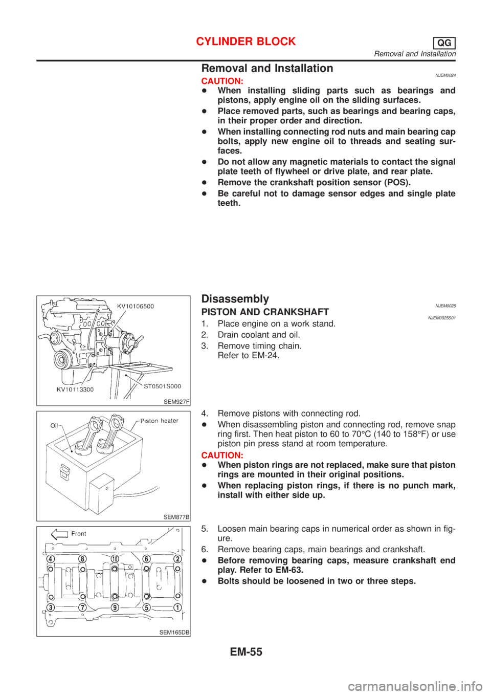
Removal and InstallationNJEM0024CAUTION:
+When installing sliding parts such as bearings and
pistons, apply engine oil on the sliding surfaces.
+Place removed parts, such as bearings and bearing caps,
in their proper order and direction.
+When installing connecting rod nuts and main bearing cap
bolts, apply new engine oil to threads and seating sur-
faces.
+Do not allow any magnetic materials to contact the signal
plate teeth of flywheel or drive plate, and rear plate.
+Remove the crankshaft position sensor (POS).
+Be careful not to damage sensor edges and single plate
teeth.
SEM927F
DisassemblyNJEM0025PISTON AND CRANKSHAFTNJEM0025S011. Place engine on a work stand.
2. Drain coolant and oil.
3. Remove timing chain.
Refer to EM-24.
SEM877B
4. Remove pistons with connecting rod.
+When disassembling piston and connecting rod, remove snap
ring first. Then heat piston to 60 to 70ÉC (140 to 158ÉF) or use
piston pin press stand at room temperature.
CAUTION:
+When piston rings are not replaced, make sure that piston
rings are mounted in their original positions.
+When replacing piston rings, if there is no punch mark,
install with either side up.
SEM165DB
5. Loosen main bearing caps in numerical order as shown in fig-
ure.
6. Remove bearing caps, main bearings and crankshaft.
+Before removing bearing caps, measure crankshaft end
play. Refer to EM-63.
+Bolts should be loosened in two or three steps.
CYLINDER BLOCKQG
Removal and Installation
EM-55
Page 2302 of 2898

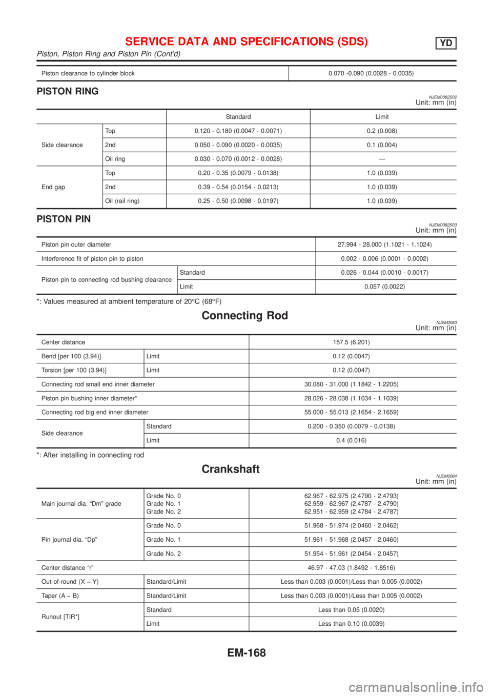
Piston clearance to cylinder block 0.070 -0.090 (0.0028 - 0.0035)
PISTON RINGNJEM0082S02Unit: mm (in)
Standard Limit
Side clearanceTop 0.120 - 0.180 (0.0047 - 0.0071) 0.2 (0.008)
2nd 0.050 - 0.090 (0.0020 - 0.0035) 0.1 (0.004)
Oil ring 0.030 - 0.070 (0.0012 - 0.0028) Ð
End gapTop 0.20 - 0.35 (0.0079 - 0.0138) 1.0 (0.039)
2nd 0.39 - 0.54 (0.0154 - 0.0213) 1.0 (0.039)
Oil (rail ring) 0.25 - 0.50 (0.0098 - 0.0197) 1.0 (0.039)
PISTON PINNJEM0082S03Unit: mm (in)
Piston pin outer diameter27.994 - 28.000 (1.1021 - 1.1024)
Interference fit of piston pin to piston 0.002 - 0.006 (0.0001 - 0.0002)
Piston pin to connecting rod bushing clearanceStandard 0.026 - 0.044 (0.0010 - 0.0017)
Limit 0.057 (0.0022)
*: Values measured at ambient temperature of 20ÉC (68ÉF)
Connecting RodNJEM0083Unit: mm (in)
Center distance157.5 (6.201)
Bend [per 100 (3.94)] Limit 0.12 (0.0047)
Torsion [per 100 (3.94)] Limit 0.12 (0.0047)
Connecting rod small end inner diameter 30.080 - 31.000 (1.1842 - 1.2205)
Piston pin bushing inner diameter* 28.026 - 28.038 (1.1034 - 1.1039)
Connecting rod big end inner diameter 55.000 - 55.013 (2.1654 - 2.1659)
Side clearanceStandard 0.200 - 0.350 (0.0079 - 0.0138)
Limit 0.4 (0.016)
*: After installing in connecting rod
CrankshaftNJEM0084Unit: mm (in)
Main journal dia. ªDmº gradeGrade No. 0
Grade No. 1
Grade No. 262.967 - 62.975 (2.4790 - 2.4793)
62.959 - 62.967 (2.4787 - 2.4790)
62.951 - 62.959 (2.4784 - 2.4787)
Pin journal dia. ªDpºGrade No. 0 51.968 - 51.974 (2.0460 - 2.0462)
Grade No. 1 51.961 - 51.968 (2.0457 - 2.0460)
Grade No. 2 51.954 - 51.961 (2.0454 - 2.0457)
Center distance ªrº46.97 - 47.03 (1.8492 - 1.8516)
Out-of-round (X þ Y) Standard/Limit Less than 0.003 (0.0001)/Less than 0.005 (0.0002)
Taper (A þ B) Standard/Limit Less than 0.003 (0.0001)/Less than 0.005 (0.0002)
Runout [TIR*]Standard Less than 0.05 (0.0020)
Limit Less than 0.10 (0.0039)
SERVICE DATA AND SPECIFICATIONS (SDS)YD
Piston, Piston Ring and Piston Pin (Cont'd)
EM-168