2001 NISSAN ALMERA engine
[x] Cancel search: enginePage 797 of 2898
Only one set of freeze frame data (either 1st trip freeze frame data or freeze frame data) can be stored in the
ECM. 1st trip freeze frame data is stored in the ECM memory along with the 1st trip DTC. There is no prior-
ity for 1st trip freeze frame data and it is updated each time a different 1st trip DTC is detected. However, once
freeze frame data is stored in the ECM memory, 1st trip freeze frame data is no longer stored. Remember,
only one set of freeze frame data can be stored in the ECM.
If freeze frame data is stored in the ECM memory and another freeze frame data occurs later, the first (origi-
nal) freeze frame data remains unchanged in the ECM memory.
Both 1st trip freeze frame data and freeze frame data (along with the DTCs) are cleared when the ECM
memory is erased. Procedures for clearing the ECM memory are described in ªHow to Erase Emission-related
Diagnostic Informationº, EC-73.
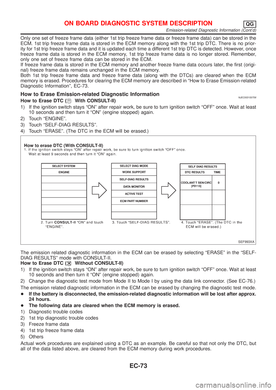
How to Erase Emission-related Diagnostic InformationNJEC0031S0706How to Erase DTC (With CONSULT-II)
1) If the ignition switch stays ªONº after repair work, be sure to turn ignition switch ªOFFº once. Wait at least
10 seconds and then turn it ªONº (engine stopped) again.
2) Touch ªENGINEº.
3) Touch ªSELF-DIAG RESULTSº.
4) Touch ªERASEº. (The DTC in the ECM will be erased.)
SEF993XA
The emission related diagnostic information in the ECM can be erased by selecting ªERASEº in the ªSELF-
DIAG RESULTSº mode with CONSULT-II.
How to Erase DTC (
Without CONSULT-II)
1) If the ignition switch stays ªONº after repair work, be sure to turn ignition switch ªOFFº once. Wait at least
10 seconds and then turn it ªONº (engine stopped) again.
2) Change the diagnostic test mode from Mode II to Mode I by using the data link connector. (See EC-76.)
The emission related diagnostic information in the ECM can be erased by changing the diagnostic test mode.
+If the battery is disconnected, the emission-related diagnostic information will be lost after approx.
24 hours.
+The following data are cleared when the ECM memory is erased.
1) Diagnostic trouble codes
2) 1st trip diagnostic trouble codes
3) Freeze frame data
4) 1st trip freeze frame data
5) Others
Actual work procedures are explained using a DTC as an example. Be careful so that not only the DTC, but
all of the data listed above, are cleared from the ECM memory during work procedures.
ON BOARD DIAGNOSTIC SYSTEM DESCRIPTIONQG
Emission-related Diagnostic Information (Cont'd)
EC-73
Page 798 of 2898
SEF543X
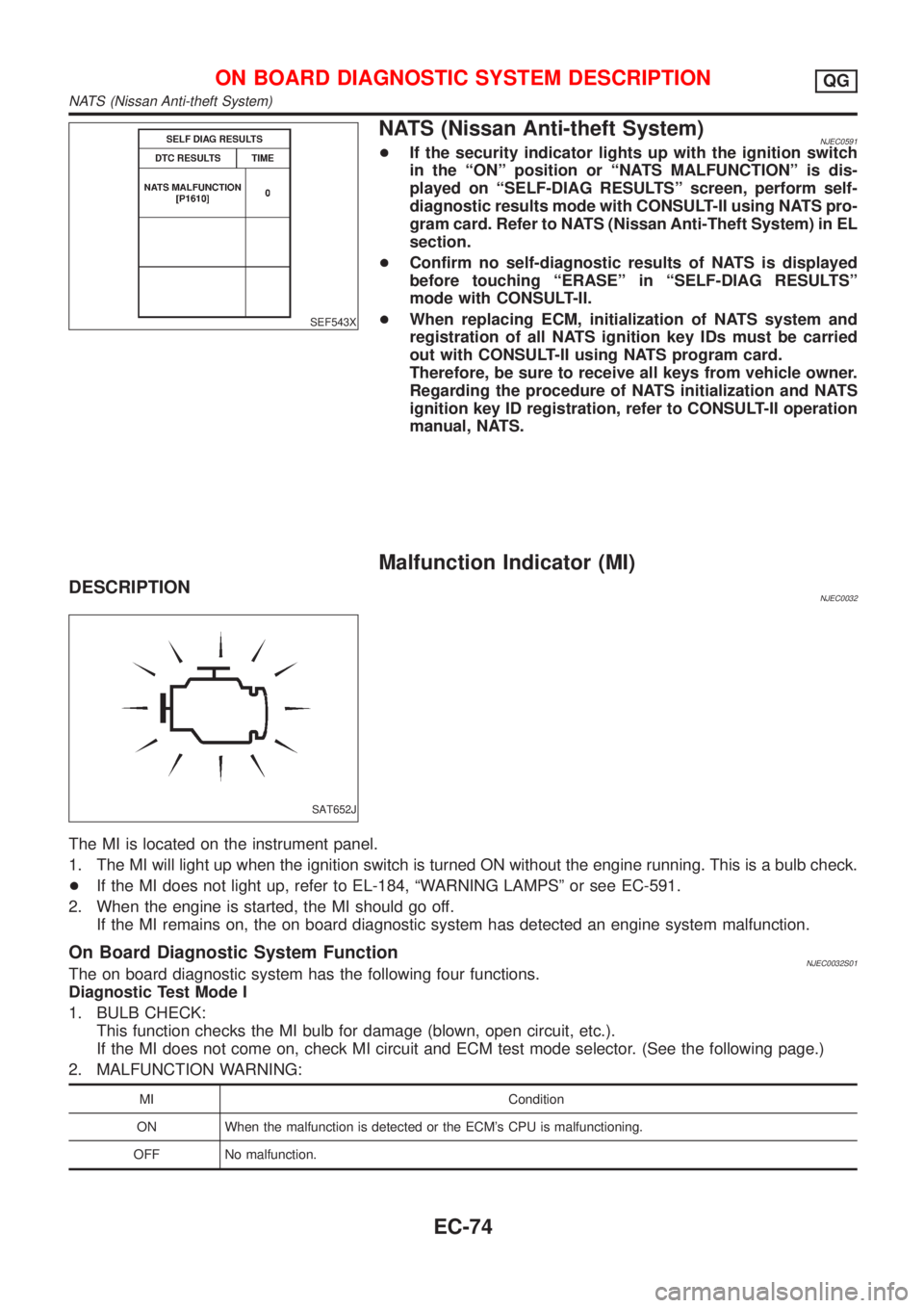
NATS (Nissan Anti-theft System)NJEC0591+If the security indicator lights up with the ignition switch
in the ªONº position or ªNATS MALFUNCTIONº is dis-
played on ªSELF-DIAG RESULTSº screen, perform self-
diagnostic results mode with CONSULT-II using NATS pro-
gram card. Refer to NATS (Nissan Anti-Theft System) in EL
section.
+Confirm no self-diagnostic results of NATS is displayed
before touching ªERASEº in ªSELF-DIAG RESULTSº
mode with CONSULT-II.
+When replacing ECM, initialization of NATS system and
registration of all NATS ignition key IDs must be carried
out with CONSULT-II using NATS program card.
Therefore, be sure to receive all keys from vehicle owner.
Regarding the procedure of NATS initialization and NATS
ignition key ID registration, refer to CONSULT-II operation
manual, NATS.
Malfunction Indicator (MI)
DESCRIPTIONNJEC0032
SAT652J
The MI is located on the instrument panel.
1. The MI will light up when the ignition switch is turned ON without the engine running. This is a bulb check.
+If the MI does not light up, refer to EL-184, ªWARNING LAMPSº or see EC-591.
2. When the engine is started, the MI should go off.
If the MI remains on, the on board diagnostic system has detected an engine system malfunction.
On Board Diagnostic System FunctionNJEC0032S01The on board diagnostic system has the following four functions.
Diagnostic Test Mode I
1. BULB CHECK:
This function checks the MI bulb for damage (blown, open circuit, etc.).
If the MI does not come on, check MI circuit and ECM test mode selector. (See the following page.)
2. MALFUNCTION WARNING:
MI Condition
ON When the malfunction is detected or the ECM's CPU is malfunctioning.
OFF No malfunction.
ON BOARD DIAGNOSTIC SYSTEM DESCRIPTIONQG
NATS (Nissan Anti-theft System)
EC-74
Page 799 of 2898
Diagnostic Test Mode II (If so equipped)
3. SELF-DIAGNOSTIC RESULTS:
This function allows DTCs and 1st trip DTCs to be read.
4. HEATED OXYGEN SENSOR 1 MONITOR (FRONT):
This function allows the fuel mixture condition (lean or rich), monitored by heated oxygen sensor 1 (front),
to be read.
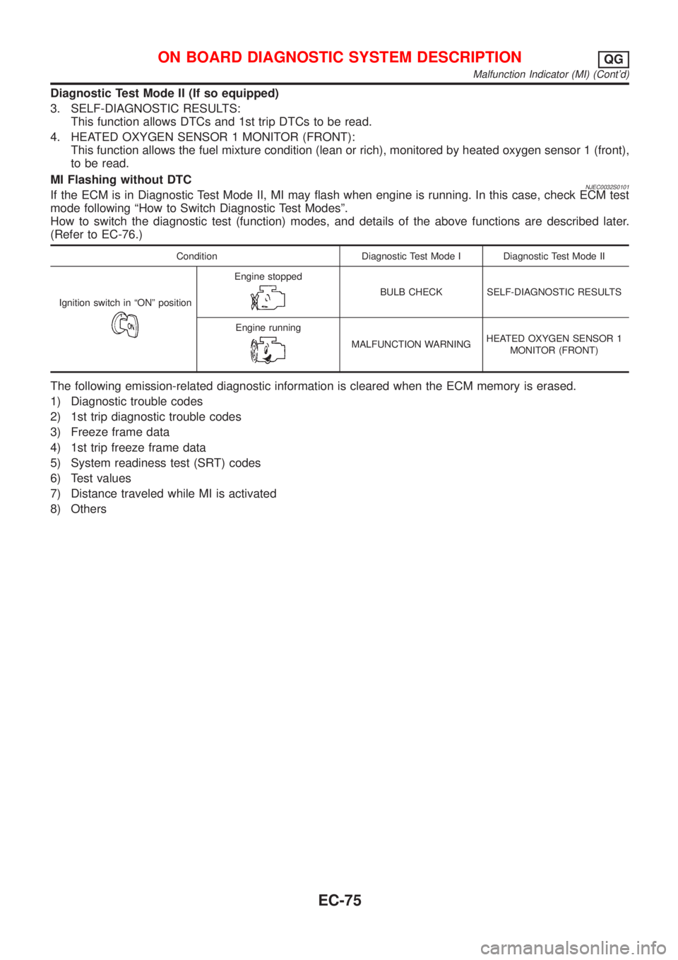
MI Flashing without DTC
NJEC0032S0101If the ECM is in Diagnostic Test Mode II, MI may flash when engine is running. In this case, check ECM test
mode following ªHow to Switch Diagnostic Test Modesº.
How to switch the diagnostic test (function) modes, and details of the above functions are described later.
(Refer to EC-76.)
Condition Diagnostic Test Mode I Diagnostic Test Mode II
Ignition switch in ªONº position
Engine stopped
BULB CHECK SELF-DIAGNOSTIC RESULTS
Engine running
MALFUNCTION WARNINGHEATED OXYGEN SENSOR 1
MONITOR (FRONT)
The following emission-related diagnostic information is cleared when the ECM memory is erased.
1) Diagnostic trouble codes
2) 1st trip diagnostic trouble codes
3) Freeze frame data
4) 1st trip freeze frame data
5) System readiness test (SRT) codes
6) Test values
7) Distance traveled while MI is activated
8) Others
ON BOARD DIAGNOSTIC SYSTEM DESCRIPTIONQG
Malfunction Indicator (MI) (Cont'd)
EC-75
Page 802 of 2898

MI Fuel mixture condition in the exhaust gas Air fuel ratio feedback control condition
ON Lean
Closed loop system
OFF Rich
*Remains ON or OFF Any condition Open loop system
*: Maintains conditions just before switching to open loop.
To check the heated oxygen sensor 1 (front) function, start engine in the Diagnostic Test Mode II and warm
it up until engine coolant temperature indicator points to the middle of the gauge.
Next run engine at about 2,000 rpm for about 2 minutes under no-load conditions. Then make sure that the
MI comes ON more than 5 times within 10 seconds with engine running at 2,000 rpm under no-load.
OBD System Operation Chart (With Euro-OBD
Models Only)
NJEC0033RELATIONSHIP BETWEEN MI, 1ST TRIP DTC, DTC, AND DETECTABLE ITEMSNJEC0033S01+When a malfunction is detected for the first time, the 1st trip DTC and the 1st trip freeze frame data are
stored in the ECM memory.
+When the same malfunction is detected in two consecutive trips, the DTC and the freeze frame data are
stored in the ECM memory, and the MI will come on. For details, refer to ªTwo Trip Detection Logicº on
EC-59.
+The MI will go off after the vehicle is driven 3 times with no malfunction. The drive is counted only when
the recorded driving pattern is met (as stored in the ECM). If another malfunction occurs while counting,
the counter will reset.
+The DTC and the freeze frame data will be stored until the vehicle is driven 40 times (driving pattern A)
without the same malfunction recurring (except for Misfire and Fuel Injection System). For Misfire and Fuel
Injection System, the DTC and freeze frame data will be stored until the vehicle is driven 80 times (driv-
ing pattern C) without the same malfunction recurring. The ªTIMEº in ªSELF-DIAGNOSTIC RESULTSº
mode of CONSULT-II will count the number of times the vehicle is driven.
+The 1st trip DTC is not displayed when the self-diagnosis results in ªOKº for the 2nd trip.
SUMMARY CHARTNJEC0033S02
Items Fuel Injection System Misfire Other
MI (goes off) 3 (pattern B) 3 (pattern B) 3 (pattern B)
DTC, Freeze Frame Data (no display) 80 (pattern C) 80 (pattern C) 40 (pattern A)
1st Trip DTC (clear) 1 (pattern C), *1 1 (pattern C), *1 1 (pattern B)
1st Trip Freeze Frame Data (clear) *1, *2 *1, *2 1 (pattern B)
For details about patterns ªBº and ªCº under ªFuel Injection Systemº and ªMisfireº, see EC-80.
For details about patterns ªAº and ªBº under ªOtherº, see EC-82.
*1: Clear timing is at the moment OK is detected.
*2: Clear timing is when the same malfunction is detected in the 2nd trip.
ON BOARD DIAGNOSTIC SYSTEM DESCRIPTIONQG
Malfunction Indicator (MI) (Cont'd)
EC-78
Page 804 of 2898
EXPLANATION FOR DRIVING PATTERNS FOR ªMISFIRE
NJEC0033S04Driving Pattern BNJEC0033S0401Driving pattern B means the vehicle operation as follows:
All components and systems should be monitored at least once by the OBD system.
+The B counter will be cleared when the malfunction is detected once regardless of the driving pattern.
+The B counter will be counted up when driving pattern B is satisfied without any malfunction.
+The MI will go off when the B counter reaches 3. (*2 in EC-79)
Driving Pattern CNJEC0033S0402Driving pattern C means the vehicle operation as follows:
1) The following conditions should be satisfied at the same time:
Engine speed: (Engine speed in the freeze frame data)±375 rpm
Calculated load value: (Calculated load value in the freeze frame data)´(1±0.1) [%]
Engine coolant temperature (T) condition:
+When the freeze frame data shows lower than 70ÉC (158ÉF), ªTº should be lower than 70ÉC (158ÉF).
+When the freeze frame data shows higher than or equal to 70ÉC (158ÉF), ªTº should be higher than or
equal to 70ÉC (158ÉF).
Example:
If the stored freeze frame data is as follows:
Engine speed: 850 rpm, Calculated load value: 30%, Engine coolant temperature: 80ÉC (176ÉF)
To be satisfied with driving pattern C, the vehicle should run under the following conditions:
Engine speed: 475 - 1,225 rpm, Calculated load value: 27 - 33%, Engine coolant temperature: more than 70ÉC
(158ÉF)
+The C counter will be cleared when the malfunction is detected regardless of driving pattern C.
+The C counter will be counted up when driving pattern C is satisfied without the same malfunction.
+The DTC will not be displayed after C counter reaches 80.
+The 1st trip DTC will be cleared when C counter is counted once without the same malfunction after DTC
is stored in ECM.
ON BOARD DIAGNOSTIC SYSTEM DESCRIPTIONQG
OBD System Operation Chart (With Euro-OBD Models Only) (Cont'd)
EC-80
Page 807 of 2898
SEF094Y
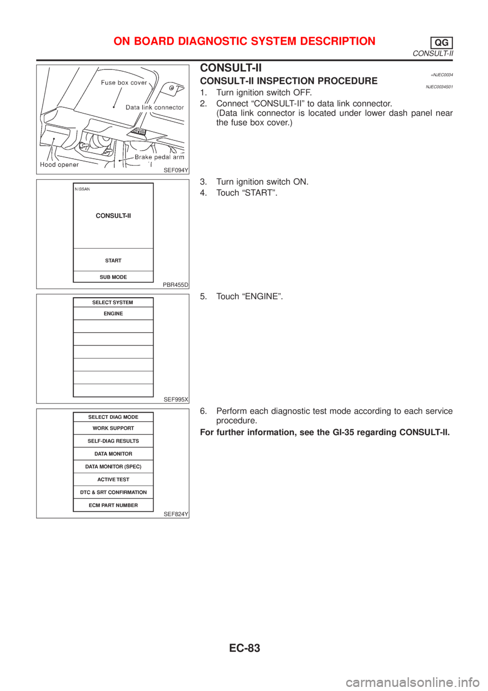
CONSULT-II=NJEC0034CONSULT-II INSPECTION PROCEDURENJEC0034S011. Turn ignition switch OFF.
2. Connect ªCONSULT-IIº to data link connector.
(Data link connector is located under lower dash panel near
the fuse box cover.)
PBR455D
3. Turn ignition switch ON.
4. Touch ªSTARTº.
SEF995X
5. Touch ªENGINEº.
SEF824Y
6. Perform each diagnostic test mode according to each service
procedure.
For further information, see the GI-35 regarding CONSULT-II.
ON BOARD DIAGNOSTIC SYSTEM DESCRIPTIONQG
CONSULT-II
EC-83
Page 808 of 2898

ENGINE CONTROL COMPONENT PARTS/CONTROL
SYSTEMS APPLICATION
NJEC0034S02
ItemDIAGNOSTIC TEST MODE
WORK
SUP-
PORTSELF-DIAGNOSTIC
RESULTS
D ATA
MONI-
TORD ATA
MONI-
TOR
(SPEC)ACTIVE
TESTDTC & SRT
CONFIRMATION
DTC*1FREEZE
FRAME
DATA*2SRT
STA-
TUSDTC
WORK
SUP-
PORT
ENGINE CONTROL COMPONENT PARTS
INPUTCamshaft position sensor
(PHASE)XEngine
speed
XEngine
speed
XEngine
speed
X
Crankshaft position sensor
(POS)X*3
Mass air flow sensor X X X
Engine coolant temperature
sensorXXXXX
Heated oxygen sensor 1
(front)X X X X*3 X*3
Heated oxygen sensor 2
(rear)X*3 X X X*3 X*3
Vehicle speed sensorXXXX
Throttle position sensor X X X
Fuel tank temperature sensor X X
EGR temperature sensor*4 X*3 X X
Intake air temperature sensor X*3 X X X
Knock sensor X
Ignition switch (start signal) X X
Closed throttle position
switch*4X*3 X X
Closed throttle position switch
(throttle position sensor sig-
nal)XX
Air conditioner switch X X
Refrigerant pressure sensor X X
Park/Neutral position (PNP)
switchX*3 X X
Power steering oil pressure
switchXX
Electrical load X X
Heater fan switch X X
Battery voltage X X
ON BOARD DIAGNOSTIC SYSTEM DESCRIPTIONQG
CONSULT-II (Cont'd)
EC-84
Page 809 of 2898

ItemDIAGNOSTIC TEST MODE
WORK
SUP-
PORTSELF-DIAGNOSTIC
RESULTS
D ATA
MONI-
TORD ATA
MONI-
TOR
(SPEC)ACTIVE
TESTDTC & SRT
CONFIRMATION
DTC*1FREEZE
FRAME
DATA*2SRT
STA-
TUSDTC
WORK
SUP-
PORT
ENGINE CONTROL COMPONENT PARTS
OUT-
PUTInjectors X X X
Power transistor (Ignition tim-
ing)X*3
(misfire)XXX
IACV-AAC valve X X*3 X X X
Intake valve timing control
solenoid valveXXX
EVAP canister purge volume
control solenoid valveX*3 X X X
Air conditioner relay X X
Fuel pump relay X X X X
EGR volume control valve*4 X*3 X X X X*3
Heated oxygen sensor 1
heater (front)X*3 X X X*3
Heated oxygen sensor 2
heater (rear)X*3 X X X*3
Cooling fan X X X
Swirl control valve control
solenoid valve*4X*3 X X X
Calculated load value X X X
X: Applicable
*1: This item includes 1st trip DTCs.
*2: This mode includes 1st trip freeze frame data or freeze frame data. The items appear on CONSULT-II screen in freeze frame data
mode only if a 1st trip DTC or DTC is detected. For details, refer to EC-61, EC-72.
*3: Not applicable for models without Euro-OBD system
*4: If so equipped
FUNCTIONNJEC0034S03
Diagnostic test mode Function
Work supportThis mode enables a technician to adjust some devices faster and more accurately by following the
indications on the CONSULT-II unit.
Self-diagnostic resultsSelf-diagnostic results such as 1st trip DTC, DTCs and 1st trip freeze frame data or freeze frame
data can be read and erased quickly.*1
Data monitor Input/Output data in the ECM can be read.
Data monitor (spec)Input/Output specifications of the basic fuel schedule, AFM, A/F feedback control value and the
other data monitor items can be read.
Active testDiagnostic Test Mode in which CONSULT-II drives some actuators apart from the ECMs and also
shifts some parameters in a specified range.
DTC and SRT confirmation The status of system monitoring tests and the self-diagnosis status/result can be confirmed.
ECM part number ECM part numbers can be read.
*1 The following emission-related diagnostic information is cleared when the ECM memory is erased.
1) Diagnostic trouble codes
ON BOARD DIAGNOSTIC SYSTEM DESCRIPTIONQG
CONSULT-II (Cont'd)
EC-85