2001 NISSAN ALMERA reset
[x] Cancel search: resetPage 1360 of 2898
the ªDTC Confirmation Procedureº, the moment a malfunction
is found the DTC will be displayed. Refer to GI-22, ªIncident
Simulation Testsº.
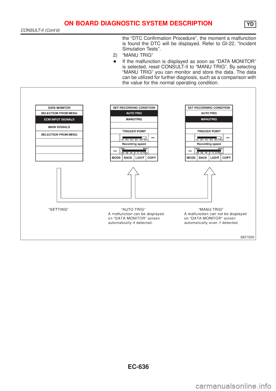
2) ªMANU TRIGº
+If the malfunction is displayed as soon as ªDATA MONITORº
is selected, reset CONSULT-II to ªMANU TRIGº. By selecting
ªMANU TRIGº you can monitor and store the data. The data
can be utilized for further diagnosis, such as a comparison with
the value for the normal operating condition.
SEF720X
ON BOARD DIAGNOSTIC SYSTEM DESCRIPTIONYD
CONSULT-II (Cont'd)
EC-636
Page 1731 of 2898
Combination Meter Self-Diagnosis/HatchbackNJEL0447PERFORMING SELF-DIAGNOSIS MODENJEL0447S011. Turn the ignition switch to the ªLOCKº position.
2. Press both reset buttons on the combination meter and keep
them depressed.
3. Turn the ignition switch to the ªONº position, while keeping the
reset buttons pressed.
4. Release both reset buttons then self-diagnosis will start. The
sequence (A to L) is activated by press the either reset buttons.
NOTE:
If either reset button is not pressed for 20 seconds at each step or
if the ignition switch is turned OFF, the self-diagnosis mode is
exited.
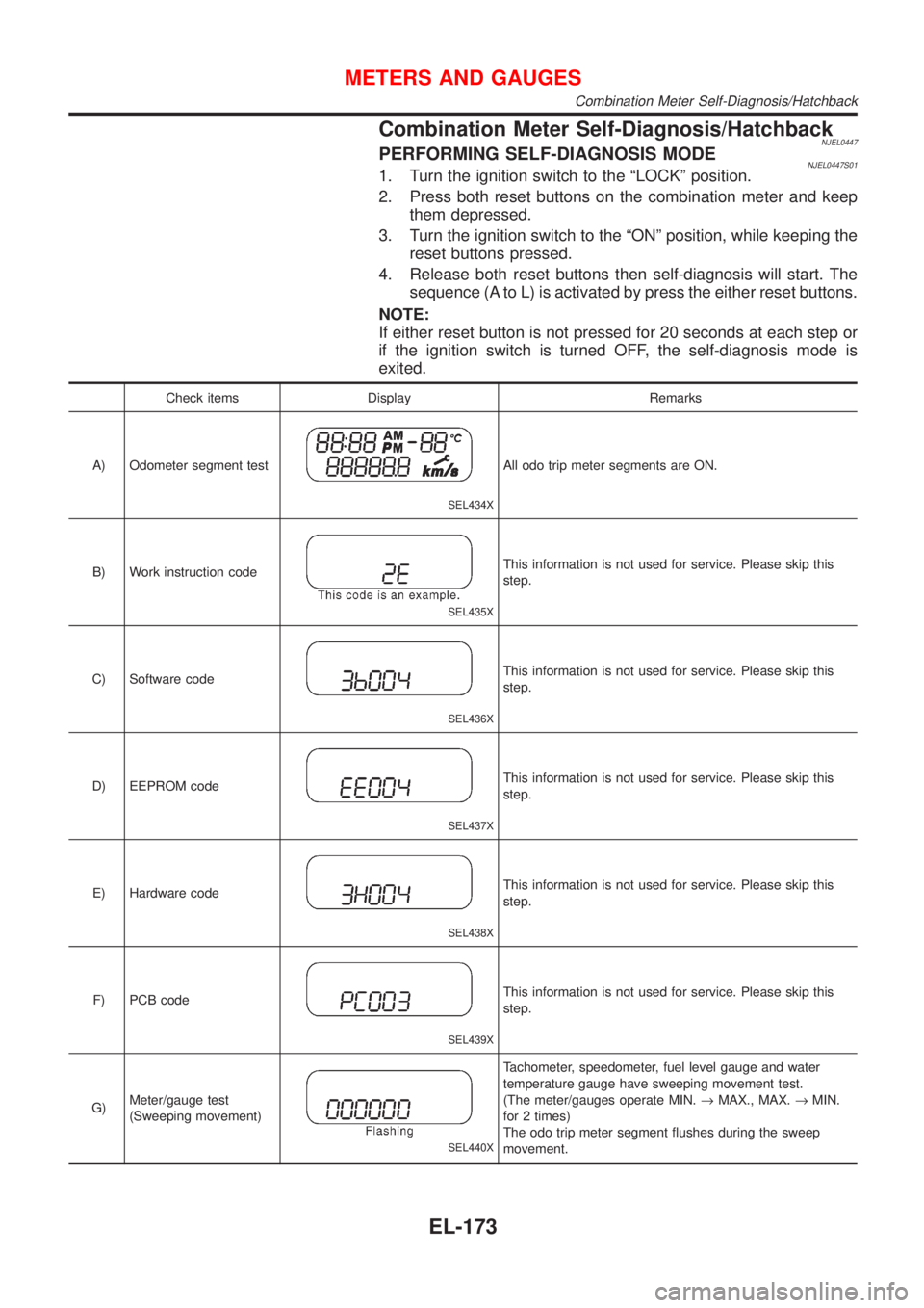
Check items Display Remarks
A) Odometer segment test
SEL434X
All odo trip meter segments are ON.
B) Work instruction code
SEL435X
This information is not used for service. Please skip this
step.
C) Software code
SEL436X
This information is not used for service. Please skip this
step.
D) EEPROM code
SEL437X
This information is not used for service. Please skip this
step.
E) Hardware code
SEL438X
This information is not used for service. Please skip this
step.
F) PCB code
SEL439X
This information is not used for service. Please skip this
step.
G)Meter/gauge test
(Sweeping movement)
SEL440X
Tachometer, speedometer, fuel level gauge and water
temperature gauge have sweeping movement test.
(The meter/gauges operate MIN.®MAX., MAX.®MIN.
for 2 times)
The odo trip meter segment flushes during the sweep
movement.
METERS AND GAUGES
Combination Meter Self-Diagnosis/Hatchback
EL-173
Page 1733 of 2898
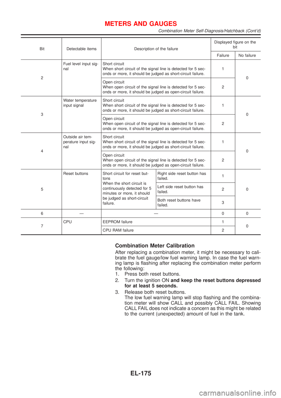
Bit Detectable items Description of the failureDisplayed figure on the
bit
Failure No failure
2Fuel level input sig-
nalShort circuit
When short circuit of the signal line is detected for 5 sec-
onds or more, it should be judged as short-circuit failure.1
0
Open circuit
When open circuit of the signal line is detected for 5 sec-
onds or more, it should be judged as open-circuit failure.2
3Water temperature
input signalShort circuit
When short circuit of the signal line is detected for 5 sec-
onds or more, it should be judged as short-circuit failure.1
0
Open circuit
When open circuit of the signal line is detected for 5 sec-
onds or more, it should be judged as open-circuit failure.2
4Outside air tem-
perature input sig-
nalShort circuit
When short circuit of the signal line is detected for 5 sec-
onds or more, it should be judged as short-circuit failure.1
0
Open circuit
When open circuit of the signal line is detected for 5 sec-
onds or more, it should be judged as open-circuit failure.2
5Reset buttons Short circuit for reset but-
tons
When the short circuit is
continuously detected for 5
minutes or more, it should
be judged as short-circuit
failure.Right side reset button has
failed.1
0 Left side reset button has
failed.2
Both reset buttons have
failed.3
6Ð Ð 00
7CPU EEPROM failure 1
0
CPU RAM failure 2
Combination Meter Calibration
After replacing a combination meter, it might be necessary to cali-
brate the fuel gauge/low fuel warning lamp. In case the fuel warn-
ing lamp is flashing after replacing the combination meter perform
the following:
1. Press both reset buttons.
2. Turn the ignition ONand keep the reset buttons depressed
for at least 5 seconds.
3. Release both reset buttons.
The low fuel warning lamp will stop flashing and the combina-
tion meter will show CALL and possibly CALL FAIL. Showing
CALL FAIL does not indicate a concern as this might be related
to the current (unexpected) amount of fuel in the tank.
METERS AND GAUGES
Combination Meter Self-Diagnosis/Hatchback (Cont'd)
EL-175
Page 1816 of 2898
System Description/Sedan=NJEL0381Refer to Owner's Manual for audio system operating instructions.
Power is supplied at all times
+through 15A fuse (No. 32, located in the fusible link and fuse block)
+to audio unit terminal 9
+to CD auto changer terminal 32.
With the ignition switch in the ACC or ON position, power is supplied
+through 10A fuse [No. 1, located in the fuse block (J/B)]
+to audio unit terminal 3,
+to CD auto changer terminal 36
Ground is supplied through the case of the audio unit.
Audio signals are supplied
+through audio unit terminals 7, 10, 11, 12, 13, 14, 15, 16
+to terminals 1 and 2 of front door speaker LH and RH,
+to terminals 1 and 2 of rear door speaker LH and RH and
+to terminals 1 and 2 of pillar tweeter LH and RH (with 6 speakers)
When the navigation system is triggered,
power is supplied
+through navi control unit terminal 46
+to speaker relay terminal 2
Ground is supplied
+through navi control unit terminal 44
+to speaker relay terminal 1
With power and ground supplied, the relay is energized, and then audio signal is interrupted to front door
speaker RH (LHD models) or LH (RHD models), and pillar tweeter RH (LHD models) or LH (RHD models)
For detailed, refer to ªNAVIGATION SYSTEMº.
NATS AUDIO LINKNJEL0381S04DescriptionNJEL0381S0401The link with the NATS IMMU implies that the audio unit can basically only be operated if connected to the
matching NATS IMMU to which the audio unit was initially fitted on the production line.
Since radio operation is impossible after the link with the NATS is disrupted theft of the audio unit is basically
useless since special equipment is required to reset the audio unit.
Initialization process for audio units that are linked to the NATS IMMU
New audio units will be delivered to the factories in the ªNEWº state, i.e. ready to be linked with the vehicle's
NATS. When the audio unit in ªNEWº state is first switched on at the factory, it will start up communication
with the vehicle's immobiliser control unit (IMMU) and send a code (the ªaudio unit Codeº) to the IMMU. The
IMMU will then store this code, which is unique to each audio unit, in its (permanent) memory.
Upon receipt of the code by the IMMU, the NATS will confirm correct receipt of the audio unit code to the audio
unit. Hereafter, the audio unit will operate as normal.
During the initialisation process, ªNEWº is displayed on the audio unit display. Normally though, communica-
tion between audio unit and IMMU takes such a short time (300 ms) that the audio unit seems to switch on
directly without showing ªNEWº on its display.
Normal operation
Each time the audio unit is switched on afterwards, the audio unit code will be verified between the audio unit
and the NATS before the audio unit becomes operational. During the code verification process, ªWAITº is
shown on the audio unit display. Again, the communication takes such a short time (300 ms) that the audio
unit seems to switch on directly without showing ªWAITº on its display.
When the radio is locked
In case of a audio unit being linked with the vehicle's NATS (immobilizer system), disconnection of the link
between the audio unit and the IMMU will cause the audio unit to switch into the lock (ªSECUREº) mode in
which the audio unit is fully inoperative. Hence, repair of the audio unit is basically impossible, unless the audio
unit is reset to the ªNEWº state for which special decoding equipment is required.
Clarion has provided their authorized service representatives with so called ªdecoder boxesº which can bring
the audio unit back to the ªNEWº state, enabling the audio unit to be switched on after which repair can be
AUDIO
System Description/Sedan
EL-258
Page 1817 of 2898
carried out. Subsequently, when the repaired audio unit is delivered to the final user again, it will be in the
ªNEWº state as to enable re-linking the audio unit to the vehicle's immobiliser system. As a result of the above,
repair of the audio unit can only be done by an authorized Clarion representative.
SPEED DEPENDENT VOLUME CONTROLNJEL0381S06DescriptionNJEL0381S0601If activated, the radio output volume will be automatically adjusted to compensate for increasing driving noises
at higher driving speeds.
The radio receives a speed signal from the vehicle speed sensor (VSS) and selects the output volume.
PERSONAL AUDIO SETTINGSNJEL0381S07DescriptionNJEL0381S0701The radio is designed to store several settings (volume, bass, treble, preset stations and level of speed
dependent volume control) with every NATS ignition key used. Up to a maximum of 4 NATS keys can be reg-
istered. During the communication as mentioned under ªAnti-Theft Systemº, the radio will recognize the used
ignition key and select the accompanying settings.
AUDIO
System Description/Sedan (Cont'd)
EL-259
Page 1827 of 2898
System Description/Hatchback=NJEL0497Refer to Owner's Manual for audio system operating instructions.
Power is supplied at all times
+through 15A fuse (No. 32, located in the fusible link and fuse block)
+to audio unit terminal 9
+to CD auto changer terminal 32.
With the ignition switch in the ACC or ON position, power is supplied
+through 10A fuse [No. 1, located in the fuse block (J/B)]
+to audio unit terminal 3,
+to CD auto changer terminal 36 and
Ground is supplied through the case of the audio unit.
Audio signals are supplied
+through audio unit terminals 7, 10, 11, 12, 13, 14, 15, 16
+to terminals 1 and 2 of front door speaker LH and RH,
+to terminals 1 and 2 of rear door speaker LH and RH and
+to terminals 1 and 2 of pillar tweeter LH and RH (with 6 speakers)
When the navigation system is triggered,
power is supplied
+through navi control unit terminal 46
+to speaker relay terminal 2
Ground is supplied
+through navi control unit terminal 44
+to speaker relay terminal 1
With power and ground supplied, the relay is energized, and then audio signal is interrupted to front door
speaker RH (LHD models) or LH (RHD models), and pillar tweeter RH (LHD models) or LH (RHD models)
For detailed, refer to ªNAVIGATION SYSTEMº.
NATS AUDIO LINKNJEL0497S01DescriptionNJEL0497S0101The link with the NATS IMMU implies that the audio unit can basically only be operated if connected to the
matching NATS IMMU to which the audio unit was initially fitted on the production line.
Since radio operation is impossible after the link with the NATS is disrupted theft of the audio unit is basically
useless since special equipment is required to reset the audio unit.
Initialization process for audio units that are linked to the NATS IMMU
New audio units will be delivered to the factories in the ªNEWº state, i.e. ready to be linked with the vehicle's
NATS. When the audio unit in ªNEWº state is first switched on at the factory, it will start up communication
with the vehicle's immobiliser control unit (IMMU) and send a code (the ªaudio unit Codeº) to the IMMU. The
IMMU will then store this code, which is unique to each audio unit, in its (permanent) memory.
Upon receipt of the code by the IMMU, the NATS will confirm correct receipt of the audio unit code to the audio
unit. Hereafter, the audio unit will operate as normal.
During the initialisation process, ªNEWº is displayed on the audio unit display. Normally though, communica-
tion between audio unit and IMMU takes such a short time (300 ms) that the audio unit seems to switch on
directly without showing ªNEWº on its display.
Normal operation
Each time the audio unit is switched on afterwards, the audio unit code will be verified between the audio unit
and the NATS before the audio unit becomes operational. During the code verification process, ªWAITº is
shown on the audio unit display. Again, the communication takes such a short time (300 ms) that the audio
unit seems to switch on directly without showing ªWAITº on its display.
When the radio is locked
In case of a audio unit being linked with the vehicle's NATS (immobilizer system), disconnection of the link
between the audio unit and the IMMU will cause the audio unit to switch into the lock (ªSECUREº) mode in
which the audio unit is fully inoperative. Hence, repair of the audio unit is basically impossible, unless the audio
unit is reset to the ªNEWº state for which special decoding equipment is required.
Clarion has provided their authorized service representatives with so called ªdecoder boxesº which can bring
the audio unit back to the ªNEWº state, enabling the audio unit to be switched on after which repair can be
AUDIO
System Description/Hatchback
EL-269
Page 1828 of 2898
carried out. Subsequently, when the repaired audio unit is delivered to the final user again, it will be in the
ªNEWº state as to enable re-linking the audio unit to the vehicle's immobiliser system. As a result of the above,
repair of the audio unit can only be done by an authorized Clarion representative.
SPEED DEPENDENT VOLUME CONTROLNJEL0497S02DescriptionNJEL0497S0201If activated, the radio output volume will be automatically adjusted to compensate for increasing driving noises
at higher driving speeds.
The radio receives a speed signal from the vehicle speed sensor (VSS) and selects the output volume.
PERSONAL AUDIO SETTINGSNJEL0497S03DescriptionNJEL0497S0301The radio is designed to store several settings (volume, bass, treble, preset stations and level of speed
dependent volume control) with every NATS ignition key used. Up to a maximum of 4 NATS keys can be reg-
istered. During the communication as mentioned under ªNATS audio linkº, the radio will recognize the used
ignition key and select the accompanying settings.
AUDIO
System Description/Hatchback (Cont'd)
EL-270
Page 1838 of 2898
Trouble DiagnosesNJEL0385AUDIO UNITNJEL0385S05
Symptom Possible causes Repair order
Audio unit inoperative (no
digital display and no
sound from speakers).1. 10A fuse
2. Poor audio unit case ground
3. Audio unit1. Check 10A fuse [No. 1, located in fuse block (J/B)].
Turn ignition switch ON and verify that battery posi-
tive voltage is present at terminal 3 of audio unit.
2. Check audio unit case ground.
3. Remove audio unit for repair.
Audio unit presets are lost
when ignition switch is
turned OFF.1. 15A fuse
2. Audio unit1. Check 15A fuse [No. 32, located in fuse block (J/B)]
and verify that battery positive voltage is present at
terminal 9 of audio unit.
2. Remove audio unit for repair.
Individual rear speaker is
noisy or inoperative.1. Each speaker
2. Output circuit to each speaker1. Check speaker.
2. Check the output circuits to each speaker
+between audio unit and speaker amp.
+between speaker amp. and each speaker.
AM/FM stations are weak
or noisy.1. Roof antenna
2. Audio unit ground
3. Audio unit1. Check roof antenna.
2. Check audio unit ground condition.
3. Remove audio unit for repair.
Audio unit generates noise
in AM and FM modes with
engine running.1. Poor audio unit ground
2. Loose or missing ground bonding straps
3. Ignition condenser or rear window defog-
ger noise suppressor condenser
4. Ignition coil or secondary wiring
5. Audio unit1. Check audio unit ground.
2. Check ground bonding straps.
3. Replace ignition condenser or rear window defogger
noise suppressor condenser.
4. Check ignition coil and secondary wiring.
5. Remove audio unit for repair.
Audio unit generates noise
in AM and FM modes with
accessories on (switch
pops and motor noise).1. Poor audio unit ground
2. Antenna
3. Accessory ground
4. Faulty accessory1. Check audio unit ground.
2. Check antenna.
3. Check accessory ground.
4. Replace accessory.
CD AUTOCHANGERNJEL0385S06Testing Magazines and DiscsNJEL0385S06011. Confirm discs are installed correctly into the magazine (not upside down).
2. Visually inspect/compare the customer's discs with each other and other discs.
Identify any of the following conditions:
+Discs with a large outside diameter. [Normal size is 120 mm (4.72 in).]
+Discs with rough or lipped edges.
+Discs with excessive thickness [Normal size is 1.2 mm (0.047 in).]
+Discs with scratches, abrasions, or pits on the surface.
+Discs with grease/oil, fingerprints, foreign material.
+Discs are warped due to excessive heat exposure.
3. Slide/place the discs in and out of the various magazine positions.
Identify any discs and/or positions that require additional force for placement/ejection. If interference
(sticking, excessive tensions) is found, replace the magazine or the discs.
NOTE:
+Discs which are marginally out of specification (ex. dirty, scratched and so on) may play correctly
on a home stereo.
However, when used in the automotive environment skipping may occur due to the added vehicle
movement and/or vibration due to road conditions. Autochangers should not be replaced when
discs are at fault.
+Use a soft damp cloth to wipe the discs starting from the center outward in radial direction. Never
use chemical cleaning solutions to clean the discs.
AUDIO
Trouble Diagnoses
EL-280