2001 NISSAN ALMERA length
[x] Cancel search: lengthPage 487 of 2898

Band ServoNJAT0196RETURN SPRINGNJAT0196S01Unit: mm (in)
Return spring Free length Outer diameter Part number*
2nd servo return spring 32.5 (1.280) 25.9 (1.020) 31605-31X20
OD servo return spring 38.52 (1.5165) 22.0 (0.866) 31605-31X21
*: Always check with the Parts Department for the latest parts information.
Removal and InstallationNJAT0197Unit: mm (in)
Distance between end of converter housing and torque converter 15.9 (0.626) or more
Shift Solenoid ValvesNJAT0223
Gear Solenoid A Solenoid B
1st ON ON
2nd OFF ON
3rd OFF OFF
4th ON OFF
ResistanceNJAT0224
Solenoid valve Resistance (Approx.) Terminal number
Shift solenoid A 20 - 30W2
Shift solenoid B 5 - 20W1
Ovr. clutch sol. 20 - 30W3
Line pres. sol. 2.5 - 5W4
T/conv. clutch sol. 5 - 20W5
ATF Temp. SensorNJAT0225
Temperature Resistance
20ÉC (68ÉF)
¯
80ÉC (176ÉF)Approximately 1.5V
¯
Approximatley 0.5VApproximately 2.5 kW
¯
Approximately 0.3 kW
Revolution SensorNJAT0226
Condition Judgement standard
When moving at 20 km/h (12 MPH), use the CONSULT-II pulse frequency measuring
function.*1
CAUTION:
Connect the diagnosis data link cable to the vehicle diagnosis connector.
*1: A circuit tester cannot be used to test this item.Approximately 150 Hz
When vehicle parks.Under 1.3V or over 4.5V
Dropping ResistorNJAT0227
Resistance 10 - 15W
SERVICE DATA AND SPECIFICATIONS (SDS)
Band Servo
AT-485
Page 504 of 2898
Support BearingNJAX0018S05Make sure wheel bearing rolls freely and is free from noise, cracks,
pitting or wear.
Support Bearing BracketNJAX0018S06Check support bearing bracket for cracks with a magnetic explora-
tion or dyeing test.
ASSEMBLYNJAX0019+After drive shaft has been assembled, ensure that it
moves smoothly over its entire range without binding.
+Use NISSAN GENUINE GREASE or equivalent after every
overhaul.
SFA800
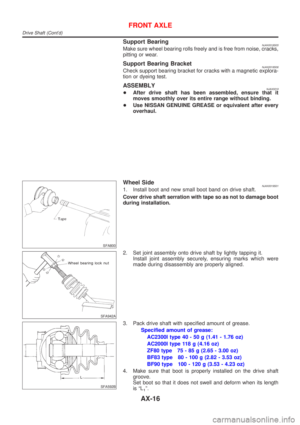
Wheel SideNJAX0019S011. Install boot and new small boot band on drive shaft.
Cover drive shaft serration with tape so as not to damage boot
during installation.
SFA942A
2. Set joint assembly onto drive shaft by lightly tapping it.
Install joint assembly securely, ensuring marks which were
made during disassembly are properly aligned.
SFA592B
3. Pack drive shaft with specified amount of grease.
Specified amount of grease:
AC2300I type 40 - 50 g (1.41 - 1.76 oz)
AC2000I type 118 g (4.16 oz)
ZF80 type 75 - 85 g (2.65 - 3.00 oz)
BF83 type 80 - 100 g (2.82 - 3.53 oz)
BF90 type 100 - 120 g (3.53 - 4.23 oz)
4. Make sure that boot is properly installed on the drive shaft
groove.
Set boot so that it does not swell and deform when its length
is ªL
1º.
FRONT AXLE
Drive Shaft (Cont'd)
AX-16
Page 505 of 2898
Length ªL1º:
AC2300I type 94 - 96 mm (3.70 - 3.78 in)
AC2000I type 90 mm (3.54 in)
ZF80 type 91.4 - 91.6 mm (3.598 - 3.606 in)
BF83 type 95 mm (3.74 in)
BF90 type 85.5 mm (3.366 in)
SFA443B
5. Lock new larger and smaller boot bands securely with a suit-
able tool.
SFA313B
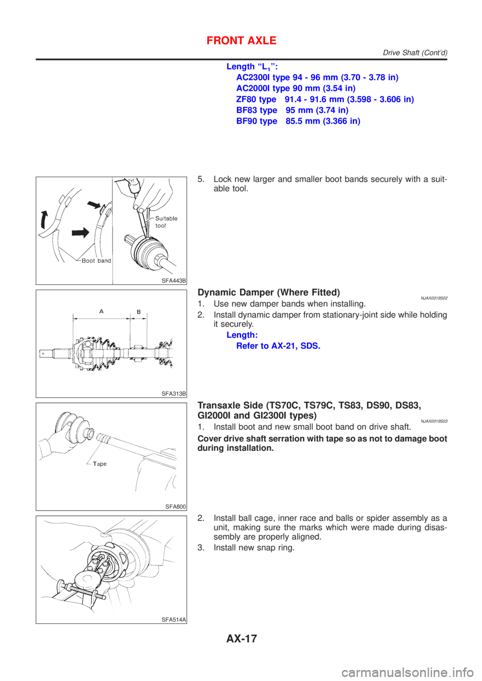
Dynamic Damper (Where Fitted)NJAX0019S021. Use new damper bands when installing.
2. Install dynamic damper from stationary-joint side while holding
it securely.
Length:
Refer to AX-21, SDS.
SFA800
Transaxle Side (TS70C, TS79C, TS83, DS90, DS83,
GI2000I and GI2300I types)
NJAX0019S031. Install boot and new small boot band on drive shaft.
Cover drive shaft serration with tape so as not to damage boot
during installation.
SFA514A
2. Install ball cage, inner race and balls or spider assembly as a
unit, making sure the marks which were made during disas-
sembly are properly aligned.
3. Install new snap ring.
FRONT AXLE
Drive Shaft (Cont'd)
AX-17
Page 506 of 2898
SFA149A
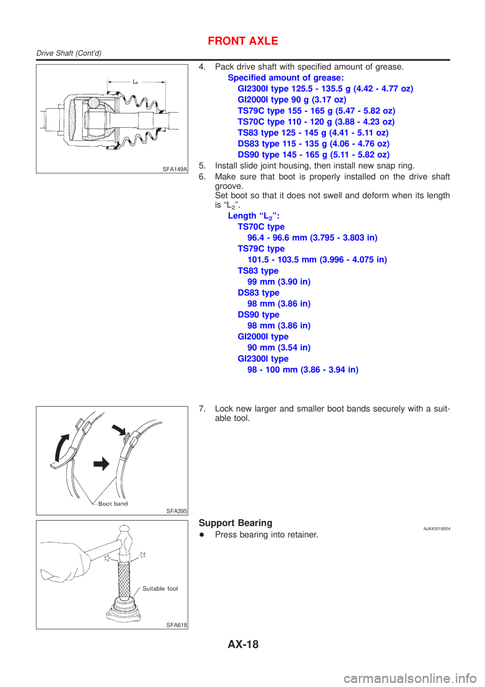
4. Pack drive shaft with specified amount of grease.
Specified amount of grease:
GI2300I type 125.5 - 135.5 g (4.42 - 4.77 oz)
GI2000I type 90 g (3.17 oz)
TS79C type 155 - 165 g (5.47 - 5.82 oz)
TS70C type 110 - 120 g (3.88 - 4.23 oz)
TS83 type 125 - 145 g (4.41 - 5.11 oz)
DS83 type 115 - 135 g (4.06 - 4.76 oz)
DS90 type 145 - 165 g (5.11 - 5.82 oz)
5. Install slide joint housing, then install new snap ring.
6. Make sure that boot is properly installed on the drive shaft
groove.
Set boot so that it does not swell and deform when its length
is ªL
2º.
Length ªL
2º:
TS70C type
96.4 - 96.6 mm (3.795 - 3.803 in)
TS79C type
101.5 - 103.5 mm (3.996 - 4.075 in)
TS83 type
99 mm (3.90 in)
DS83 type
98 mm (3.86 in)
DS90 type
98 mm (3.86 in)
GI2000I type
90 mm (3.54 in)
GI2300I type
98 - 100 mm (3.86 - 3.94 in)
SFA395
7. Lock new larger and smaller boot bands securely with a suit-
able tool.
SFA618
Support BearingNJAX0019S04+Press bearing into retainer.
FRONT AXLE
Drive Shaft (Cont'd)
AX-18
Page 508 of 2898

Service Data and Specifications (SDS)
DRIVE SHAFT=NJAX0020
Applied modelEngine QG15DE QG18DE YD22T
Body Hatchback Sedan All All
Transaxle M/T All M/T
Joint typeTransaxle side GI2000I TS70C TS79C GI2300I DS90 + B
Wheel side AC2000I ZF80 ZF90 AC2300I BF90
Grease Quality Nissan genuine grease or equivalent*2
Capacity
g (oz)Transaxle side 90 (3.17)110 - 120
(3.88 - 4.23)155 - 165
(5.47 - 5.82)125.5 - 135.5
(4.42 - 4.77)145 - 165
(5.11 - 5.82)
Wheel side 118 (4.16)71-81
(2.50 - 2.86)Ð*340-50
(1.41 - 1.76)100 - 120
(3.53 - 4.23)
Boot length
mm (in)Transaxle side ªL
2º 90 (3.54)*195.5 - 97.5
(3.760 - 3.839)101.5 - 103.5
(3.996 - 4.075)98 - 100
(3.86 - 3.94)*197-99
(3.82 - 3.90)
Wheel side ªL
1º 90 (3.54)*190.5 - 92.5
(3.563 - 3.642)Ð*394-96
(3.70 - 3.78)*184.5 - 96.5
(3.327 - 3.799)
SFA961AA
SFA962A
*1: Fit boot to boot groove in bar shaft
*2: Use grease sachet 39209 BM510 in service for wheel side and 39709 BM500 for transaxle side. (Genuine GKN grease for 20001
joints)
*3: ZF90F type joint assembly cannot be disassembled because a plastic boot and special boot band are used. Do not use other drive
shaft boots. If the boot or joint is damaged, replace the drive shaft assembly.
FRONT AXLE
Service Data and Specifications (SDS)
AX-20
Page 509 of 2898
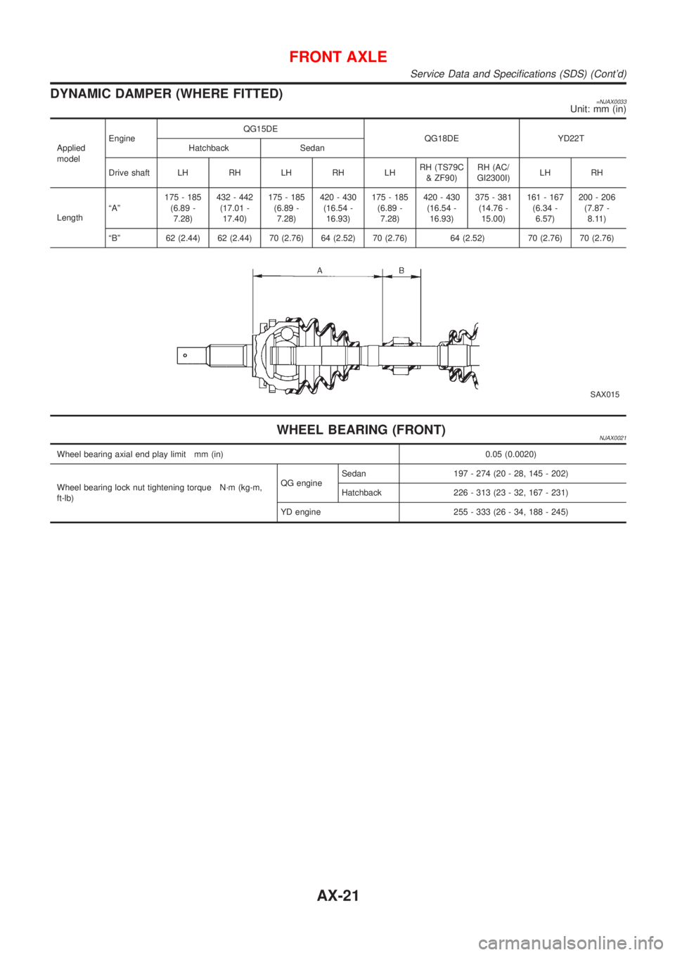
DYNAMIC DAMPER (WHERE FITTED)=NJAX0033Unit: mm (in)
Applied
modelEngineQG15DE
QG18DE YD22T
Hatchback Sedan
Drive shaft LH RH LH RH LHRH (TS79C
& ZF90)RH (AC/
GI2300I)LH RH
LengthªAº175 - 185
(6.89 -
7.28)432 - 442
(17.01 -
17.40)175 - 185
(6.89 -
7.28)420 - 430
(16.54 -
16.93)175 - 185
(6.89 -
7.28)420 - 430
(16.54 -
16.93)375 - 381
(14.76 -
15.00)161 - 167
(6.34 -
6.57)200 - 206
(7.87 -
8.11)
ªBº 62 (2.44) 62 (2.44) 70 (2.76) 64 (2.52) 70 (2.76) 64 (2.52) 70 (2.76) 70 (2.76)
SAX015
WHEEL BEARING (FRONT)NJAX0021
Wheel bearing axial end play limit mm (in) 0.05 (0.0020)
Wheel bearing lock nut tightening torque N´m (kg-m,
ft-lb)QG engineSedan 197 - 274 (20 - 28, 145 - 202)
Hatchback 226 - 313 (23 - 32, 167 - 231)
YD engine 255 - 333 (26 - 34, 188 - 245)
FRONT AXLE
Service Data and Specifications (SDS) (Cont'd)
AX-21
Page 517 of 2898
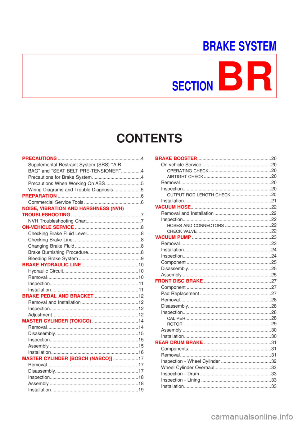
BRAKE SYSTEM
SECTION
BR
CONTENTS
PRECAUTIONS...............................................................4
Supplemental Restraint System (SRS)²AIR
BAG²and²SEAT BELT PRE-TENSIONER²...............4
Precautions for Brake System .....................................4
Precautions When Working On ABS ...........................5
Wiring Diagrams and Trouble Diagnosis .....................5
PREPARATION...............................................................6
Commercial Service Tools ...........................................6
NOISE, VIBRATION AND HARSHNESS (NVH)
TROUBLESHOOTING.....................................................7
NVH Troubleshooting Chart.........................................7
ON-VEHICLE SERVICE..................................................8
Checking Brake Fluid Level.........................................8
Checking Brake Line ...................................................8
Changing Brake Fluid ..................................................8
Brake Burnishing Procedure........................................8
Bleeding Brake System ...............................................9
BRAKE HYDRAULIC LINE...........................................10
Hydraulic Circuit.........................................................10
Removal .....................................................................10
Inspection................................................................... 11
Installation .................................................................. 11
BRAKE PEDAL AND BRACKET..................................12
Removal and Installation ...........................................12
Inspection...................................................................12
Adjustment .................................................................12
MASTER CYLINDER (TOKICO)...................................14
Removal .....................................................................14
Disassembly...............................................................15
Inspection...................................................................15
Assembly ...................................................................15
Installation ..................................................................16
MASTER CYLINDER [BOSCH (NABCO)]...................17
Removal .....................................................................17
Disassembly...............................................................17
Inspection...................................................................18
Assembly ...................................................................18
Installation ..................................................................19BRAKE BOOSTER........................................................20
On-vehicle Service.....................................................20
OPERATING CHECK...............................................20
AIRTIGHT CHECK...................................................20
Removal .....................................................................20
Inspection...................................................................20
OUTPUT ROD LENGTH CHECK..............................20
Installation ..................................................................21
VACUUM HOSE.............................................................22
Removal and Installation ...........................................22
Inspection...................................................................22
HOSES AND CONNECTORS...................................22
CHECK VALVE........................................................22
VACUUM PUMP............................................................23
Removal .....................................................................23
Installation ..................................................................24
Inspection...................................................................24
Component ................................................................25
Disassembly...............................................................25
Assembly ...................................................................25
FRONT DISC BRAKE...................................................27
Component ................................................................27
Pad Replacement ......................................................27
Removal .....................................................................28
Disassembly...............................................................28
Inspection...................................................................28
CALIPER.................................................................28
ROTOR...................................................................29
Assembly ...................................................................30
Installation ..................................................................30
REAR DRUM BRAKE...................................................31
Components...............................................................31
Removal .....................................................................31
Inspection - Wheel Cylinder ......................................32
Wheel Cylinder Overhaul...........................................33
Inspection - Drum ......................................................33
Inspection - Lining .....................................................33
Installation ..................................................................33
Page 536 of 2898

SBR002A
SBR365AA
On-vehicle ServiceNJBR0023OPERATING CHECKNJBR0023S011. Stop engine and depress brake pedal several times. Check
that pedal stroke does not change.
2. Depress brake pedal, then start engine. If pedal goes down
slightly, operation is normal.
AIRTIGHT CHECKNJBR0023S021. Start engine, and stop it after one or two minutes. Depress
brake pedal several times slowly. The pedal should go further
down the first time, and then it should gradually rise thereaf-
ter.
2. Depress brake pedal while engine is running, and stop engine
with pedal depressed. The pedal stroke should not change
after holding pedal down for30 seconds.
SBR232CB
RemovalNJBR0024CAUTION:
+Be careful not to splash brake fluid on painted areas; it
may cause paint damage. If brake fluid is splashed on
painted areas, wash it away with water immediately.
+Be careful not to deform or bend brake pipes, during
removal of booster.
SBR208E
InspectionNJBR0025OUTPUT ROD LENGTH CHECKNJBR0025S011. Apply vacuum of þ66.7 kPa (þ667 mbar, þ500 mmHg, þ19.69
inHg) to brake booster with a handy vacuum pump.
2. Add preload of 19.6 N (2 kg, 4.4 lb) to output rod.
3. Check output rod length.
Specified length:
10.275 - 10.525 mm (0.4045 - 0.4144 in)
BRAKE BOOSTER
On-vehicle Service
BR-20