2001 NISSAN ALMERA wheel alignment
[x] Cancel search: wheel alignmentPage 2567 of 2898
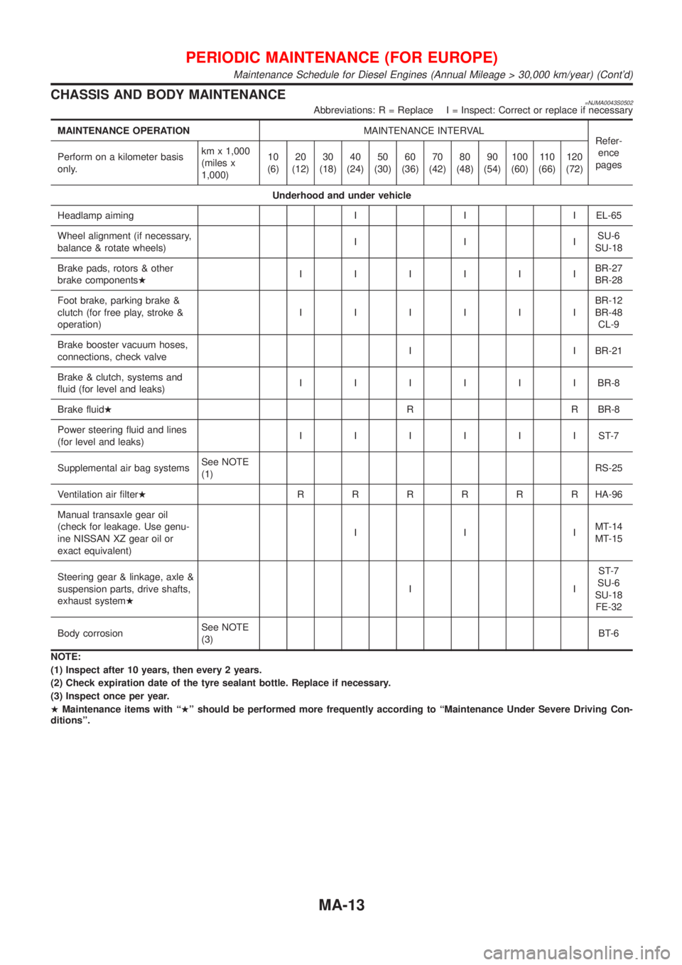
CHASSIS AND BODY MAINTENANCE=NJMA0043S0502Abbreviations: R = Replace I = Inspect: Correct or replace if necessary
MAINTENANCE OPERATIONMAINTENANCE INTERVAL
Refer-
ence
pages Perform on a kilometer basis
only.km x 1,000
(miles x
1,000)10
(6)20
(12)30
(18)40
(24)50
(30)60
(36)70
(42)80
(48)90
(54)100
(60)11 0
(66)120
(72)
Underhood and under vehicle
Headlamp aiming I I I EL-65
Wheel alignment (if necessary,
balance & rotate wheels)IIISU-6
SU-18
Brake pads, rotors & other
brake componentsHIIIIIIBR-27
BR-28
Foot brake, parking brake &
clutch (for free play, stroke &
operation)IIIIIIBR-12
BR-48
CL-9
Brake booster vacuum hoses,
connections, check valveI I BR-21
Brake & clutch, systems and
fluid (for level and leaks)IIIIIIBR-8
Brake fluidHR R BR-8
Power steering fluid and lines
(for level and leaks)IIIIIIST-7
Supplemental air bag systemsSee NOTE
(1)RS-25
Ventilation air filterHRRRRRRHA-96
Manual transaxle gear oil
(check for leakage. Use genu-
ine NISSAN XZ gear oil or
exact equivalent)IIIMT-14
MT-15
Steering gear & linkage, axle &
suspension parts, drive shafts,
exhaust systemHIIST-7
SU-6
SU-18
FE-32
Body corrosionSee NOTE
(3)BT-6
NOTE:
(1) Inspect after 10 years, then every 2 years.
(2) Check expiration date of the tyre sealant bottle. Replace if necessary.
(3) Inspect once per year.
HMaintenance items with ªHº should be performed more frequently according to ªMaintenance Under Severe Driving Con-
ditionsº.
PERIODIC MAINTENANCE (FOR EUROPE)
Maintenance Schedule for Diesel Engines (Annual Mileage > 30,000 km/year) (Cont'd)
MA-13
Page 2733 of 2898
SRS797-A
Maintenance ItemsNJRS0012CAUTION:
Do not use electrical test equipment to check SRS circuit.
1. Check operation of ªAIR BAGº warning lamp.
After turning ignition key to ªONº position, ªAIR BAGº warning
lamp illuminates. The ªAIR BAGº warning lamp will go off after
about 7 seconds if no malfunction is detected. If any of the fol-
lowing ªAIR BAGº warning lamp conditions occur, immediately
check the air bag system. Refer to RS-59 for details.
+The ªAIR BAGº warning lamp does not illuminate when the
ignition switch is turned ªONº.
+The ªAIR BAGº warning lamp does not go off about 7 seconds
after the ignition switch is turned ªONº.
+The ªAIR BAGº warning lamp blinks after about 7 seconds after
the ignition switch is turned ªONº.
2. Visually check SRS components.
1) Diagnosis sensor unit
+Check diagnosis sensor unit and bracket for dents, cracks and
deformities.
+Check connectors for damage, and terminals for deformities.
2) Air bag module and steering wheel
+Remove air bag module from steering wheel, instrument panel
or seatback. Check harness cover and connectors for damage,
terminals for deformities, and harness for binding.
+Install driver air bag module to steering wheel to check fit or
alignment with the wheel.
+Check steering wheel for excessive free play.
+Install front passenger air bag module to instrument panel to
check fit or alignment with the instrument panel.
+Install front side air bag module to seatback to check fit and
alignment with the seat.
3) Spiral cable
+Check spiral cable for dents, cracks, or deformities.
+Check connectors and protective tape for damage.
+Check steering wheel for noise, binding or heavy operation.
4) Main harness, body harness, side air bag module sub-harness
+Check connectors for poor connections, damage, and termi-
nals for deformities.
+Check harnesses for binding, chafing or cut.
5) Front seat belt pre-tensioner
+Check harness cover and connectors for damage, terminals
for deformities, and harness for binding.
+Check belts for damage and anchors for loose mounting.
+Check retractor for smooth operation.
+Perform self-diagnosis for seat belt pre-tensioner using ªAIR
BAGº warning lamp or CONSULT-II.
Refer to ªSRS Operation Checkº for details. (RS-59)
6) Side air bag (satellite) sensor
+Check side air bag (satellite) sensor (including bracket portion)
for dents, cracks or deformities.
+Check connectors for damage, and terminals for deformities.
CAUTION:
Replace previously used special bolts, hex bolts and ground
bolt with new ones.
SUPPLEMENTAL RESTRAINT SYSTEM (SRS)
Maintenance Items
RS-25
Page 2793 of 2898
Collision Diagnosis=NJRS0033FOR FRONTAL COLLISIONNJRS0033S07To repair the SRS, perform the following steps.
When SRS (except the side air bag) is activated in a collision:
1) Replace the diagnosis sensor unit.
2) Remove the air bag modules (except the side air bag module) and front seat belt pre-tensioner assem-
blies.
3) Check the SRS components using the table shown below:
+Replace any SRS components showing visible signs of damage (dents, cracks and deformation).
4) Install new air bag modules (except the side air bag module) and front seat belt pre-tensioner assemblies.
5) Conduct self-diagnosis using CONSULT-II or ªAIR BAGº warning lamp. Refer to ªSRS Operation Checkº
for details (RS-59). Ensure entire SRS operation properly.
When SRS is not activated in a collision:
1) Check the SRS components using the table shown below:
+Replace any SRS components showing visible signs of damage (dents, cracks and deformation).
2) Conduct self-diagnosis using CONSULT-II or ªAIR BAGº warning lamp. Refer to ªSRS Operation Checkº
for details (RS-59). Ensure entire SRS operation properly.
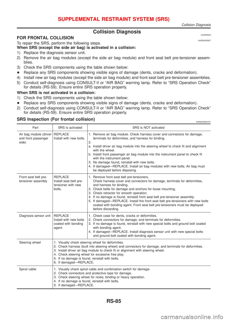
SRS Inspection (For frontal collision)NJRS0033S0701
Part SRS is activated SRS is NOT activated
Air bag module (driver
and front passenger
side)REPLACE
Install with new bolts.1. Remove air bag module. Check harness cover and connectors for damage,
terminals for deformities, and harness for binding.
2.
a. Install driver air bag module into the steering wheel to check fit and alignment
with the wheel.
b. Install front passenger air bag module into the instrument panel to check fit
with the instrument panel.
3. No damage found, reinstall with new bolts.
4. If damagedÐREPLACE. Install air bag modules with new bolts. Air bag must
be deployed before disposing.
Front seat belt pre-
tensioner assemblyREPLACE
Install seat belt pre-
tensioner with new
bolts.1. Remove front seat belt pre-tensioners.
Check harness cover and connectors for damage, terminals for deformities,
and harness for binding.
2. Check belts for damage and anchors for loose mounting.
3. Check retractor for smooth operation.
4. If no damage is found, reinstall front seat belt pre-tensioner assembly.
5. If damagedÐREPLACE. Install the front seat belt pre-tensioners with new bolts
coated with bonding agent. Front seat belt pre-tensioners must be deployed
before discarding.
Diagnosis sensor unit REPLACE
Install with new bolts
coated with bonding
agent.1. Check case for dents, cracks or deformities.
2. Check connectors for damage, and terminals for deformities.
3. If no damage is found, reinstall with new special bolts and ground bolt coated
with bonding agent.
4. If damagedÐREPLACE. Install diagnosis sensor unit with new special bolts
and ground bolt coated with bonding agent.
Steering wheel 1. Visually check steering wheel for deformities.
2. Check harness (built into steering wheel) and connectors for damage, and terminals for deformities.
3. Install driver air bag module to check fit or alignment with steering wheel.
4. Check steering wheel for excessive free play.
5. If no damage is found, reinstall with bolts.
6. If damagedÐREPLACE.
Spiral cable 1. Visually check spiral cable and combination switch for damage.
2. Check connectors and protective tape for damage.
3. Check steering wheel for noise, binding or heavy operation.
4. If no damage is found, reinstall with bolts.
5. If damagedÐREPLACE.
SUPPLEMENTAL RESTRAINT SYSTEM (SRS)
Collision Diagnosis
RS-85
Page 2842 of 2898
SST489B
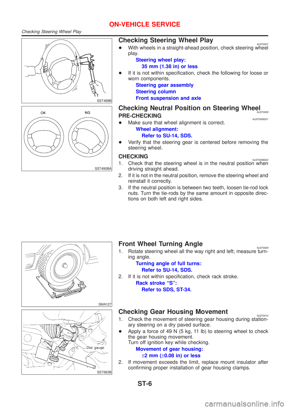
Checking Steering Wheel PlayNJST0007+With wheels in a straight-ahead position, check steering wheel
play.
Steering wheel play:
35 mm (1.38 in) or less
+If it is not within specification, check the following for loose or
worn components.
Steering gear assembly
Steering column
Front suspension and axle
SST490BA
Checking Neutral Position on Steering WheelNJST0008PRE-CHECKINGNJST0008S01+Make sure that wheel alignment is correct.
Wheel alignment:
Refer to SU-14, SDS.
+Verify that the steering gear is centered before removing the
steering wheel.
CHECKINGNJST0008S021. Check that the steering wheel is in the neutral position when
driving straight ahead.
2. If it is not in the neutral position, remove the steering wheel and
reinstall it correctly.
3. If the neutral position is between two teeth, loosen tie-rod lock
nuts. Turn the tie-rods by the same amount in opposite direc-
tions on both left and right sides.
SMA127
Front Wheel Turning AngleNJST00091. Rotate steering wheel all the way right and left; measure turn-
ing angle.
Turning angle of full turns:
Refer to SU-14, SDS.
2. If it is not within specification, check rack stroke.
Rack stroke ªSº:
Refer to SDS, ST-34.
SST663B
Checking Gear Housing MovementNJST00101. Check the movement of steering gear housing during station-
ary steering on a dry paved surface.
+Apply a force of 49 N (5 kg, 11 lb) to steering wheel to check
the gear housing movement.
Turn off ignition key while checking.
Movement of gear housing:
±2mm(±0.08 in) or less
2. If movement exceeds the limit, replace mount insulator after
confirming proper installation of gear housing clamps.
ON-VEHICLE SERVICE
Checking Steering Wheel Play
ST-6
Page 2873 of 2898
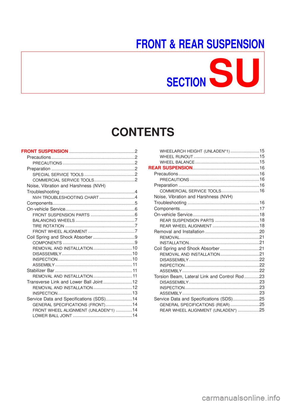
FRONT & REAR SUSPENSION
SECTION
SU
CONTENTS
FRONT SUSPENSION....................................................2
Precautions ..................................................................2
PRECAUTIONS.........................................................2
Preparation ..................................................................2
SPECIAL SERVICE TOOLS........................................2
COMMERCIAL SERVICE TOOLS................................2
Noise, Vibration and Harshness (NVH)
Troubleshooting ...........................................................4
NVH TROUBLESHOOTING CHART............................4
Components.................................................................5
On-vehicle Service.......................................................6
FRONT SUSPENSION PARTS...................................6
BALANCING WHEELS...............................................7
TIRE ROTATION.......................................................7
FRONT WHEEL ALIGNMENT.....................................7
Coil Spring and Shock Absorber .................................9
COMPONENTS.........................................................9
REMOVAL AND INSTALLATION...............................10
DISASSEMBLY........................................................10
INSPECTION...........................................................10
ASSEMBLY............................................................. 11
Stabilizer Bar ............................................................. 11
REMOVAL AND INSTALLATION............................... 11
Transverse Link and Lower Ball Joint .......................12
REMOVAL AND INSTALLATION...............................12
INSPECTION...........................................................13
Service Data and Specifications (SDS).....................14
GENERAL SPECIFICATIONS (FRONT).....................14
FRONT WHEEL ALIGNMENT (UNLADEN*1).............14
LOWER BALL JOINT...............................................14
WHEELARCH HEIGHT (UNLADEN*1).......................15
WHEEL RUNOUT....................................................15
WHEEL BALANCE...................................................15
REAR SUSPENSION.....................................................16
Precautions ................................................................16
PRECAUTIONS.......................................................16
Preparation ................................................................16
COMMERCIAL SERVICE TOOLS..............................16
Noise, Vibration and Harshness (NVH)
Troubleshooting .........................................................16
Components...............................................................17
On-vehicle Service.....................................................18
REAR SUSPENSION PARTS...................................18
REAR WHEEL ALIGNMENT.....................................18
Removal and Installation ...........................................20
REMOVAL...............................................................21
INSTALLATION........................................................21
Coil Spring and Shock Absorber ...............................21
REMOVAL AND INSTALLATION...............................21
DISASSEMBLY........................................................22
INSPECTION...........................................................22
ASSEMBLY.............................................................22
Torsion Beam, Lateral Link and Control Rod ............23
DISASSEMBLY........................................................23
INSPECTION...........................................................23
ASSEMBLY.............................................................23
Service Data and Specifications (SDS).....................25
GENERAL SPECIFICATIONS (REAR).......................25
REAR WHEEL ALIGNMENT (UNLADEN*).................25
Page 2874 of 2898
SBR686C
Precautions
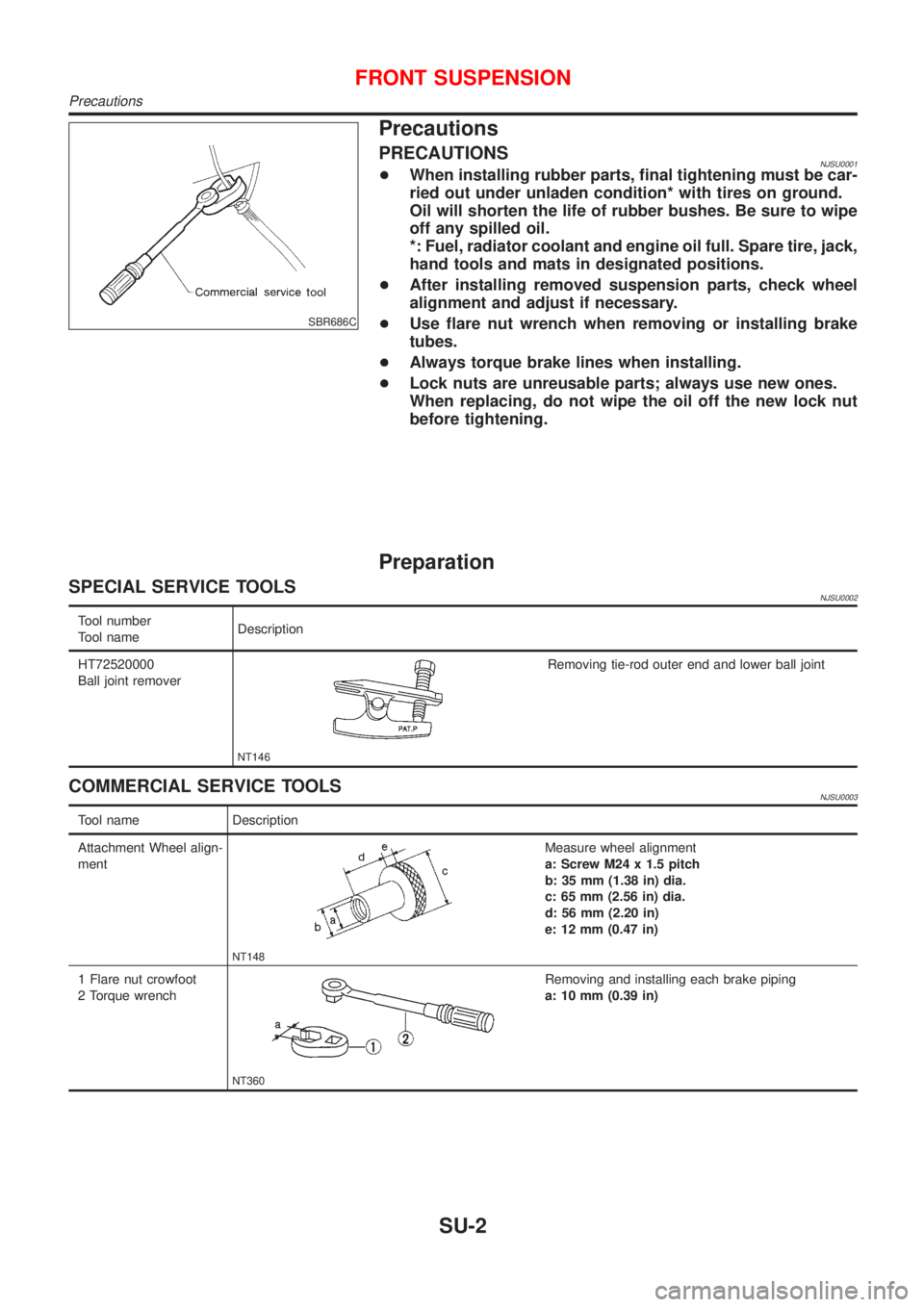
PRECAUTIONSNJSU0001+When installing rubber parts, final tightening must be car-
ried out under unladen condition* with tires on ground.
Oil will shorten the life of rubber bushes. Be sure to wipe
off any spilled oil.
*: Fuel, radiator coolant and engine oil full. Spare tire, jack,
hand tools and mats in designated positions.
+After installing removed suspension parts, check wheel
alignment and adjust if necessary.
+Use flare nut wrench when removing or installing brake
tubes.
+Always torque brake lines when installing.
+Lock nuts are unreusable parts; always use new ones.
When replacing, do not wipe the oil off the new lock nut
before tightening.
Preparation
SPECIAL SERVICE TOOLSNJSU0002
Tool number
Tool nameDescription
HT72520000
Ball joint remover
NT146
Removing tie-rod outer end and lower ball joint
COMMERCIAL SERVICE TOOLSNJSU0003
Tool name Description
Attachment Wheel align-
ment
NT148
Measure wheel alignment
a: Screw M24 x 1.5 pitch
b: 35 mm (1.38 in) dia.
c: 65 mm (2.56 in) dia.
d: 56 mm (2.20 in)
e: 12 mm (0.47 in)
1 Flare nut crowfoot
2 Torque wrench
NT360
Removing and installing each brake piping
a: 10 mm (0.39 in)
FRONT SUSPENSION
Precautions
SU-2
Page 2876 of 2898
Noise, Vibration and Harshness (NVH)
Troubleshooting
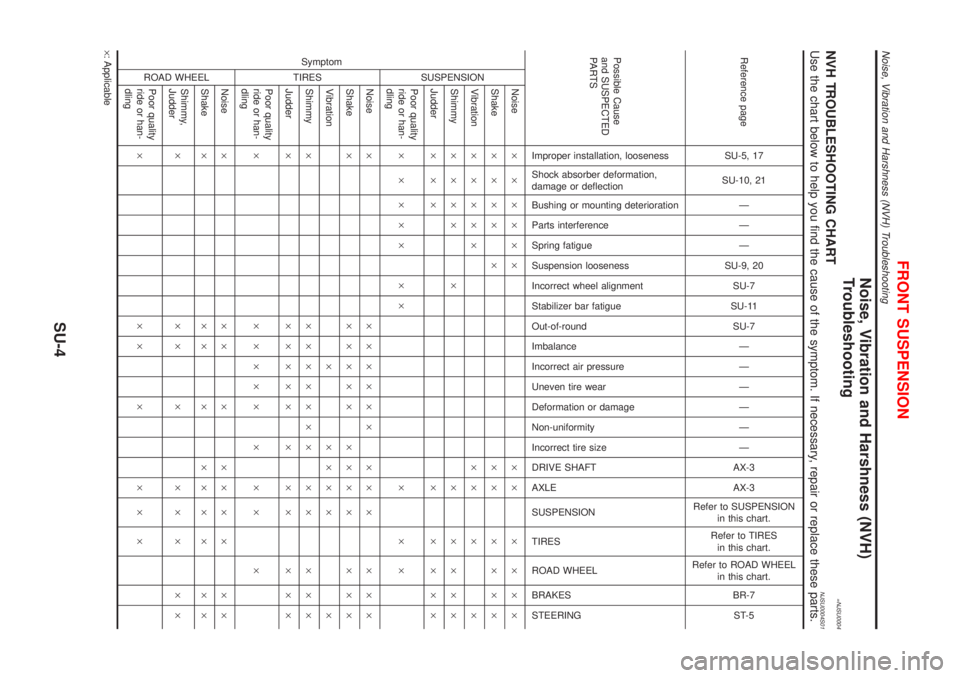
=NJSU0004NVH TROUBLESHOOTING CHARTNJSU0004S01Use the chart below to help you find the cause of the symptom. If necessary, repair or replace these parts.
Reference page
SU-5, 17
SU-10, 21
Ð
Ð
Ð
SU-9, 20
SU-7
SU-11
SU-7
Ð
Ð
Ð
Ð
Ð
Ð
AX-3
AX-3
Refer to SUSPENSION
in this chart.
Refer to TIRES
in this chart.
Refer to ROAD WHEEL
in this chart.
BR-7
ST-5
Possible Cause
and SUSPECTED
PA R T S
Improper installation, looseness
Shock absorber deformation,
damage or deflection
Bushing or mounting deterioration
Parts interference
Spring fatigue
Suspension looseness
Incorrect wheel alignment
Stabilizer bar fatigue
Out-of-round
Imbalance
Incorrect air pressure
Uneven tire wear
Deformation or damage
Non-uniformity
Incorrect tire size
DRIVE SHAFT
AXLE
SUSPENSION
TIRES
ROAD WHEEL
BRAKES
STEERING Symptom
SUSPENSION
Noise´ ´ ´´´´ ´´ ´ ´ ´´
Shake´ ´ ´´ ´ ´´ ´ ´ ´´
Vibration´ ´ ´´´ ´´ ´ ´
Shimmy´´´´ ´ ´ ´ ´´´
Judder´´´ ´ ´ ´´´
Poor quality
ride or han-
dling´ ´ ´´´ ´´ ´ ´ ´
TIRES
Noise´ ´´´´´´ ´´ ´ ´ ´´
Shake´ ´´´´´ ´´´ ´ ´ ´´
Vibration´ ´´´ ´ ´
Shimmy´ ´´´´´´´ ´ ´ ´ ´´
Judder´ ´´´´´ ´ ´ ´ ´ ´´
Poor quality
ride or han-
dling´ ´´´´´ ´ ´ ´ ´
ROAD WHEEL
Noise´ ´´´´´´´´´
Shake´ ´´´´´´´´´
Shimmy,
Judder´´´´´´´´´
Poor quality
ride or han-
dling´´´´´´´
´: Applicable
FRONT SUSPENSION
Noise, Vibration and Harshness (NVH) Troubleshooting
SU-4
Page 2879 of 2898
SFA975B
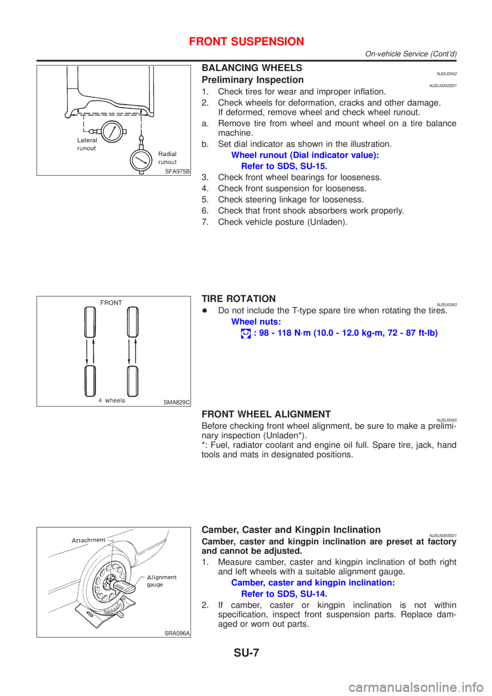
BALANCING WHEELSNJSU0042Preliminary InspectionNJSU0042S011. Check tires for wear and improper inflation.
2. Check wheels for deformation, cracks and other damage.
If deformed, remove wheel and check wheel runout.
a. Remove tire from wheel and mount wheel on a tire balance
machine.
b. Set dial indicator as shown in the illustration.
Wheel runout (Dial indicator value):
Refer to SDS, SU-15.
3. Check front wheel bearings for looseness.
4. Check front suspension for looseness.
5. Check steering linkage for looseness.
6. Check that front shock absorbers work properly.
7. Check vehicle posture (Unladen).
SMA829C
TIRE ROTATIONNJSU0043+Do not include the T-type spare tire when rotating the tires.
Wheel nuts:
: 98 - 118 N´m (10.0 - 12.0 kg-m, 72 - 87 ft-lb)
FRONT WHEEL ALIGNMENTNJSU0045Before checking front wheel alignment, be sure to make a prelimi-
nary inspection (Unladen*).
*: Fuel, radiator coolant and engine oil full. Spare tire, jack, hand
tools and mats in designated positions.
SRA096A
Camber, Caster and Kingpin InclinationNJSU0045S01Camber, caster and kingpin inclination are preset at factory
and cannot be adjusted.
1. Measure camber, caster and kingpin inclination of both right
and left wheels with a suitable alignment gauge.
Camber, caster and kingpin inclination:
Refer to SDS, SU-14.
2. If camber, caster or kingpin inclination is not within
specification, inspect front suspension parts. Replace dam-
aged or worn out parts.
FRONT SUSPENSION
On-vehicle Service (Cont'd)
SU-7