2001 NISSAN ALMERA mirror
[x] Cancel search: mirrorPage 1854 of 2898
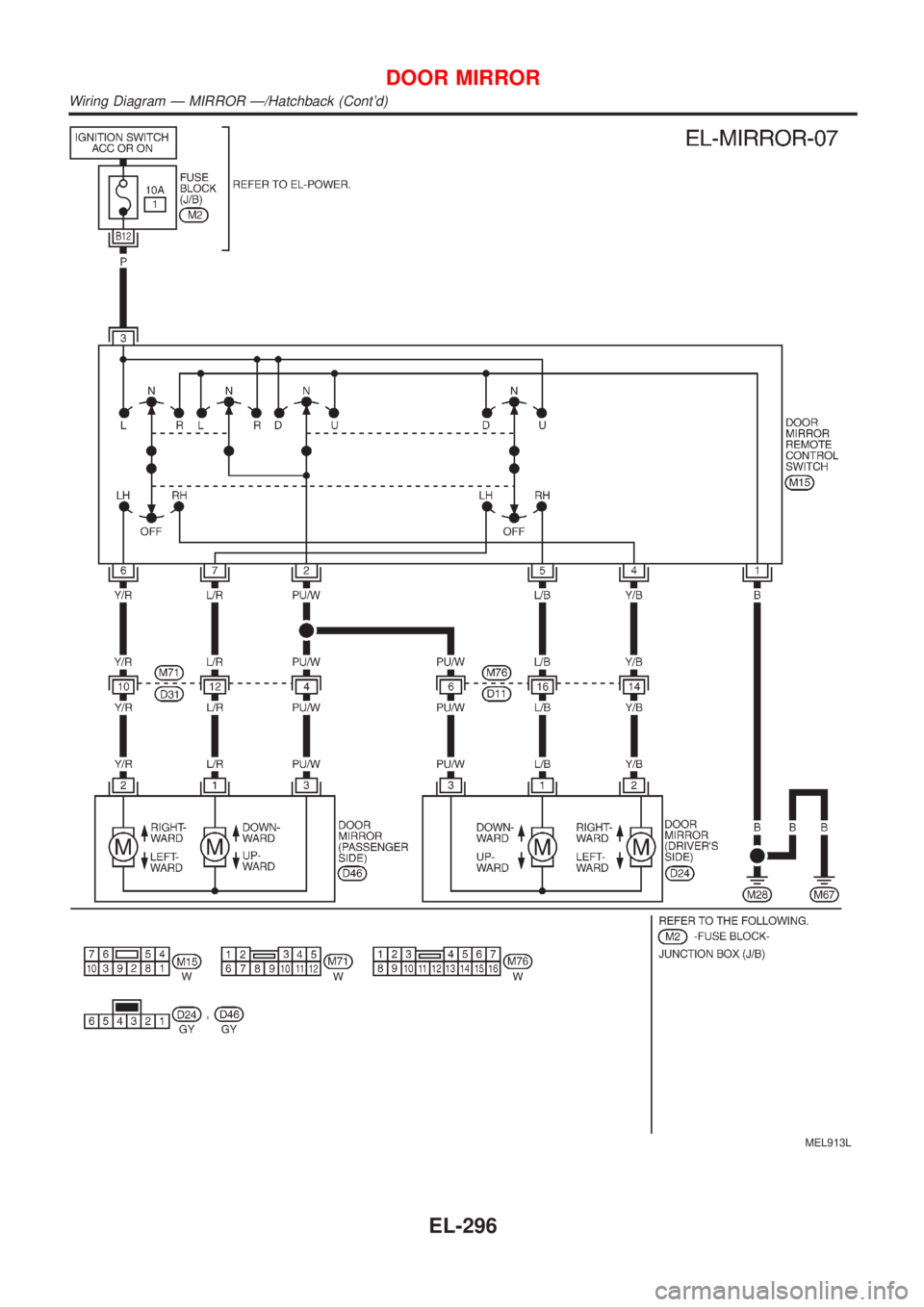
MEL913L
DOOR MIRROR
Wiring Diagram Ð MIRROR Ð/Hatchback (Cont'd)
EL-296
Page 1975 of 2898
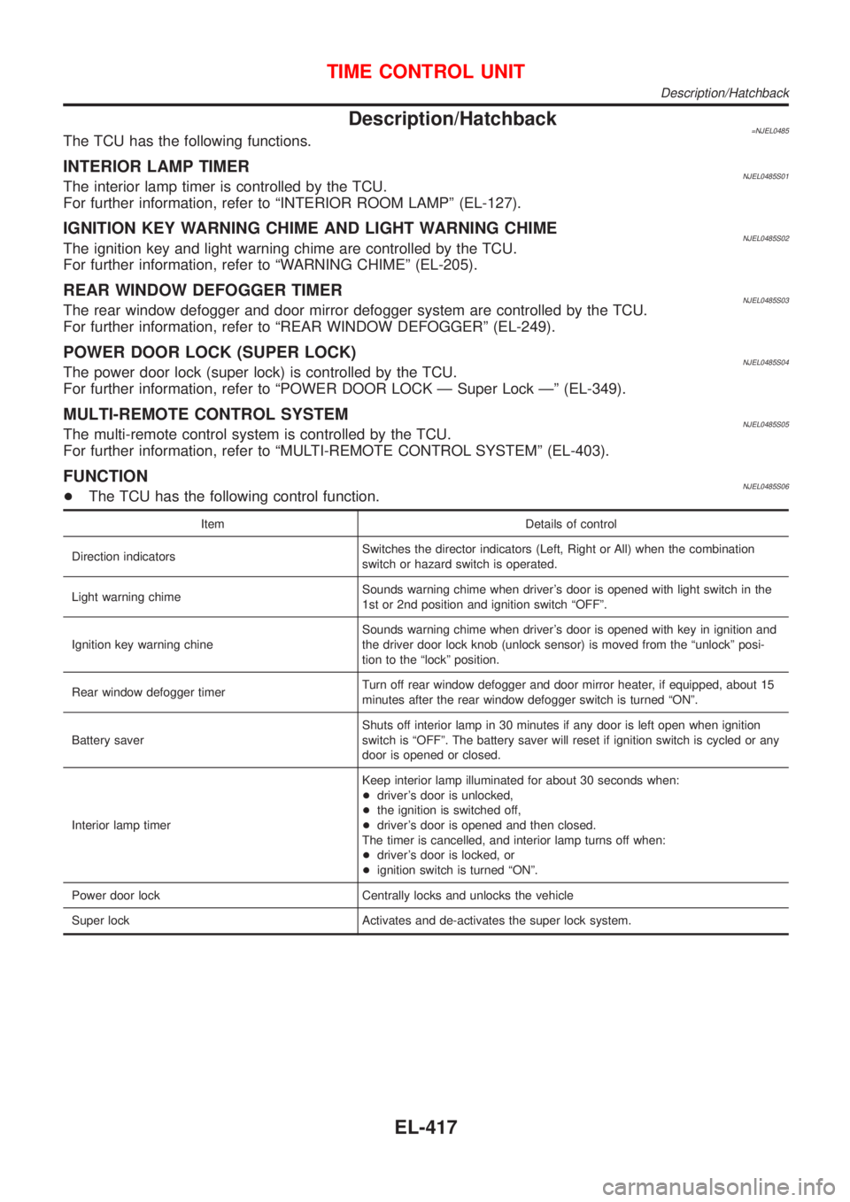
Description/Hatchback=NJEL0485The TCU has the following functions.
INTERIOR LAMP TIMERNJEL0485S01The interior lamp timer is controlled by the TCU.
For further information, refer to ªINTERIOR ROOM LAMPº (EL-127).
IGNITION KEY WARNING CHIME AND LIGHT WARNING CHIMENJEL0485S02The ignition key and light warning chime are controlled by the TCU.
For further information, refer to ªWARNING CHIMEº (EL-205).
REAR WINDOW DEFOGGER TIMERNJEL0485S03The rear window defogger and door mirror defogger system are controlled by the TCU.
For further information, refer to ªREAR WINDOW DEFOGGERº (EL-249).
POWER DOOR LOCK (SUPER LOCK)NJEL0485S04The power door lock (super lock) is controlled by the TCU.
For further information, refer to ªPOWER DOOR LOCK Ð Super Lock к (EL-349).
MULTI-REMOTE CONTROL SYSTEMNJEL0485S05The multi-remote control system is controlled by the TCU.
For further information, refer to ªMULTI-REMOTE CONTROL SYSTEMº (EL-403).
FUNCTIONNJEL0485S06+The TCU has the following control function.
Item Details of control
Direction indicatorsSwitches the director indicators (Left, Right or All) when the combination
switch or hazard switch is operated.
Light warning chimeSounds warning chime when driver's door is opened with light switch in the
1st or 2nd position and ignition switch ªOFFº.
Ignition key warning chineSounds warning chime when driver's door is opened with key in ignition and
the driver door lock knob (unlock sensor) is moved from the ªunlockº posi-
tion to the ªlockº position.
Rear window defogger timerTurn off rear window defogger and door mirror heater, if equipped, about 15
minutes after the rear window defogger switch is turned ªONº.
Battery saverShuts off interior lamp in 30 minutes if any door is left open when ignition
switch is ªOFFº. The battery saver will reset if ignition switch is cycled or any
door is opened or closed.
Interior lamp timerKeep interior lamp illuminated for about 30 seconds when:
+driver's door is unlocked,
+the ignition is switched off,
+driver's door is opened and then closed.
The timer is cancelled, and interior lamp turns off when:
+driver's door is locked, or
+ignition switch is turned ªONº.
Power door lock Centrally locks and unlocks the vehicle
Super lock Activates and de-activates the super lock system.
TIME CONTROL UNIT
Description/Hatchback
EL-417
Page 2132 of 2898
NJEL0144
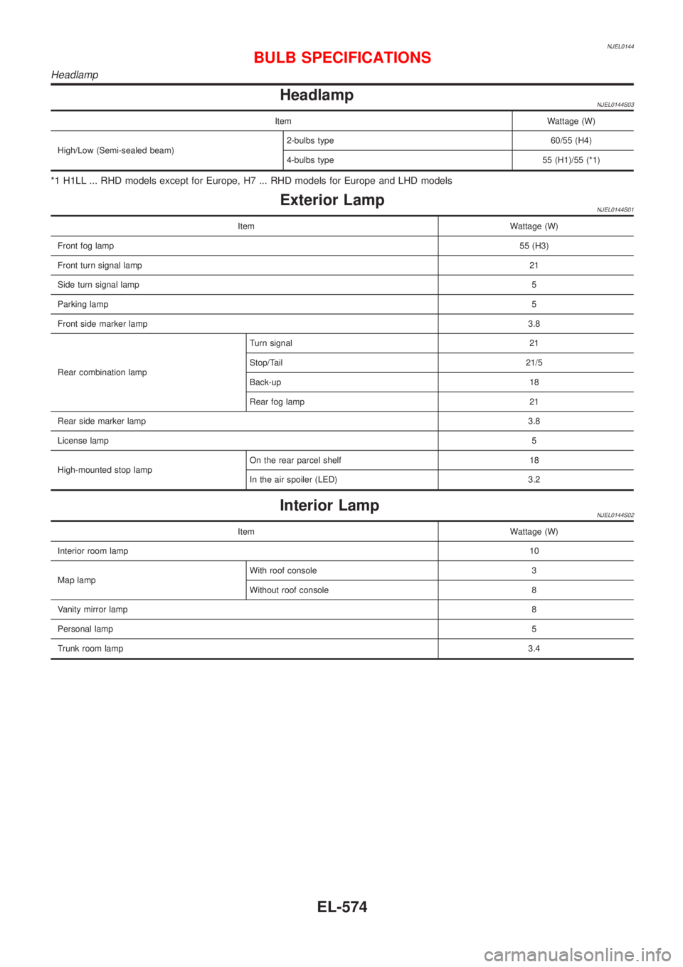
HeadlampNJEL0144S03
Item Wattage (W)
High/Low (Semi-sealed beam)2-bulbs type 60/55 (H4)
4-bulbs type 55 (H1)/55 (*1)
*1 H1LL ... RHD models except for Europe, H7 ... RHD models for Europe and LHD models
Exterior LampNJEL0144S01
Item Wattage (W)
Front fog lamp55 (H3)
Front turn signal lamp21
Side turn signal lamp5
Parking lamp5
Front side marker lamp3.8
Rear combination lampTurn signal 21
Stop/Tail 21/5
Back-up 18
Rear fog lamp 21
Rear side marker lamp3.8
License lamp5
High-mounted stop lampOn the rear parcel shelf 18
In the air spoiler (LED) 3.2
Interior LampNJEL0144S02
Item Wattage (W)
Interior room lamp10
Map lampWith roof console 3
Without roof console 8
Vanity mirror lamp8
Personal lamp5
Trunk room lamp3.4
BULB SPECIFICATIONS
Headlamp
EL-574
Page 2133 of 2898
NJEL0311
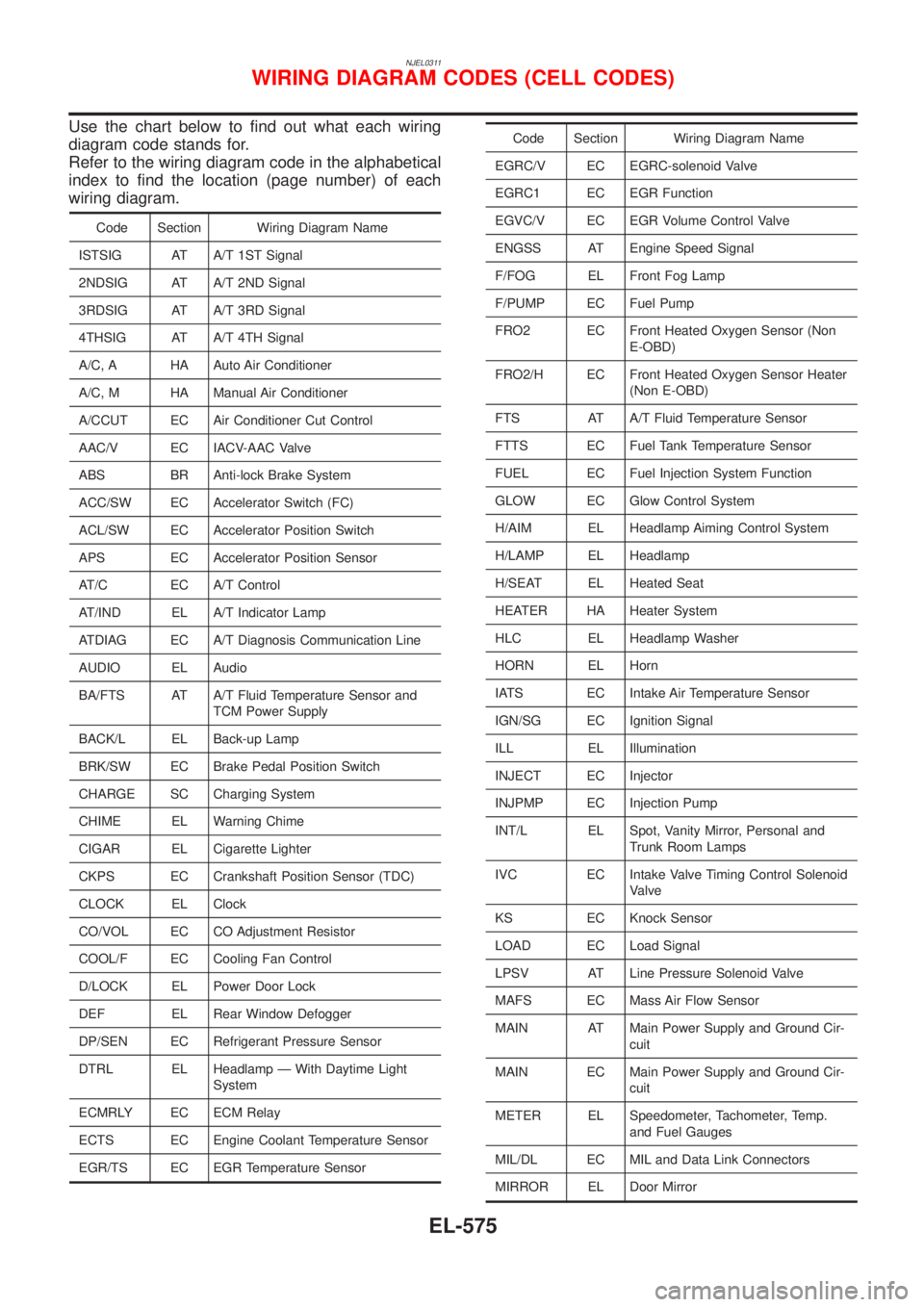
Use the chart below to find out what each wiring
diagram code stands for.
Refer to the wiring diagram code in the alphabetical
index to find the location (page number) of each
wiring diagram.
Code Section Wiring Diagram Name
ISTSIG AT A/T 1ST Signal
2NDSIG AT A/T 2ND Signal
3RDSIG AT A/T 3RD Signal
4THSIG AT A/T 4TH Signal
A/C, A HA Auto Air Conditioner
A/C, M HA Manual Air Conditioner
A/CCUT EC Air Conditioner Cut Control
AAC/V EC IACV-AAC Valve
ABS BR Anti-lock Brake System
ACC/SW EC Accelerator Switch (FC)
ACL/SW EC Accelerator Position Switch
APS EC Accelerator Position Sensor
AT/C EC A/T Control
AT/IND EL A/T Indicator Lamp
ATDIAG EC A/T Diagnosis Communication Line
AUDIO EL Audio
BA/FTS AT A/T Fluid Temperature Sensor and
TCM Power Supply
BACK/L EL Back-up Lamp
BRK/SW EC Brake Pedal Position Switch
CHARGE SC Charging System
CHIME EL Warning Chime
CIGAR EL Cigarette Lighter
CKPS EC Crankshaft Position Sensor (TDC)
CLOCK EL Clock
CO/VOL EC CO Adjustment Resistor
COOL/F EC Cooling Fan Control
D/LOCK EL Power Door Lock
DEF EL Rear Window Defogger
DP/SEN EC Refrigerant Pressure Sensor
DTRL EL Headlamp Ð With Daytime Light
System
ECMRLY EC ECM Relay
ECTS EC Engine Coolant Temperature Sensor
EGR/TS EC EGR Temperature Sensor
Code Section Wiring Diagram Name
EGRC/V EC EGRC-solenoid Valve
EGRC1 EC EGR Function
EGVC/V EC EGR Volume Control Valve
ENGSS AT Engine Speed Signal
F/FOG EL Front Fog Lamp
F/PUMP EC Fuel Pump
FRO2 EC Front Heated Oxygen Sensor (Non
E-OBD)
FRO2/H EC Front Heated Oxygen Sensor Heater
(Non E-OBD)
FTS AT A/T Fluid Temperature Sensor
FTTS EC Fuel Tank Temperature Sensor
FUEL EC Fuel Injection System Function
GLOW EC Glow Control System
H/AIM EL Headlamp Aiming Control System
H/LAMP EL Headlamp
H/SEAT EL Heated Seat
HEATER HA Heater System
HLC EL Headlamp Washer
HORN EL Horn
IATS EC Intake Air Temperature Sensor
IGN/SG EC Ignition Signal
ILL EL Illumination
INJECT EC Injector
INJPMP EC Injection Pump
INT/L EL Spot, Vanity Mirror, Personal and
Trunk Room Lamps
IVC EC Intake Valve Timing Control Solenoid
Valve
KS EC Knock Sensor
LOAD EC Load Signal
LPSV AT Line Pressure Solenoid Valve
MAFS EC Mass Air Flow Sensor
MAIN AT Main Power Supply and Ground Cir-
cuit
MAIN EC Main Power Supply and Ground Cir-
cuit
METER EL Speedometer, Tachometer, Temp.
and Fuel Gauges
MIL/DL EC MIL and Data Link Connectors
MIRROR EL Door Mirror
WIRING DIAGRAM CODES (CELL CODES)
EL-575
Page 2501 of 2898
C
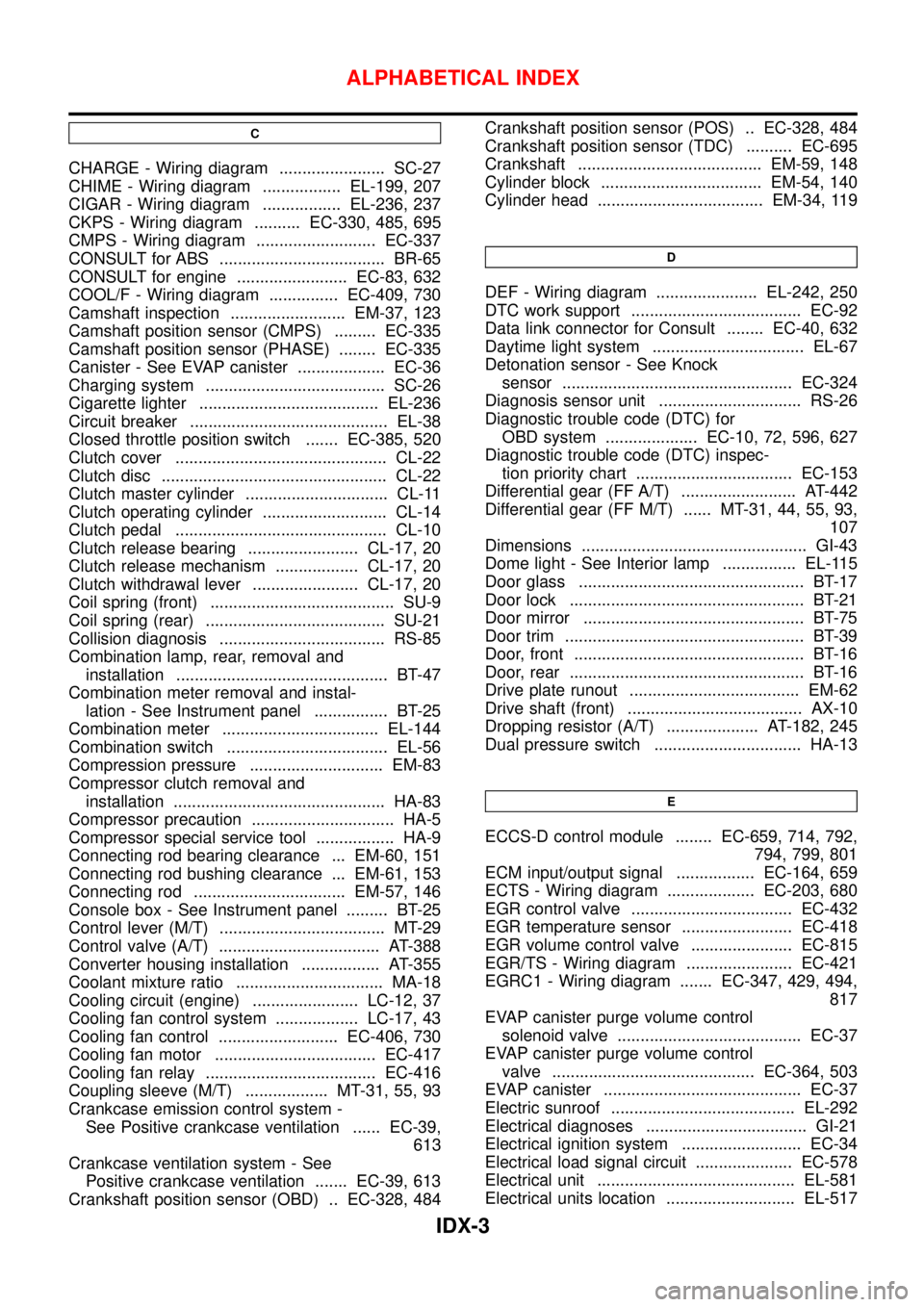
CHARGE - Wiring diagram ....................... SC-27
CHIME - Wiring diagram ................. EL-199, 207
CIGAR - Wiring diagram ................. EL-236, 237
CKPS - Wiring diagram .......... EC-330, 485, 695
CMPS - Wiring diagram .......................... EC-337
CONSULT for ABS .................................... BR-65
CONSULT for engine ........................ EC-83, 632
COOL/F - Wiring diagram ............... EC-409, 730
Camshaft inspection ......................... EM-37, 123
Camshaft position sensor (CMPS) ......... EC-335
Camshaft position sensor (PHASE) ........ EC-335
Canister - See EVAP canister ................... EC-36
Charging system ....................................... SC-26
Cigarette lighter ....................................... EL-236
Circuit breaker ........................................... EL-38
Closed throttle position switch ....... EC-385, 520
Clutch cover .............................................. CL-22
Clutch disc ................................................. CL-22
Clutch master cylinder ............................... CL-11
Clutch operating cylinder ........................... CL-14
Clutch pedal .............................................. CL-10
Clutch release bearing ........................ CL-17, 20
Clutch release mechanism .................. CL-17, 20
Clutch withdrawal lever ....................... CL-17, 20
Coil spring (front) ........................................ SU-9
Coil spring (rear) ....................................... SU-21
Collision diagnosis .................................... RS-85
Combination lamp, rear, removal and
installation .............................................. BT-47
Combination meter removal and instal-
lation - See Instrument panel ................ BT-25
Combination meter .................................. EL-144
Combination switch ................................... EL-56
Compression pressure ............................. EM-83
Compressor clutch removal and
installation .............................................. HA-83
Compressor precaution ............................... HA-5
Compressor special service tool ................. HA-9
Connecting rod bearing clearance ... EM-60, 151
Connecting rod bushing clearance ... EM-61, 153
Connecting rod ................................. EM-57, 146
Console box - See Instrument panel ......... BT-25
Control lever (M/T) .................................... MT-29
Control valve (A/T) ................................... AT-388
Converter housing installation ................. AT-355
Coolant mixture ratio ................................ MA-18
Cooling circuit (engine) ....................... LC-12, 37
Cooling fan control system .................. LC-17, 43
Cooling fan control .......................... EC-406, 730
Cooling fan motor ................................... EC-417
Cooling fan relay ..................................... EC-416
Coupling sleeve (M/T) .................. MT-31, 55, 93
Crankcase emission control system -
See Positive crankcase ventilation ...... EC-39,
613
Crankcase ventilation system - See
Positive crankcase ventilation ....... EC-39, 613
Crankshaft position sensor (OBD) .. EC-328, 484Crankshaft position sensor (POS) .. EC-328, 484
Crankshaft position sensor (TDC) .......... EC-695
Crankshaft ........................................ EM-59, 148
Cylinder block ................................... EM-54, 140
Cylinder head .................................... EM-34, 119
D
DEF - Wiring diagram ...................... EL-242, 250
DTC work support ..................................... EC-92
Data link connector for Consult ........ EC-40, 632
Daytime light system ................................. EL-67
Detonation sensor - See Knock
sensor .................................................. EC-324
Diagnosis sensor unit ............................... RS-26
Diagnostic trouble code (DTC) for
OBD system .................... EC-10, 72, 596, 627
Diagnostic trouble code (DTC) inspec-
tion priority chart .................................. EC-153
Differential gear (FF A/T) ......................... AT-442
Differential gear (FF M/T) ...... MT-31, 44, 55, 93,
107
Dimensions ................................................. GI-43
Dome light - See Interior lamp ................ EL-115
Door glass ................................................. BT-17
Door lock ................................................... BT-21
Door mirror ................................................ BT-75
Door trim .................................................... BT-39
Door, front .................................................. BT-16
Door, rear ................................................... BT-16
Drive plate runout ..................................... EM-62
Drive shaft (front) ...................................... AX-10
Dropping resistor (A/T) .................... AT-182, 245
Dual pressure switch ................................ HA-13
E
ECCS-D control module ........ EC-659, 714, 792,
794, 799, 801
ECM input/output signal ................. EC-164, 659
ECTS - Wiring diagram ................... EC-203, 680
EGR control valve ................................... EC-432
EGR temperature sensor ........................ EC-418
EGR volume control valve ...................... EC-815
EGR/TS - Wiring diagram ....................... EC-421
EGRC1 - Wiring diagram ....... EC-347, 429, 494,
817
EVAP canister purge volume control
solenoid valve ........................................ EC-37
EVAP canister purge volume control
valve ............................................ EC-364, 503
EVAP canister ........................................... EC-37
Electric sunroof ........................................ EL-292
Electrical diagnoses ................................... GI-21
Electrical ignition system .......................... EC-34
Electrical load signal circuit ..................... EC-578
Electrical unit ........................................... EL-581
Electrical units location ............................ EL-517
ALPHABETICAL INDEX
IDX-3
Page 2503 of 2898
Headlining - See Roof trim ........................ BT-43
Heated oxygen sensor (HO2S)
(front) .......... EC-216, 224, 230, 236, 245, 450
Heated oxygen sensor (HO2S) heater
(front) ........................................... EC-252, 457
Heated oxygen sensor (HO2S) heater
(rear) ............................................ EC-291, 469
Heated oxygen sensor (rear) ......... EC-258, 267,
275, 284, 462
Heated seat ............................................. EL-288
Height (Dimensions) ................................... GI-43
High clutch ............................................... AT-407
Hood ............................................................ BT-7
Horn ......................................................... EL-234
How to erase DTC for OBD system .. EC-70, 73,
627
I
IACV-AAC valve .............................. EC-376, 511
IATS - Wiring diagram .................... EC-196, 444
IGN/SG - Wiring diagram ........................ EC-548
ILL - Wiring diagram ................................ EL-112
INJECT - Wiring diagram ........................ EC-542
INT/L - Wiring diagram .................... EL-141, 143
IVC - Wiring diagram ...................... EC-395, 527
Identification plate ...................................... GI-40
Idle air control (IAC) system ........... EC-376, 511
Idle air control valve (IACV) ............ EC-376, 511
Idle speed ......................................... EC-43, 641
Ignition timing ............................................ EC-43
Illumination ............................................... EL-108
Injection nozzle ....................................... EC-614
Injector removal and installation ............... EC-41
Input shaft (FF M/T) ............... MT-36, 64, 93, 98
Instrument panel ........................................ BT-25
Intake air temperature sensor ......... EC-194, 442
Intake valve timing control solenoid
valve ............................................ EC-393, 526
Interior lamp on-off control .............. EL-116, 128
Interior lamp ............................................. EL-115
Interior ........................................................ BT-31
J
Jacking points ............................................ GI-45
Joint connector (J/C) ............................... EL-583
Junction box (J/B) .................................... EL-577
K
Keyless entry system - See Multi-remote control
system ..................................................... EL-392
Knock sensor (KS) .......................... EC-324, 325
Knuckle spindle ........................................... AX-5
L
LOAD - Wiring diagram .......................... EC-579
Length (Dimensions) .................................. GI-43
License lamp ............................................. EL-81
Lifting points ............................................... GI-46
Line pressure solenoid valve ................... AT-232
Line pressure test (A/T) ............................. AT-84
Liquid gasket application ...................... EM-4, 77
Location of electrical units ....................... EL-517
Lock, door .................................................. BT-21
Low and reverse brake ............................ AT-419
Lubricant (R134a) A/C .............................. HA-80
Lubricants ................................................. MA-16
Lubrication circuit (engine) .................... LC-4, 27
M
M/T major overhaul ....................... MT-30, 54, 92
M/T removal and installation ..................... MT-23
MAFS - Wiring diagram .................. EC-189, 673
MAIN - Wiring diagram ................... EC-178, 666
MAJOR OVERHALL ................................ AT-357
METER - Wiring diagram ........................ EL-151
MIL & Data link connectors circuit .......... EC-591
MIL/DL - Wiring diagram ................. EC-591, 831
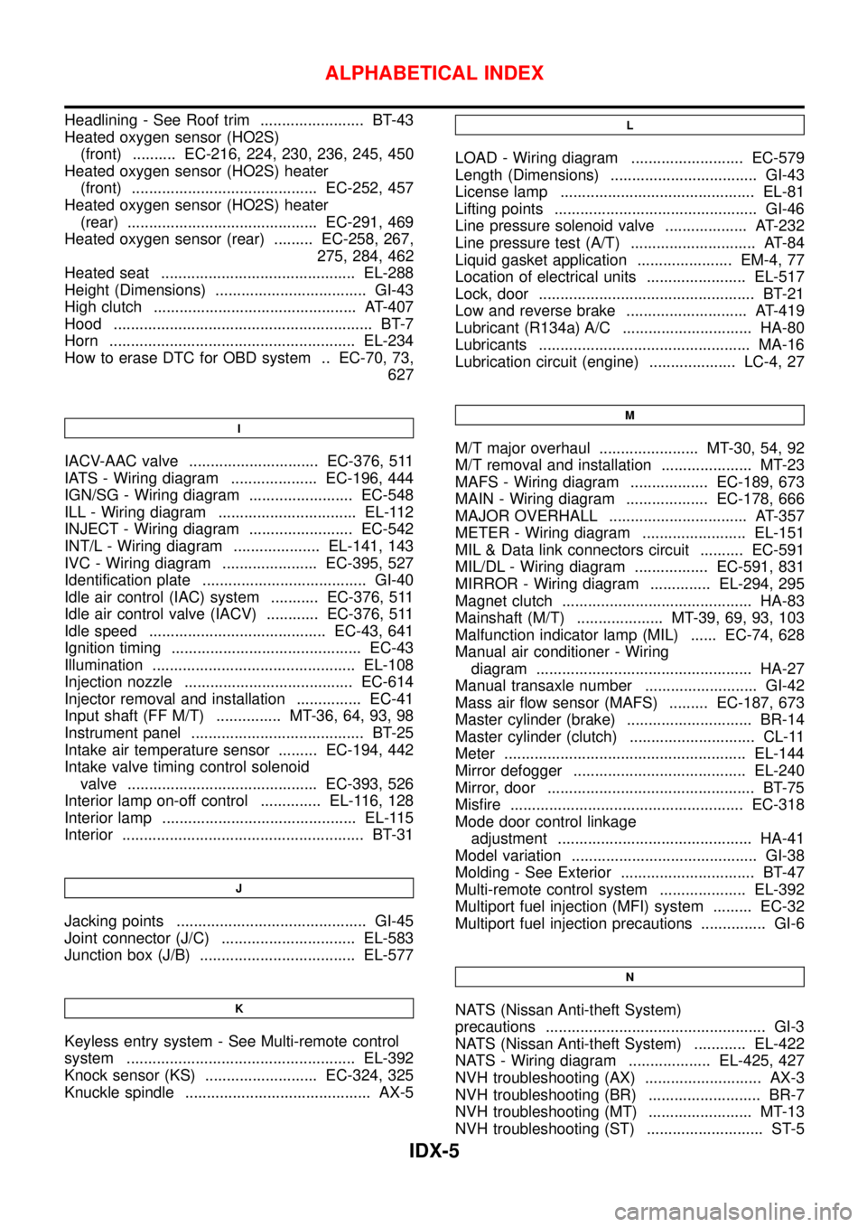
MIRROR - Wiring diagram .............. EL-294, 295
Magnet clutch ............................................ HA-83
Mainshaft (M/T) .................... MT-39, 69, 93, 103
Malfunction indicator lamp (MIL) ...... EC-74, 628
Manual air conditioner - Wiring
diagram .................................................. HA-27
Manual transaxle number .......................... GI-42
Mass air flow sensor (MAFS) ......... EC-187, 673
Master cylinder (brake) ............................. BR-14
Master cylinder (clutch) ............................. CL-11
Meter ........................................................ EL-144
Mirror defogger ........................................ EL-240
Mirror, door ................................................ BT-75
Misfire ...................................................... EC-318
Mode door control linkage
adjustment ............................................. HA-41
Model variation ........................................... GI-38
Molding - See Exterior ............................... BT-47
Multi-remote control system .................... EL-392
Multiport fuel injection (MFI) system ......... EC-32
Multiport fuel injection precautions ............... GI-6
N
NATS (Nissan Anti-theft System)
precautions ................................................... GI-3
NATS (Nissan Anti-theft System) ............ EL-422
NATS - Wiring diagram ................... EL-425, 427
NVH troubleshooting (AX) ........................... AX-3
NVH troubleshooting (BR) .......................... BR-7
NVH troubleshooting (MT) ........................ MT-13
NVH troubleshooting (ST) ........................... ST-5
ALPHABETICAL INDEX
IDX-5
Page 2504 of 2898
NVH troubleshooting (SU) ........................ SU-16
NVH troubleshooting (CL) ........................... CL-4
NVIS (Nissan vehicle immobiliser sys-
tem) precautions ....................................... GI-3
Neutral position switch .................... EC-437, 536
O
Oil pan (engine) .................................. EM-20, 89
Oil pressure (engine) ............................ LC-5, 28
Oil pump (A/T) ......................................... AT-384
Oil pump (engine) ................................. LC-5, 28
Oil pump regulator valve (engine) ......... LC-8, 30
Oil seal replacement (engine) .................. EM-32
On board diagnostic system ............. EC-59, 627
Operating cylinder (clutch) ........................ CL-14
Overdrive control switch .......................... AT-341
Overrun clutch .......................................... AT-412
P
P/ANT - Wiring diagram .......................... EL-282
PCV (positive crankcase
ventilation) ..................................... EC-39, 613
PGC/V - Wiring diagram ................. EC-366, 505
PNP/SW - Wiring diagram ...... EC-439, 537, 826
POWER - Wiring diagram ................... EL-11, 28
PST/SW - Wiring diagram ....................... EC-568
Park/Neutral position switch ... EC-437, 536, 826
Park/neutral position switch (A/T) ............ AT-183
Park/neutral position switch (M/T) ............ MT-21
Parking brake control ................................ BR-47
Parking lamp .............................................. EL-81
Piston assembly ............................... EM-62, 155
Piston pin inspection ........................ EM-56, 145
Piston ring inspection ....................... EM-56, 145
Piston to bore clearance .................. EM-58, 147
Power antenna ........................................ EL-282
Power door lock ....................................... EL-314
Power door mirror .................................... EL-294
Power steering fluid level ............................ ST-7
Power steering gear .................................. ST-16
Power steering hydraulic pressure .............. ST-9
Power steering oil pressure switch ......... EC-567
Power steering oil pump ............................ ST-25
Power steering system bleeding ................. ST-8
Power supply routing ................................. EL-10
Power window ......................................... EL-298
Precautions (General) .................................. GI-4
Pressure plate - See Clutch cover ............ CL-22
Priming pump .................................. EC-625, 641
Q
Quick-glow system .................................. EC-806
R
RR02 - Wiring diagram .......... EC-261, 270, 278,
286, 463
RR02/H - Wiring diagram ............... EC-293, 470
Radiator ............................................... LC-16, 42
Radio - See Audio ................................... EL-258
Rear air spoiler .......................................... BT-47
Rear axle (disc brake type) ....................... AX-24
Rear axle ................................................... AX-22
Rear bumper .............................................. BT-10
Rear combination lamp removal and
installation .............................................. BT-47
Rear disc brake .................................. BR-35, 43
Rear door ................................................... BT-16
Rear drum brake ....................................... BR-31
Rear heated oxygen sensor (HO2S)
heater .......................................... EC-291, 469
Rear heated oxygen sensor (HO2S) ..... EC-258,
267, 275, 284, 462
Rear seat belt ............................................ RS-11
Rear seat ................................................... BT-60
Rear suspension ....................................... SU-16
Rear window defogger ............................ EL-240
Rear window .............................................. BT-71
Refrigerant connection precaution .............. HA-3
Refrigerant general precaution ................... HA-2
Refrigerant lines ........................................ HA-91
Refrigeration cycle .................................... HA-13
Release bearing (clutch) ..................... CL-17, 20
Removal and installation (A/T) ................ AT-354
Reverse clutch ......................................... AT-403
Reverse idler shaft (M/T) .............. MT-30, 54, 93
Reverse lamp switch (M/T) - See
Back-up lamp switch (M/T) ................... MT-21
Reverse main gear (M/T) ............. MT-31, 55, 93
Road wheel size ......................................... GI-43
Roof trim .................................................... BT-43
Room lamp - See Interior lamp ............... EL-115
S
S/LOCK - Wiring diagram ............... EL-318, 335,
352, 372
S/SIG - Wiring diagram ........................... EC-558
SAE J1930 terminology list ........................ GI-50
SHIFT - Wiring diagram ........................... AT-344
SROOF - Wiring diagram ........................ EL-292
SRS - See Supplemental Restraint
System ................................................... RS-20
START - Wiring diagram ........................... SC-14
STOP/L - Wiring diagram .................... EL-85, 86
SWL/V - Wiring diagram ................. EC-399, 475
Seal - See Exterior .................................... BT-47
Seat belt pre-tensioner disposal ............... RS-40
Seat belt pre-tensioner ............................... RS-3
Seat belt, front ............................................ RS-5
Seat belt, rear ............................................ RS-11
Seat, front .................................................. BT-56
ALPHABETICAL INDEX
IDX-6
Page 2556 of 2898
NJMA0036
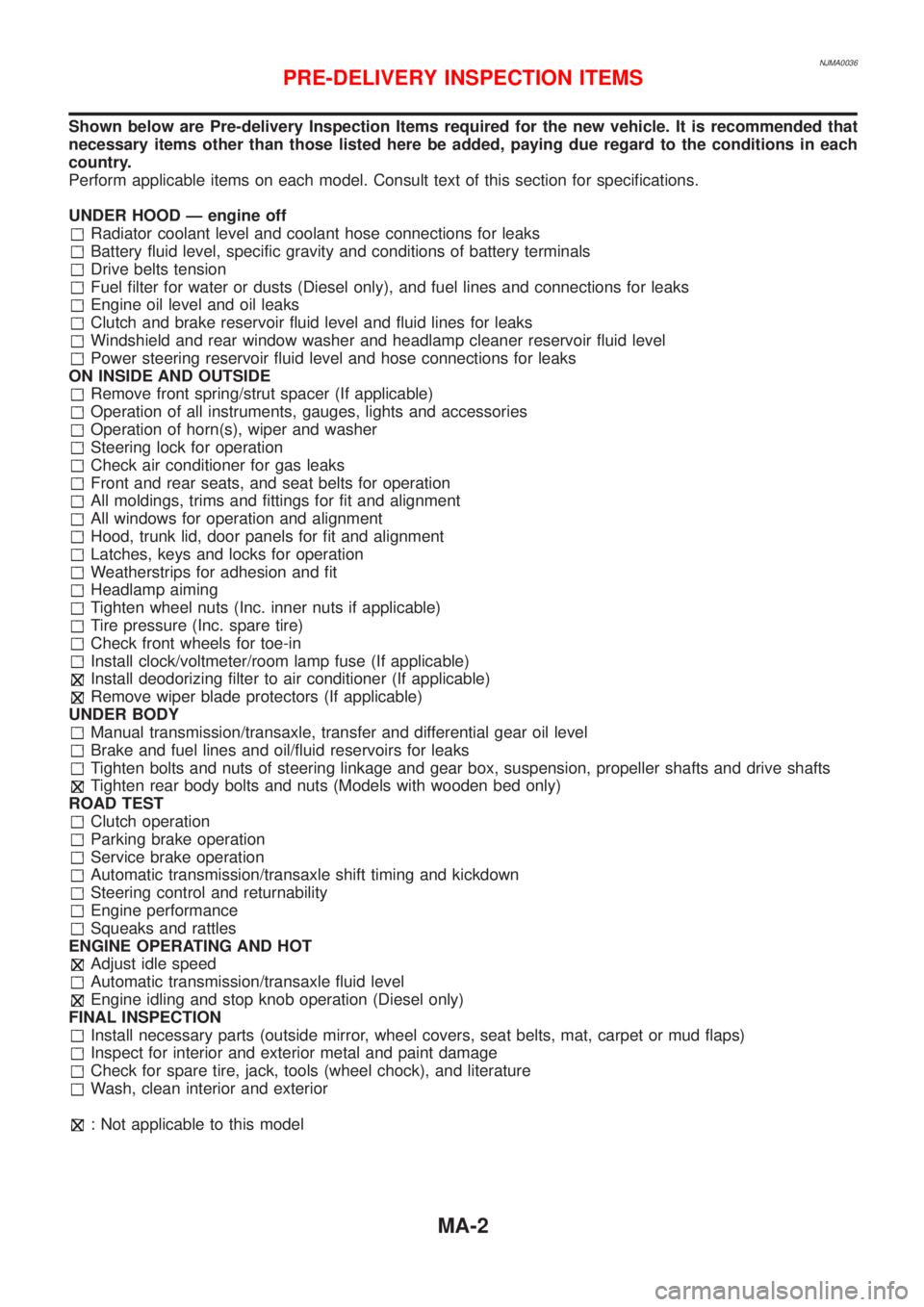
Shown below are Pre-delivery Inspection Items required for the new vehicle. It is recommended that
necessary items other than those listed here be added, paying due regard to the conditions in each
country.
Perform applicable items on each model. Consult text of this section for specifications.
UNDER HOOD Ð engine off
Radiator coolant level and coolant hose connections for leaks
Battery fluid level, specific gravity and conditions of battery terminals
Drive belts tension
Fuel filter for water or dusts (Diesel only), and fuel lines and connections for leaks
Engine oil level and oil leaks
Clutch and brake reservoir fluid level and fluid lines for leaks
Windshield and rear window washer and headlamp cleaner reservoir fluid level
Power steering reservoir fluid level and hose connections for leaks
ON INSIDE AND OUTSIDE
Remove front spring/strut spacer (If applicable)
Operation of all instruments, gauges, lights and accessories
Operation of horn(s), wiper and washer
Steering lock for operation
Check air conditioner for gas leaks
Front and rear seats, and seat belts for operation
All moldings, trims and fittings for fit and alignment
All windows for operation and alignment
Hood, trunk lid, door panels for fit and alignment
Latches, keys and locks for operation
Weatherstrips for adhesion and fit
Headlamp aiming
Tighten wheel nuts (Inc. inner nuts if applicable)
Tire pressure (Inc. spare tire)
Check front wheels for toe-in
Install clock/voltmeter/room lamp fuse (If applicable)
Install deodorizing filter to air conditioner (If applicable)
Remove wiper blade protectors (If applicable)
UNDER BODY
Manual transmission/transaxle, transfer and differential gear oil level
Brake and fuel lines and oil/fluid reservoirs for leaks
Tighten bolts and nuts of steering linkage and gear box, suspension, propeller shafts and drive shafts
Tighten rear body bolts and nuts (Models with wooden bed only)
ROAD TEST
Clutch operation
Parking brake operation
Service brake operation
Automatic transmission/transaxle shift timing and kickdown
Steering control and returnability
Engine performance
Squeaks and rattles
ENGINE OPERATING AND HOT
Adjust idle speed
Automatic transmission/transaxle fluid level
Engine idling and stop knob operation (Diesel only)
FINAL INSPECTION
Install necessary parts (outside mirror, wheel covers, seat belts, mat, carpet or mud flaps)
Inspect for interior and exterior metal and paint damage
Check for spare tire, jack, tools (wheel chock), and literature
Wash, clean interior and exterior
: Not applicable to this model
PRE-DELIVERY INSPECTION ITEMS
MA-2