2001 NISSAN ALMERA fuel type
[x] Cancel search: fuel typePage 1345 of 2898
JEF360Y
JEF361Y
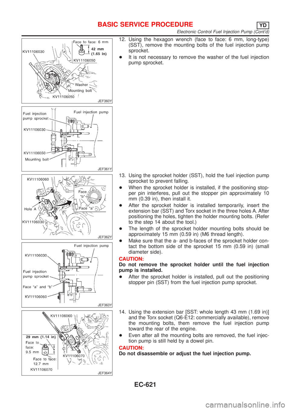
12. Using the hexagon wrench (face to face: 6 mm, long-type)
(SST), remove the mounting bolts of the fuel injection pump
sprocket.
+It is not necessary to remove the washer of the fuel injection
pump sprocket.
JEF362Y
JEF363Y
13. Using the sprocket holder (SST), hold the fuel injection pump
sprocket to prevent falling.
+When the sprocket holder is installed, if the positioning stop-
per pin interferes, pull out the stopper pin approximately 10
mm (0.39 in), then install it.
+After the sprocket holder is installed temporarily, insert the
extension bar (SST) and Torx socket in the three holes A. After
positioning the holes, tighten the holder mounting bolts. (Refer
to the step 14 about the tool.)
+The length of the sprocket holder mounting bolts should be
approximately 15 mm (0.59 in) (M6 thread length).
+Make sure that the a- and b-faces of the sprocket holder con-
tact the bottom side of the sprocket 15 mm (0.59 in) (small
diameter side).
CAUTION:
Do not remove the sprocket holder until the fuel injection
pump is installed.
+After the sprocket holder is installed, pull out the positioning
stopper pin (SST) from the fuel injection pump sprocket.
JEF364Y
14. Using the extension bar [SST: whole length 43 mm (1.69 in)]
and the Torx socket (Q6-E12: commercially available), remove
the mounting bolts, them remove the fuel injection pump
toward the rear of the engine.
+Even after all the mounting bolts are removed, the fuel injec-
tion pump is still held by a dowel pin.
CAUTION:
Do not disassemble or adjust the fuel injection pump.
BASIC SERVICE PROCEDUREYD
Electronic Control Fuel Injection Pump (Cont'd)
EC-621
Page 1347 of 2898
JEF360Y
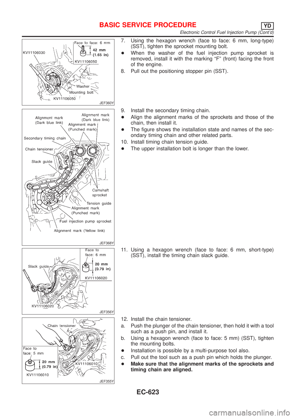
7. Using the hexagon wrench (face to face: 6 mm, long-type)
(SST), tighten the sprocket mounting bolt.
+When the washer of the fuel injection pump sprocket is
removed, install it with the marking ªFº (front) facing the front
of the engine.
8. Pull out the positioning stopper pin (SST).
JEF368Y
9. Install the secondary timing chain.
+Align the alignment marks of the sprockets and those of the
chain, then install it.
+The figure shows the installation state and names of the sec-
ondary timing chain and other related parts.
10. Install timing chain tension guide.
+The upper installation bolt is longer than the lower.
JEF356Y
11. Using a hexagon wrench (face to face: 6 mm, short-type)
(SST), install the timing chain slack guide.
JEF355Y
12. Install the chain tensioner.
a. Push the plunger of the chain tensioner, then hold it with a tool
such as a push pin, and install it.
b. Using a hexagon wrench (face to face: 5 mm) (SST), tighten
the mounting bolts.
+Installation is possible by a multi-purpose tool also.
c. Pull out the tool such as a push pin which holds the plunger.
+Make sure that the alignment marks of the sprockets and
timing chain are aligned.
BASIC SERVICE PROCEDUREYD
Electronic Control Fuel Injection Pump (Cont'd)
EC-623
Page 1752 of 2898
SEL977W
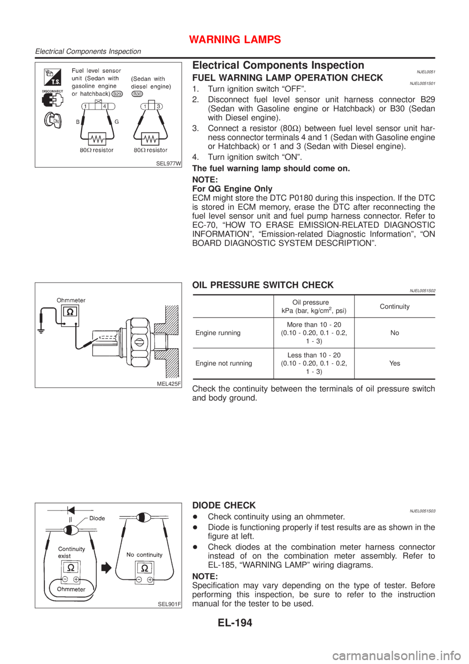
Electrical Components InspectionNJEL0051FUEL WARNING LAMP OPERATION CHECKNJEL0051S011. Turn ignition switch ªOFFº.
2. Disconnect fuel level sensor unit harness connector B29
(Sedan with Gasoline engine or Hatchback) or B30 (Sedan
with Diesel engine).
3. Connect a resistor (80W) between fuel level sensor unit har-
ness connector terminals 4 and 1 (Sedan with Gasoline engine
or Hatchback) or 1 and 3 (Sedan with Diesel engine).
4. Turn ignition switch ªONº.
The fuel warning lamp should come on.
NOTE:
For QG Engine Only
ECM might store the DTC P0180 during this inspection. If the DTC
is stored in ECM memory, erase the DTC after reconnecting the
fuel level sensor unit and fuel pump harness connector. Refer to
EC-70, ªHOW TO ERASE EMISSION-RELATED DIAGNOSTIC
INFORMATIONº, ªEmission-related Diagnostic Informationº, ªON
BOARD DIAGNOSTIC SYSTEM DESCRIPTIONº.
MEL425F
OIL PRESSURE SWITCH CHECKNJEL0051S02
Oil pressure
kPa (bar, kg/cm2, psi)Continuity
Engine runningMore than 10 - 20
(0.10 - 0.20, 0.1 - 0.2,
1-3)No
Engine not runningLess than 10 - 20
(0.10 - 0.20, 0.1 - 0.2,
1-3)Ye s
Check the continuity between the terminals of oil pressure switch
and body ground.
SEL901F
DIODE CHECKNJEL0051S03+Check continuity using an ohmmeter.
+Diode is functioning properly if test results are as shown in the
figure at left.
+Check diodes at the combination meter harness connector
instead of on the combination meter assembly. Refer to
EL-185, ªWARNING LAMPº wiring diagrams.
NOTE:
Specification may vary depending on the type of tester. Before
performing this inspection, be sure to refer to the instruction
manual for the tester to be used.
WARNING LAMPS
Electrical Components Inspection
EL-194
Page 2136 of 2898
REPLACEMENT OF CONNECTING ROD
BUSHING (SMALL END)
..........................................62
FLYWHEEL/DRIVE PLATE RUNOUT........................62
Assembly ...................................................................62
PISTON..................................................................62
CRANKSHAFT.........................................................63
SERVICE DATA AND SPECIFICATIONS (SDS).........66
General Specifications ...............................................66
Compression Pressure ..............................................66
Belt Deflection............................................................67
Spark Plug .................................................................67
Cylinder Head ............................................................67
Valve ..........................................................................68
VALVE....................................................................68
VALVE SPRING.......................................................68
VALVE LIFTER........................................................68
VALVE CLEARANCE................................................69
VALVE GUIDE.........................................................69
AVAILABLE SHIMS..................................................69
VALVE SEAT...........................................................71
VALVE SEAT RESURFACE LIMIT.............................72
Camshaft and Camshaft Bearing ..............................72
Cylinder Block ............................................................73
Piston, Piston Ring and Piston Pin ...........................74
PISTON..................................................................74
PISTON RING.........................................................74
PISTON PIN............................................................74
Connecting Rod .........................................................75
Crankshaft..................................................................75
Main Bearing..............................................................75
STANDARD.............................................................75
UNDERSIZE............................................................75
Connecting Rod Bearing ...........................................76
STANDARD SIZE....................................................76
UNDERSIZE............................................................76
Bearing Clearance .....................................................76
Miscellaneous Components.......................................76
YD
PRECAUTIONS.............................................................77
Parts Requiring Angular Tightening ...........................77
Liquid Gasket Application Procedure ........................77
PREPARATION.............................................................78
Special Service Tools ................................................78
Commercial Service Tools .........................................80
NOISE, VIBRATION AND HARSHNESS (NVH)
TROUBLESHOOTING...................................................82
NVH Troubleshooting - Engine Noise .......................82
MEASUREMENT OF COMPRESSION PRESSURE....83
DRIVE BELTS................................................................85
Inspection...................................................................85
Adjustment .................................................................85
AIR CONDITIONER COMPRESSOR BELT................86
ALTERNATOR & WATER PUMP BELT.....................86
Removal .....................................................................86
Installation ..................................................................87
AIR CLEANER...............................................................88
Changing Air Cleaner Filter .......................................88
VISCOUS PAPER TYPE...........................................88
OIL PAN.........................................................................89
Components...............................................................89
Removal .....................................................................89
Installation ..................................................................91
TIMING CHAIN..............................................................94
Secondary Timing Chain ...........................................94
REMOVAL...............................................................94
INSPECTION...........................................................96
INSTALLATION........................................................96
Primary Timing Chain ................................................99
REMOVAL.............................................................100
INSPECTION.........................................................102
INSTALLATION......................................................102
INTAKE MANIFOLD....................................................107
Removal and Installation .........................................107
PREPARATIVE WORK...........................................107
FUEL PIPING........................................................108
INTAKE MANIFOLD...............................................108
EGR VOLUME CONTROL VALVE...........................108
WATER HOSE.......................................................108
Inspection.................................................................109
INTAKE MANIFOLD...............................................109
CATALYST.................................................................. 110
Removal and Installation ......................................... 110
PREPARATIVE WORK........................................... 110
CATALYST............................................................ 110
GUSSET............................................................... 111
EXHAUST MANIFOLD, TURBOCHARGER............... 112
Removal and Installation ......................................... 112
PREPARATIVE WORK........................................... 112
EXHAUST MANIFOLD AND TURBOCHARGER....... 112
EXHAUST MANIFOLD GASKET............................. 113
Disassembly and Assembly ..................................... 113
TURBOCHARGER................................................. 113
Inspection................................................................. 114
EXHAUST MANIFOLD........................................... 114
TURBOCHARGER................................................. 114
ROCKER COVER........................................................ 117
Removal and Installation ......................................... 117
PREPARATIVE WORK........................................... 117
ROCKER COVER.................................................. 117
CYLINDER HEAD........................................................ 119
Components............................................................. 119
Removal ...................................................................120
PREPARATIVE WORK...........................................120
CAMSHAFT...........................................................120
CYLINDER HEAD..................................................121
Disassembly.............................................................121
Inspection.................................................................122
CONTENTS(Cont'd)
EM-2
Page 2237 of 2898
JEM140G
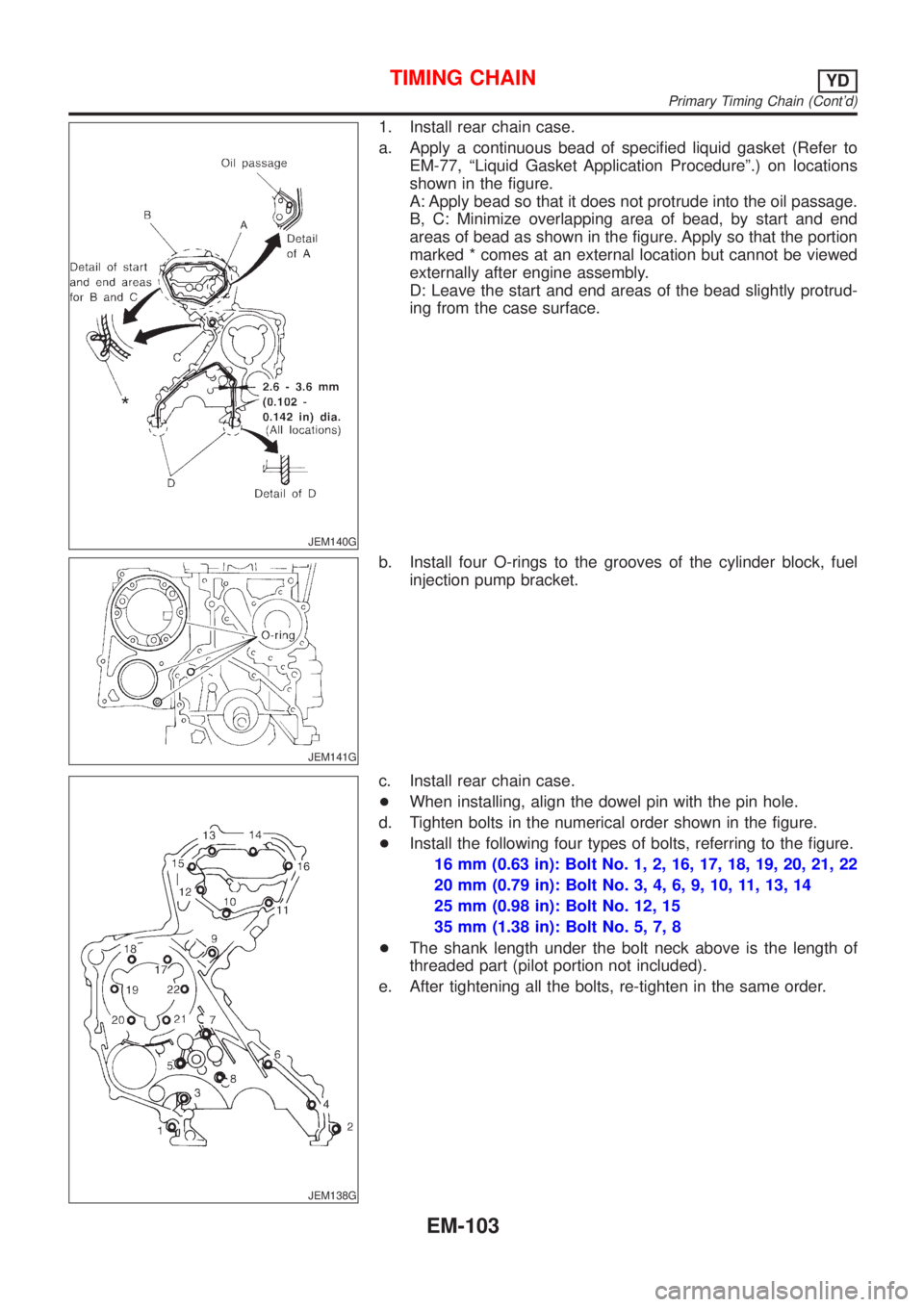
1. Install rear chain case.
a. Apply a continuous bead of specified liquid gasket (Refer to
EM-77, ªLiquid Gasket Application Procedureº.) on locations
shown in the figure.
A: Apply bead so that it does not protrude into the oil passage.
B, C: Minimize overlapping area of bead, by start and end
areas of bead as shown in the figure. Apply so that the portion
marked * comes at an external location but cannot be viewed
externally after engine assembly.
D: Leave the start and end areas of the bead slightly protrud-
ing from the case surface.
JEM141G
b. Install four O-rings to the grooves of the cylinder block, fuel
injection pump bracket.
JEM138G
c. Install rear chain case.
+When installing, align the dowel pin with the pin hole.
d. Tighten bolts in the numerical order shown in the figure.
+Install the following four types of bolts, referring to the figure.
16 mm (0.63 in): Bolt No. 1, 2, 16, 17, 18, 19, 20, 21, 22
20 mm (0.79 in): Bolt No. 3, 4, 6, 9, 10, 11, 13, 14
25 mm (0.98 in): Bolt No. 12, 15
35 mm (1.38 in): Bolt No. 5, 7, 8
+The shank length under the bolt neck above is the length of
threaded part (pilot portion not included).
e. After tightening all the bolts, re-tighten in the same order.
TIMING CHAINYD
Primary Timing Chain (Cont'd)
EM-103
Page 2354 of 2898
+Do not use gasoline, kerosine, diesel fuel, gas oil, thinners or
solvents for cleaning skin.
+If skin disorders develop, obtain medical advice without delay.
+Where practicable, degrease components prior to handling.
+Where there is a risk of eye contact, eye protection should be
worn, for example, chemical goggles or face shields; in addi-
tion an eye wash facility should be provided.
Environmental Protection PrecautionsNJGI0001S0702Burning used engine oil in small space heaters or boilers can be
recommended only for units of approved design. The heating sys-
tem must meet the requirements of HM Inspectorate of Pollution for
small burners of less than 0.4 MW. If in doubt, check with the
appropriate local authority and/or manufacturer of the approved
appliance.
Dispose of used oil and used oil filters through authorized waste
disposal contractors to licensed waste disposal sites, or to the
waste oil reclamation trade. If in doubt, contact the local authority
for advice on disposal facilities.
It is illegal to pour used oil on to the ground, down sewers or drains,
or into water courses.
The regulations concerning the pollution vary between
regions.
PRECAUTIONS FOR FUELNJGI0001S08Gasoline EngineNJGI0001S0803Models with three way catalyst
Unleaded premium gasoline of at least 95 octane (RON)
If premium gasoline is not available, unleaded regular gaso-
line with an octane rating of 91 (RON) may be temporarily
used, but only under the following precautions:
+Have the fuel tank filled only partially with unleaded regu-
lar gasoline, and fill up with premium unleaded gasoline
as soon as possible.
+Avoid full throttle driving and abrupt acceleration.
CAUTION:
Do not use leaded gasoline. Using leaded gasoline will dam-
age the three way catalyst.
Diesel Engine*:NJGI0001S0804Diesel fuel of at least 50 cetane
* If two types of diesel fuel are available, use summer or winter
fuel properly according to the following temperature conditions.
+Above þ7ÉC (20ÉF) ... Summer type diesel fuel.
+Below þ7ÉC (20ÉF) ... Winter type diesel fuel.
CAUTION:
+Do not use home heating oil, gasoline, or other alternate
fuels in your diesel engine. The use of those can cause
engine damage.
+Do not use summer fuel at temperatures below þ7ÉC
(20ÉF). The cold temperatures will cause wax to form in the
fuel. As a result, it may prevent the engine from running
smoothly.
+Do not add gasoline or other alternate fuels to diesel fuel.
PRECAUTIONS FOR AIR CONDITIONINGNJGI0001S09Use an approved refrigerant recovery unit any time the air condi-
tioning system must be discharged. Refer to HA-78, ªHFC-134a
(R-134a) Service Procedureº for specific instructions.
PRECAUTIONS
Precautions (Cont'd)
GI-8
Page 2879 of 2898
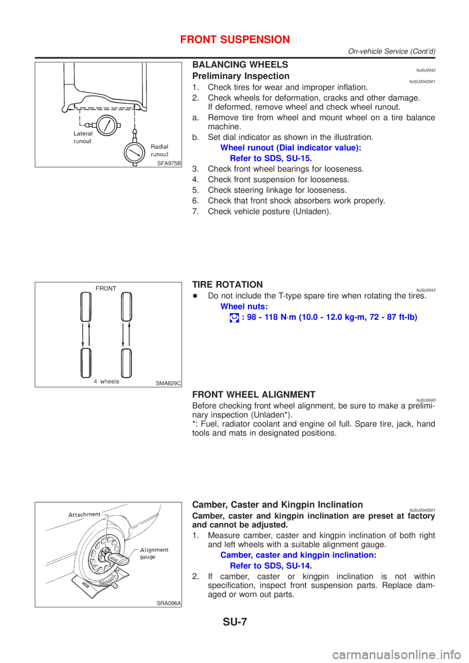
SFA975B
BALANCING WHEELSNJSU0042Preliminary InspectionNJSU0042S011. Check tires for wear and improper inflation.
2. Check wheels for deformation, cracks and other damage.
If deformed, remove wheel and check wheel runout.
a. Remove tire from wheel and mount wheel on a tire balance
machine.
b. Set dial indicator as shown in the illustration.
Wheel runout (Dial indicator value):
Refer to SDS, SU-15.
3. Check front wheel bearings for looseness.
4. Check front suspension for looseness.
5. Check steering linkage for looseness.
6. Check that front shock absorbers work properly.
7. Check vehicle posture (Unladen).
SMA829C
TIRE ROTATIONNJSU0043+Do not include the T-type spare tire when rotating the tires.
Wheel nuts:
: 98 - 118 N´m (10.0 - 12.0 kg-m, 72 - 87 ft-lb)
FRONT WHEEL ALIGNMENTNJSU0045Before checking front wheel alignment, be sure to make a prelimi-
nary inspection (Unladen*).
*: Fuel, radiator coolant and engine oil full. Spare tire, jack, hand
tools and mats in designated positions.
SRA096A
Camber, Caster and Kingpin InclinationNJSU0045S01Camber, caster and kingpin inclination are preset at factory
and cannot be adjusted.
1. Measure camber, caster and kingpin inclination of both right
and left wheels with a suitable alignment gauge.
Camber, caster and kingpin inclination:
Refer to SDS, SU-14.
2. If camber, caster or kingpin inclination is not within
specification, inspect front suspension parts. Replace dam-
aged or worn out parts.
FRONT SUSPENSION
On-vehicle Service (Cont'd)
SU-7
Page 2886 of 2898
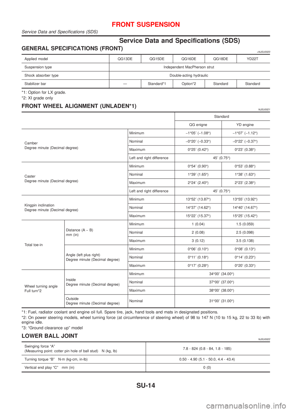
Service Data and Specifications (SDS)
GENERAL SPECIFICATIONS (FRONT)=NJSU0020
Applied model QG13DE QG15DE QG16DE QG18DE YD22T
Suspension type Independent MacPherson strut
Shock absorber type Double-acting hydraulic
Stabilizer bar Ð Standard*1 Option*2 Standard Standard
*1: Option for LX grade.
*2: XI grade only
FRONT WHEEL ALIGNMENT (UNLADEN*1)NJSU0021
Standard
QG enigne YD engine
Camber
Degree minute (Decimal degree)Minimum þ1É05¢(þ1.08É) þ1É07¢(þ1.12É)
Nominal þ0É20¢(þ0.33É) þ0É22¢(þ0.37É)
Maximum 0É25¢(0.42É) 0É23¢(0.38É)
Left and right difference 45¢(0.75É)
Caster
Degree minute (Decimal degree)Minimum 0É54¢(0.90É) 0É53¢(0.88É)
Nominal 1É39¢(1.65É) 1É38¢(1.63É)
Maximum 2É24¢(2.40É) 2É23¢(2.38É)
Left and right difference 45¢(0.75É)
Kingpin inclination
Degree minute (Decimal degree)Minimum 13É52¢(13.87É) 13É55¢(13.92É)
Nominal 14É37¢(14.62É) 14É40¢(14.67É)
Maximum 15É22¢(15.37É) 15É25¢(15.42É)
Total toe-inDistance (A þ B)
mm (in)Minimum 1 (0.04) 1.5 (0.059)
Nominal 2 (0.08) 2.5 (0.098)
Maximum 3 (0.12) 3.5 (0.138)
Angle (left plus right)
Degree minute (Decimal degree)Minimum 0É06¢(0.10É) 0É08¢(0.13É)
Nominal 0É11¢(0.18É) 0É14¢(0.23É)
Maximum 0É17¢(0.28É) 0É20¢(0.33É)
Wheel turning angle
Full turn*2Inside
Degree minute (Decimal degree)Minimum 34É00¢(34.00É)
Nominal 37É00¢(37.00É)
Maximum 38É00¢(38.00É)
Outside
Degree minute (Decimal degree)Nominal 31É00¢(31.00É)
*1: Fuel, radiator coolant and engine oil full. Spare tire, jack, hand tools and mats in designated positions.
*2: On power steering models, wheel turning force (at circumference of steering wheel) of 98 to 147 N (10 to 15 kg, 22 to 33 lb) with
engine idle.
*3: ªGround clearance upº model
LOWER BALL JOINTNJSU0022
Swinging force ªAº
(Measuring point: cotter pin hole of ball stud) N (kg, lb)7.8 - 824 (0.8 - 84, 1.8 - 185)
Turning torque ªBº N´m (kg-cm, in-lb) 0.50 - 4.90 (5.1 - 50.0, 4.4 - 43.4)
Vertical end play ªCº mm (in)0 (0)
FRONT SUSPENSION
Service Data and Specifications (SDS)
SU-14