Page 1472 of 2898
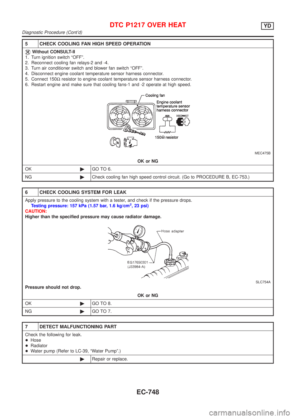
5 CHECK COOLING FAN HIGH SPEED OPERATION
Without CONSULT-II
1. Turn ignition switch ªOFFº.
2. Reconnect cooling fan relays-2 and -4.
3. Turn air conditioner switch and blower fan switch ªOFFº.
4. Disconnect engine coolant temperature sensor harness connector.
5. Connect 150Wresistor to engine coolant temperature sensor harness connector.
6. Restart engine and make sure that cooling fans-1 and -2 operate at high speed.
MEC475B
OK or NG
OK©GO TO 6.
NG©Check cooling fan high speed control circuit. (Go to PROCEDURE B, EC-753.)
6 CHECK COOLING SYSTEM FOR LEAK
Apply pressure to the cooling system with a tester, and check if the pressure drops.
Testing pressure: 157 kPa (1.57 bar, 1.6 kg/cm2, 23 psi)
CAUTION:
Higher than the specified pressure may cause radiator damage.
SLC754A
Pressure should not drop.
OK or NG
OK©GO TO 8.
NG©GO TO 7.
7 DETECT MALFUNCTIONING PART
Check the following for leak.
+Hose
+Radiator
+Water pump (Refer to LC-39, ªWater Pumpº.)
©Repair or replace.
DTC P1217 OVER HEATYD
Diagnostic Procedure (Cont'd)
EC-748
Page 1480 of 2898
9 CHECK INTERMITTENT INCIDENT
1. Perform ªTROUBLE DIAGNOSIS FOR INTERMITTENT INCIDENTº, EC-665.
©INSPECTION END
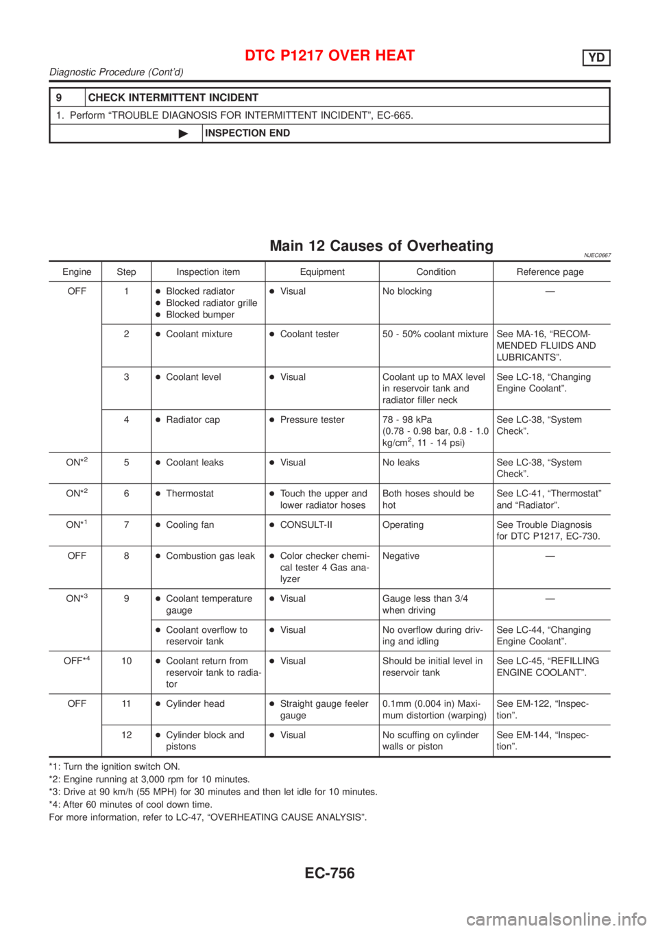
Main 12 Causes of OverheatingNJEC0667
Engine Step Inspection item Equipment Condition Reference page
OFF 1+Blocked radiator
+Blocked radiator grille
+Blocked bumper+Visual No blocking Ð
2+Coolant mixture+Coolant tester 50 - 50% coolant mixture See MA-16, ªRECOM-
MENDED FLUIDS AND
LUBRICANTSº.
3+Coolant level+Visual Coolant up to MAX level
in reservoir tank and
radiator filler neckSee LC-18, ªChanging
Engine Coolantº.
4+Radiator cap+Pressure tester 78 - 98 kPa
(0.78 - 0.98 bar, 0.8 - 1.0
kg/cm
2, 11 - 14 psi)See LC-38, ªSystem
Checkº.
ON*
25+Coolant leaks+Visual No leaks See LC-38, ªSystem
Checkº.
ON*
26+Thermostat+Touch the upper and
lower radiator hosesBoth hoses should be
hotSee LC-41, ªThermostatº
and ªRadiatorº.
ON*
17+Cooling fan+CONSULT-II Operating See Trouble Diagnosis
for DTC P1217, EC-730.
OFF 8+Combustion gas leak+Color checker chemi-
cal tester 4 Gas ana-
lyzerNegative Ð
ON*
39+Coolant temperature
gauge+Visual Gauge less than 3/4
when drivingÐ
+Coolant overflow to
reservoir tank+Visual No overflow during driv-
ing and idlingSee LC-44, ªChanging
Engine Coolantº.
OFF*
410+Coolant return from
reservoir tank to radia-
tor+Visual Should be initial level in
reservoir tankSee LC-45, ªREFILLING
ENGINE COOLANTº.
OFF 11+Cylinder head+Straight gauge feeler
gauge0.1mm (0.004 in) Maxi-
mum distortion (warping)See EM-122, ªInspec-
tionº.
12+Cylinder block and
pistons+Visual No scuffing on cylinder
walls or pistonSee EM-144, ªInspec-
tionº.
*1: Turn the ignition switch ON.
*2: Engine running at 3,000 rpm for 10 minutes.
*3: Drive at 90 km/h (55 MPH) for 30 minutes and then let idle for 10 minutes.
*4: After 60 minutes of cool down time.
For more information, refer to LC-47, ªOVERHEATING CAUSE ANALYSISº.
DTC P1217 OVER HEATYD
Diagnostic Procedure (Cont'd)
EC-756
Page 1482 of 2898
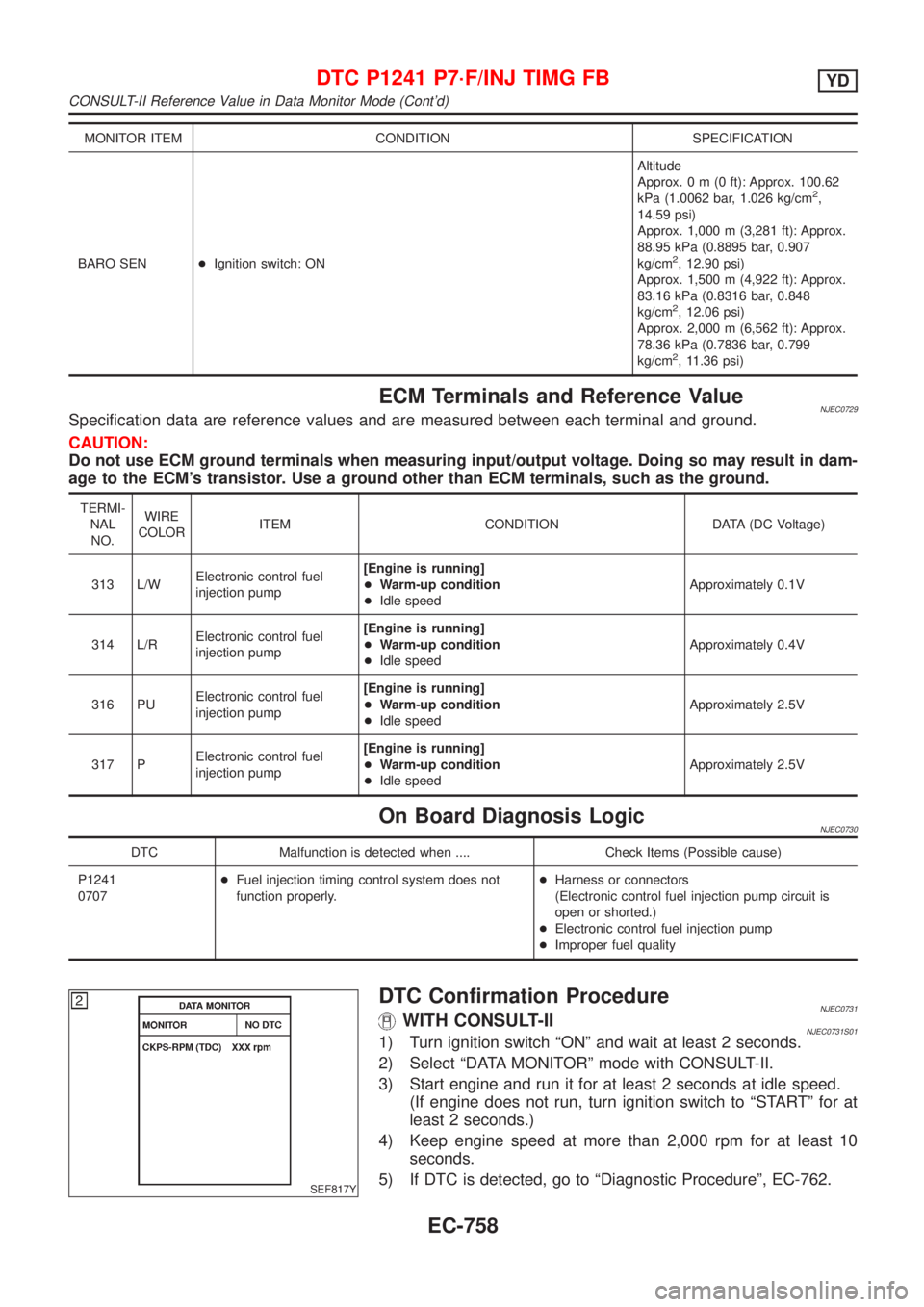
MONITOR ITEM CONDITION SPECIFICATION
BARO SEN+Ignition switch: ONAltitude
Approx.0m(0ft): Approx. 100.62
kPa (1.0062 bar, 1.026 kg/cm
2,
14.59 psi)
Approx. 1,000 m (3,281 ft): Approx.
88.95 kPa (0.8895 bar, 0.907
kg/cm
2, 12.90 psi)
Approx. 1,500 m (4,922 ft): Approx.
83.16 kPa (0.8316 bar, 0.848
kg/cm
2, 12.06 psi)
Approx. 2,000 m (6,562 ft): Approx.
78.36 kPa (0.7836 bar, 0.799
kg/cm
2, 11.36 psi)
ECM Terminals and Reference ValueNJEC0729Specification data are reference values and are measured between each terminal and ground.
CAUTION:
Do not use ECM ground terminals when measuring input/output voltage. Doing so may result in dam-
age to the ECM's transistor. Use a ground other than ECM terminals, such as the ground.
TERMI-
NAL
NO.WIRE
COLORITEM CONDITION DATA (DC Voltage)
313 L/WElectronic control fuel
injection pump[Engine is running]
+Warm-up condition
+Idle speedApproximately 0.1V
314 L/RElectronic control fuel
injection pump[Engine is running]
+Warm-up condition
+Idle speedApproximately 0.4V
316 PUElectronic control fuel
injection pump[Engine is running]
+Warm-up condition
+Idle speedApproximately 2.5V
317 PElectronic control fuel
injection pump[Engine is running]
+Warm-up condition
+Idle speedApproximately 2.5V
On Board Diagnosis LogicNJEC0730
DTC Malfunction is detected when .... Check Items (Possible cause)
P1241
0707+Fuel injection timing control system does not
function properly.+Harness or connectors
(Electronic control fuel injection pump circuit is
open or shorted.)
+Electronic control fuel injection pump
+Improper fuel quality
SEF817Y
DTC Confirmation ProcedureNJEC0731WITH CONSULT-IINJEC0731S011) Turn ignition switch ªONº and wait at least 2 seconds.
2) Select ªDATA MONITORº mode with CONSULT-II.
3) Start engine and run it for at least 2 seconds at idle speed.
(If engine does not run, turn ignition switch to ªSTARTº for at
least 2 seconds.)
4) Keep engine speed at more than 2,000 rpm for at least 10
seconds.
5) If DTC is detected, go to ªDiagnostic Procedureº, EC-762.
DTC P1241 P7´F/INJ TIMG FBYD
CONSULT-II Reference Value in Data Monitor Mode (Cont'd)
EC-758
Page 1525 of 2898
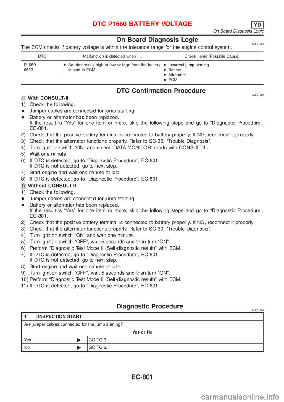
On Board Diagnosis LogicNJEC1258The ECM checks if battery voltage is within the tolerance range for the engine control system.
DTC Malfunction is detected when ... Check Items (Possible Cause)
P1660
0502+An abnormally high or low voltage from the battery
is sent to ECM.+Incorrect jump starting
+Battery
+Alternator
+ECM
DTC Confirmation ProcedureNJEC1259With CONSULT-II
1) Check the following.
+Jumper cables are connected for jump starting.
+Battery or alternator has been replaced.
If the result is ªYesº for one item or more, skip the following steps and go to ªDiagnostic Procedureº,
EC-801.
2) Check that the positive battery terminal is connected to battery properly. If NG, reconnect it properly.
3) Check that the alternator functions properly. Refer to SC-30, ªTrouble Diagnosisº.
4) Turn ignition switch ªONº and select ªDATA MONITORº mode with CONSULT-II.
5) Wait one minute.
6) If DTC is detected, go to ªDiagnostic Procedureº, EC-801.
If DTC is not detected, go to next step.
7) Start engine and wait one minute at idle.
8) If DTC is detected, go to ªDiagnostic Procedureº, EC-801.
Without CONSULT-II
1) Check the following.
+Jumper cables are connected for jump starting.
+Battery or alternator has been replaced.
If the result is ªYesº for one item or more, skip the following steps and go to ªDiagnostic Procedureº,
EC-801.
2) Check that the positive battery terminal is connected to battery properly. If NG, reconnect it properly.
3) Check that the alternator functions properly. Refer to SC-30, ªTrouble Diagnosisº.
4) Turn ignition switch ªONº and wait one minute.
5) Turn ignition switch ªOFFº, wait 5 seconds and then turn ªONº.
6) Perform ªDiagnostic Test Mode II (Self-diagnostic result)º with ECM.
7) If DTC is detected, go to ªDiagnostic Procedureº, EC-801.
If DTC is not detected, go to next step.
8) Start engine and wait one minute at idle.
9) Turn ignition switch ªOFFº, wait 5 seconds and then turn ªONº.
10) Perform ªDiagnostic Test Mode II (Self-diagnostic result)º with ECM.
11) If DTC is detected, go to ªDiagnostic Procedureº, EC-801.
Diagnostic ProcedureNJEC1260
1 INSPECTION START
Are jumper cables connected for the jump starting?
YesorNo
Ye s©GO TO 3.
No©GO TO 2.
DTC P1660 BATTERY VOLTAGEYD
On Board Diagnosis Logic
EC-801
Page 1530 of 2898
DescriptionNJEC0760SYSTEM DESCRIPTIONNJEC0760S01
Sensor Input Signal to ECMECM
Func-
tionActuator
Crankshaft position sensor
(TDC)Engine speed
Glow
controlGlow lamp,
Glow relay
¯
Glow plugs Engine coolant tempera-
ture sensorEngine coolant tem-
perature
When engine coolant temperature is more than approximately
75ÉC (167ÉF), the glow relay turns off.
When coolant temperature is lower than approximately 75ÉC
(167ÉF):
+Ignition switch ON
After ignition switch has turned to ON, the glow relay turns ON
for a certain period of time in relation to engine coolant
temperature, allowing current to flow through glow plug.
+Cranking
The glow relay turns ON, allowing current to flow through glow
plug.
+Starting
After engine has started, current continues to flow through
glow plug (after-glow mode) for a certain period in relation to
engine coolant temperature.
The glow indicator lamp turns ON for a certain period of time in
relation to engine cooalnt temperature at the time glow relay is
turned ON.
SEF376Y
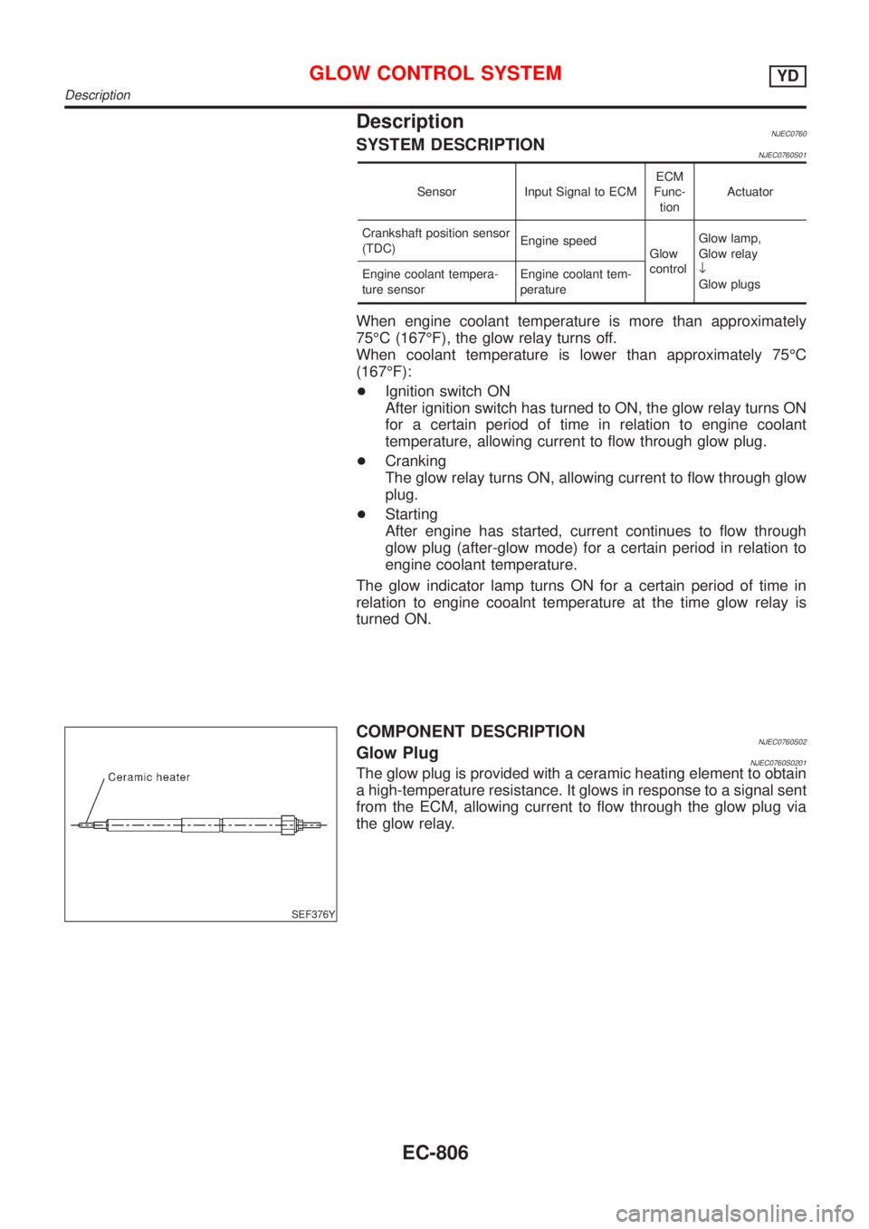
COMPONENT DESCRIPTIONNJEC0760S02Glow PlugNJEC0760S0201The glow plug is provided with a ceramic heating element to obtain
a high-temperature resistance. It glows in response to a signal sent
from the ECM, allowing current to flow through the glow plug via
the glow relay.
GLOW CONTROL SYSTEMYD
Description
EC-806
Page 1531 of 2898
ECM Terminals and Reference ValueNJEC0761Specification data are reference values and are measured between each terminal and ground.
CAUTION:
Do not use ECM ground terminals when measuring input/output voltage. Doing so may result in dam-
age to the ECM's transistor. Use a ground other than ECM terminals, such as the ground.
TERMI-
NAL
NO.WIRE
COLORITEM CONDITION DATA (DC Voltage)
214 W/B Glow relay Refer to ªSYSTEM DESCRIPTIONº, EC-806.
508 OR Glow indicator lamp[Ignition switch ªONº]
+Glow indicator lamp is ªONºApproximately 1V
[Ignition switch ªONº]
+Glow indicator lamp is ªOFFºBATTERY VOLTAGE
(11 - 14V)
GLOW CONTROL SYSTEMYD
ECM Terminals and Reference Value
EC-807
Page 1533 of 2898
Diagnostic ProcedureNJEC0763
1 INSPECTION START
Check fuel level, fuel supplying system, starter motor, etc.
OK or NG
OK©GO TO 2.
NG©Correct.
2 CHECK INSTALLATION
Check that glow plug nut and all glow plug connecting plate nuts are installed properly.
SEF392YA
OK or NG
OK (With CONSULT-II)©GO TO 3.
OK (Without CONSULT-
II)©GO TO 4.
NG©Install properly.
3 CHECK GLOW INDICATOR LAMP OPERATION
With CONSULT-II
1. Turn ignition switch ªONº.
2. Select ªCOOLAN TEMP/Sº in ªDATA MONITORº mode with CONSULT-II.
3. Confirm that ªCOOLAN TEMP/Sº indicates below 75ÉC (167ÉF). If it indicates above 75ÉC (167ÉF), cool down engine.
SEF013Y
4. Turn ignition switch ªOFFº, wait at least 5 seconds and then turn ªONº.
5. Make sure that glow indicator lamp is turned ªONº for 1.5 seconds or more after turning ignition switch ªONº, and then
turned ªOFFº.
OK or NG
OK©GO TO 5.
NG©GO TO 6.
GLOW CONTROL SYSTEMYD
Diagnostic Procedure
EC-809
Page 1534 of 2898
4 CHECK GLOW INDICATOR LAMP OPERATION
Without CONSULT-II
1. Turn ignition switch ªONº.
2. Confirm that the voltage between ECM terminal 347 (Engine coolant temperature sensor signal) and ground is above
1.36V. If it is below 1.36V, cool down engine.
SEF442Z
3. Turn ignition switch ªOFFº, wait at least 5 seconds and then turn ªONº.
4. Make sure that glow indicator lamp is turned ªONº for 1.5 seconds or more after turning ignition switch ªONº, and then
turned ªOFFº.
OK or NG
OK©GO TO 5.
NG©GO TO 6.
5 CHECK GLOW CONTROL SYSTEM OVERALL FUNCTION
1. Turn ignition switch ªOFFº.
2. Set voltmeter probe between glow plug and engine body.
3. Turn ignition switch ªONº.
4. Check the voltage between glow plug and engine body under the following conditions.
SEF431Y
OK or NG
OK©INSPECTION END
NG©GO TO 11.
GLOW CONTROL SYSTEMYD
Diagnostic Procedure (Cont'd)
EC-810