2001 NISSAN ALMERA coolant
[x] Cancel search: coolantPage 2396 of 2898
NJGI0011
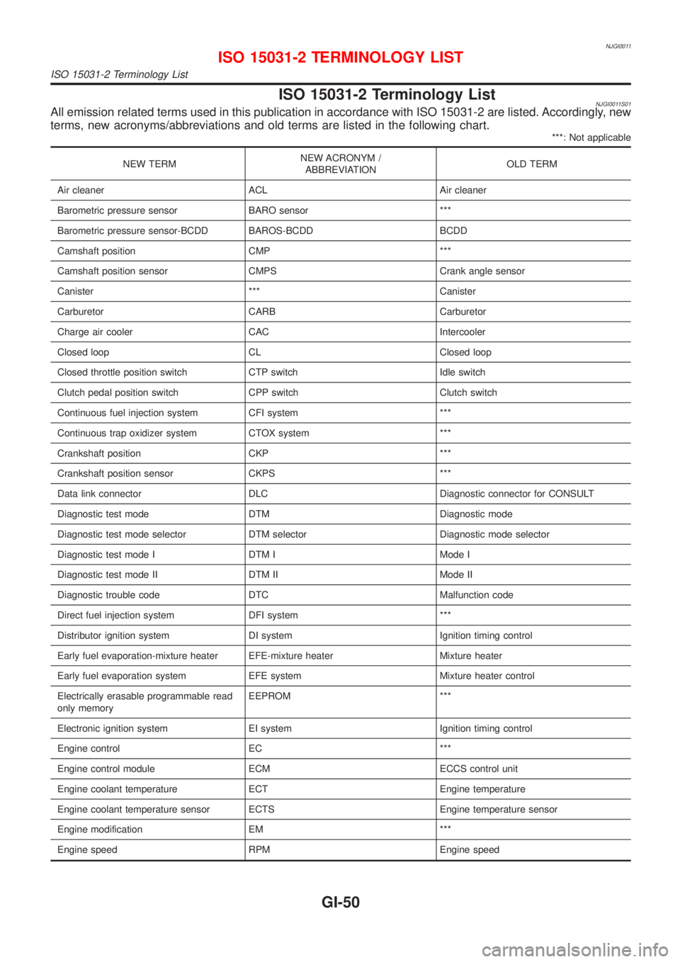
ISO 15031-2 Terminology ListNJGI0011S01All emission related terms used in this publication in accordance with ISO 15031-2 are listed. Accordingly, new
terms, new acronyms/abbreviations and old terms are listed in the following chart.
***: Not applicable
NEW TERMNEW ACRONYM /
ABBREVIATIONOLD TERM
Air cleaner ACL Air cleaner
Barometric pressure sensor BARO sensor ***
Barometric pressure sensor-BCDD BAROS-BCDD BCDD
Camshaft position CMP ***
Camshaft position sensor CMPS Crank angle sensor
Canister *** Canister
Carburetor CARB Carburetor
Charge air cooler CAC Intercooler
Closed loop CL Closed loop
Closed throttle position switch CTP switch Idle switch
Clutch pedal position switch CPP switch Clutch switch
Continuous fuel injection system CFI system ***
Continuous trap oxidizer system CTOX system ***
Crankshaft position CKP ***
Crankshaft position sensor CKPS ***
Data link connector DLC Diagnostic connector for CONSULT
Diagnostic test mode DTM Diagnostic mode
Diagnostic test mode selector DTM selector Diagnostic mode selector
Diagnostic test mode I DTM I Mode I
Diagnostic test mode II DTM II Mode II
Diagnostic trouble code DTC Malfunction code
Direct fuel injection system DFI system ***
Distributor ignition system DI system Ignition timing control
Early fuel evaporation-mixture heater EFE-mixture heater Mixture heater
Early fuel evaporation system EFE system Mixture heater control
Electrically erasable programmable read
only memoryEEPROM ***
Electronic ignition system EI system Ignition timing control
Engine control EC ***
Engine control module ECM ECCS control unit
Engine coolant temperature ECT Engine temperature
Engine coolant temperature sensor ECTS Engine temperature sensor
Engine modification EM ***
Engine speed RPM Engine speed
ISO 15031-2 TERMINOLOGY LIST
ISO 15031-2 Terminology List
GI-50
Page 2488 of 2898
Heater & Cooling Unit (Heater Core)
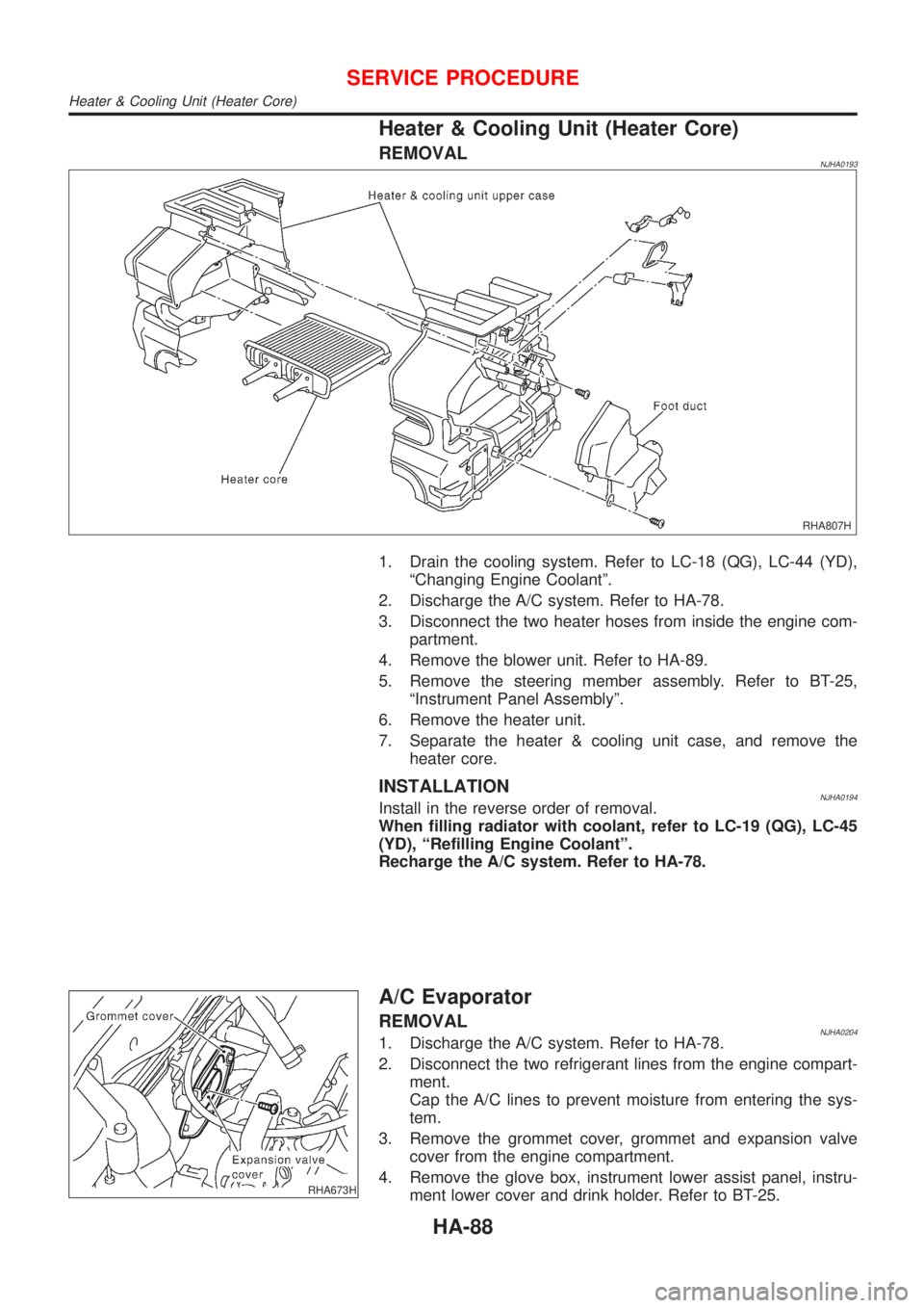
REMOVALNJHA0193
RHA807H
1. Drain the cooling system. Refer to LC-18 (QG), LC-44 (YD),
ªChanging Engine Coolantº.
2. Discharge the A/C system. Refer to HA-78.
3. Disconnect the two heater hoses from inside the engine com-
partment.
4. Remove the blower unit. Refer to HA-89.
5. Remove the steering member assembly. Refer to BT-25,
ªInstrument Panel Assemblyº.
6. Remove the heater unit.
7. Separate the heater & cooling unit case, and remove the
heater core.
INSTALLATIONNJHA0194Install in the reverse order of removal.
When filling radiator with coolant, refer to LC-19 (QG), LC-45
(YD), ªRefilling Engine Coolantº.
Recharge the A/C system. Refer to HA-78.
RHA673H
A/C Evaporator
REMOVALNJHA02041. Discharge the A/C system. Refer to HA-78.
2. Disconnect the two refrigerant lines from the engine compart-
ment.
Cap the A/C lines to prevent moisture from entering the sys-
tem.
3. Remove the grommet cover, grommet and expansion valve
cover from the engine compartment.
4. Remove the glove box, instrument lower assist panel, instru-
ment lower cover and drink holder. Refer to BT-25.
SERVICE PROCEDURE
Heater & Cooling Unit (Heater Core)
HA-88
Page 2501 of 2898
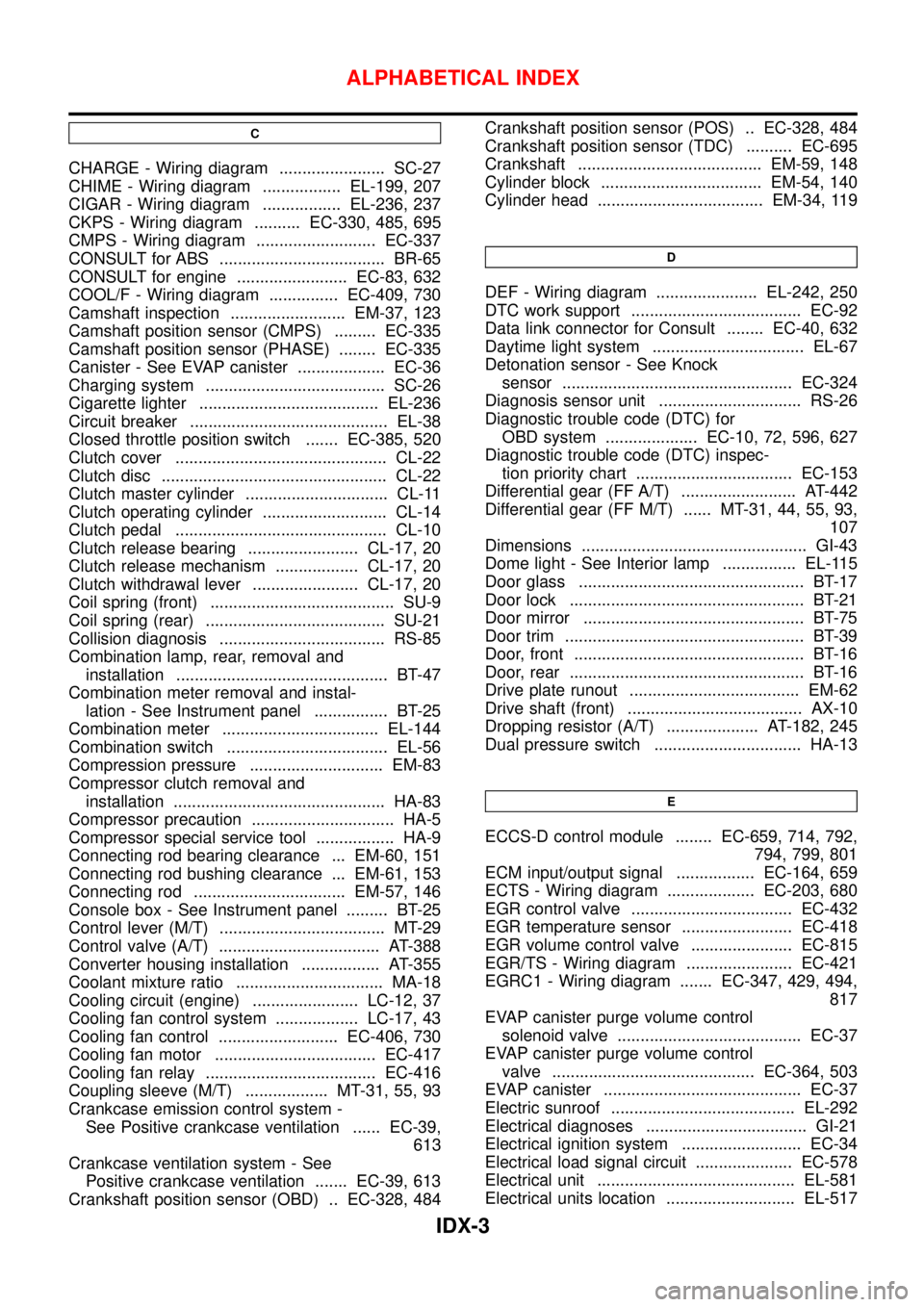
C
CHARGE - Wiring diagram ....................... SC-27
CHIME - Wiring diagram ................. EL-199, 207
CIGAR - Wiring diagram ................. EL-236, 237
CKPS - Wiring diagram .......... EC-330, 485, 695
CMPS - Wiring diagram .......................... EC-337
CONSULT for ABS .................................... BR-65
CONSULT for engine ........................ EC-83, 632
COOL/F - Wiring diagram ............... EC-409, 730
Camshaft inspection ......................... EM-37, 123
Camshaft position sensor (CMPS) ......... EC-335
Camshaft position sensor (PHASE) ........ EC-335
Canister - See EVAP canister ................... EC-36
Charging system ....................................... SC-26
Cigarette lighter ....................................... EL-236
Circuit breaker ........................................... EL-38
Closed throttle position switch ....... EC-385, 520
Clutch cover .............................................. CL-22
Clutch disc ................................................. CL-22
Clutch master cylinder ............................... CL-11
Clutch operating cylinder ........................... CL-14
Clutch pedal .............................................. CL-10
Clutch release bearing ........................ CL-17, 20
Clutch release mechanism .................. CL-17, 20
Clutch withdrawal lever ....................... CL-17, 20
Coil spring (front) ........................................ SU-9
Coil spring (rear) ....................................... SU-21
Collision diagnosis .................................... RS-85
Combination lamp, rear, removal and
installation .............................................. BT-47
Combination meter removal and instal-
lation - See Instrument panel ................ BT-25
Combination meter .................................. EL-144
Combination switch ................................... EL-56
Compression pressure ............................. EM-83
Compressor clutch removal and
installation .............................................. HA-83
Compressor precaution ............................... HA-5
Compressor special service tool ................. HA-9
Connecting rod bearing clearance ... EM-60, 151
Connecting rod bushing clearance ... EM-61, 153
Connecting rod ................................. EM-57, 146
Console box - See Instrument panel ......... BT-25
Control lever (M/T) .................................... MT-29
Control valve (A/T) ................................... AT-388
Converter housing installation ................. AT-355
Coolant mixture ratio ................................ MA-18
Cooling circuit (engine) ....................... LC-12, 37
Cooling fan control system .................. LC-17, 43
Cooling fan control .......................... EC-406, 730
Cooling fan motor ................................... EC-417
Cooling fan relay ..................................... EC-416
Coupling sleeve (M/T) .................. MT-31, 55, 93
Crankcase emission control system -
See Positive crankcase ventilation ...... EC-39,
613
Crankcase ventilation system - See
Positive crankcase ventilation ....... EC-39, 613
Crankshaft position sensor (OBD) .. EC-328, 484Crankshaft position sensor (POS) .. EC-328, 484
Crankshaft position sensor (TDC) .......... EC-695
Crankshaft ........................................ EM-59, 148
Cylinder block ................................... EM-54, 140
Cylinder head .................................... EM-34, 119
D
DEF - Wiring diagram ...................... EL-242, 250
DTC work support ..................................... EC-92
Data link connector for Consult ........ EC-40, 632
Daytime light system ................................. EL-67
Detonation sensor - See Knock
sensor .................................................. EC-324
Diagnosis sensor unit ............................... RS-26
Diagnostic trouble code (DTC) for
OBD system .................... EC-10, 72, 596, 627
Diagnostic trouble code (DTC) inspec-
tion priority chart .................................. EC-153
Differential gear (FF A/T) ......................... AT-442
Differential gear (FF M/T) ...... MT-31, 44, 55, 93,
107
Dimensions ................................................. GI-43
Dome light - See Interior lamp ................ EL-115
Door glass ................................................. BT-17
Door lock ................................................... BT-21
Door mirror ................................................ BT-75
Door trim .................................................... BT-39
Door, front .................................................. BT-16
Door, rear ................................................... BT-16
Drive plate runout ..................................... EM-62
Drive shaft (front) ...................................... AX-10
Dropping resistor (A/T) .................... AT-182, 245
Dual pressure switch ................................ HA-13
E
ECCS-D control module ........ EC-659, 714, 792,
794, 799, 801
ECM input/output signal ................. EC-164, 659
ECTS - Wiring diagram ................... EC-203, 680
EGR control valve ................................... EC-432
EGR temperature sensor ........................ EC-418
EGR volume control valve ...................... EC-815
EGR/TS - Wiring diagram ....................... EC-421
EGRC1 - Wiring diagram ....... EC-347, 429, 494,
817
EVAP canister purge volume control
solenoid valve ........................................ EC-37
EVAP canister purge volume control
valve ............................................ EC-364, 503
EVAP canister ........................................... EC-37
Electric sunroof ........................................ EL-292
Electrical diagnoses ................................... GI-21
Electrical ignition system .......................... EC-34
Electrical load signal circuit ..................... EC-578
Electrical unit ........................................... EL-581
Electrical units location ............................ EL-517
ALPHABETICAL INDEX
IDX-3
Page 2502 of 2898
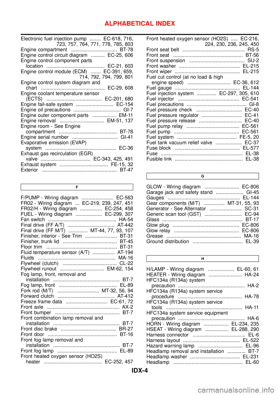
Electronic fuel injection pump ........ EC-618, 716,
723, 757, 764, 771, 778, 785, 803
Engine compartment ................................. BT-78
Engine control circuit diagram .......... EC-25, 606
Engine control component parts
location .......................................... EC-21, 603
Engine control module (ECM) ....... EC-391, 659,
714, 792, 794, 799, 801
Engine control system diagram and
chart .............................................. EC-29, 608
Engine coolant temperature sensor
(ECTS) ........................................ EC-201, 680
Engine fail-safe system ........................... EC-154
Engine oil precautions .................................. GI-7
Engine outer component parts ................. EM-11
Engine removal ................................ EM-51, 137
Engine room - See Engine
compartment .......................................... BT-78
Engine serial number ................................. GI-41
Evaporative emission (EVAP)
system ................................................... EC-36
Exhaust gas recirculation (EGR)
valve .................................... EC-343, 425, 491
Exhaust system ................................... FE-15, 32
Exterior ...................................................... BT-47
F
F/PUMP - Wiring diagram ....................... EC-563
FR02 - Wiring diagram ... EC-219, 239, 247, 451
FR02/H - Wiring diagram ................ EC-254, 458
FUEL - Wiring diagram ................... EC-299, 307
Fan switch ................................................. HA-54
Final drive (FF A/T) .................................. AT-442
Final drive (FF M/T) .............. MT-44, 77, 93, 107
Finisher, interior - See Trim ....................... BT-31
Finisher, trunk lid ....................................... BT-45
Floor trim ................................................... BT-31
Fluid temperature sensor (A/T) ................ AT-194
Fluids ........................................................ MA-16
Flywheel (clutch) ....................................... CL-22
Flywheel runout ................................ EM-62, 154
Fog lamp, front, removal and
installation ................................................ BT-7
Fog lamp, front .......................................... EL-89
Fork rod (M/T) .............................. MT-32, 56, 94
Forward clutch ......................................... AT-412
Freeze frame data .............................. EC-61, 72
Front axle .................................................... AX-2
Front bumper ............................................... BT-7
Front combination lamp removal and
installation ................................................ BT-7
Front disc brake ........................................ BR-27
Front door .................................................. BT-16
Front fog lamp removal and
installation ................................................ BT-7
Front fog lamp ........................................... EL-89
Front heated oxygen sensor (HO2S)
heater .......................................... EC-252, 457Front heated oxygen sensor (HO2S) ..... EC-216,
224, 230, 236, 245, 450
Front seat belt ............................................. RS-5
Front seat .................................................. BT-56
Front suspension ........................................ SU-2
Front washer ............................................ EL-215
Front wiper ............................................... EL-215
Fuel cut control (at no load & high
engine speed) ............................... EC-36, 612
Fuel gauge ............................................... EL-144
Fuel injection system .............. EC-297, 305, 610
Fuel injector ............................................ EC-541
Fuel precautions ........................................... GI-8
Fuel pressure check ................................. EC-40
Fuel pressure regulator ............................. EC-41
Fuel pressure release ............................... EC-40
Fuel pump relay ...................................... EC-561
Fuel pump ............................................... EC-561
Fuel system ........................................... FE-5, 20
Fuel tank vacuum relief valve ................... EC-37
Fuse block ............................................... EL-577
Fuse ........................................................... EL-38
Fusible link ................................................. EL-38
G
GLOW - Wiring diagram ......................... EC-806
Garage jack and safety stand .................... GI-45
Gauges .................................................... EL-144
Gear components (M/T) ............... MT-31, 55, 93
Generator - See Alternator ....................... SC-31
Generic scan tool (GST) ........................... EC-94
Glass .......................................................... BT-17
Glow plug ................................................ EC-806
Glow relay ............................................... EC-806
Grease ...................................................... MA-16
Ground distribution .................................... EL-39
H
H/LAMP - Wiring diagram ................... EL-60, 61
HEATER - Wiring diagram ........................ HA-24
HFC134a (R134a) system
precaution ................................................ HA-2
HFC134a (R134a) system service
procedure .............................................. HA-78
HFC134a (R134a) system service
tools ....................................................... HA-11
HFC134a system service equipment
precaution ................................................ HA-6
HORN - Wiring diagram .................. EL-234, 235
HSEAT - Wiring diagram ................. EL-288, 290
Harness connector ...................................... EL-6
Harness layout ......................................... EL-522
Hazard warning lamp ................................ EL-96
Headlamp removal and installation ............. BT-7
Headlamp washer .................................... EL-231
Headlamp .................................................. EL-60
ALPHABETICAL INDEX
IDX-4
Page 2507 of 2898
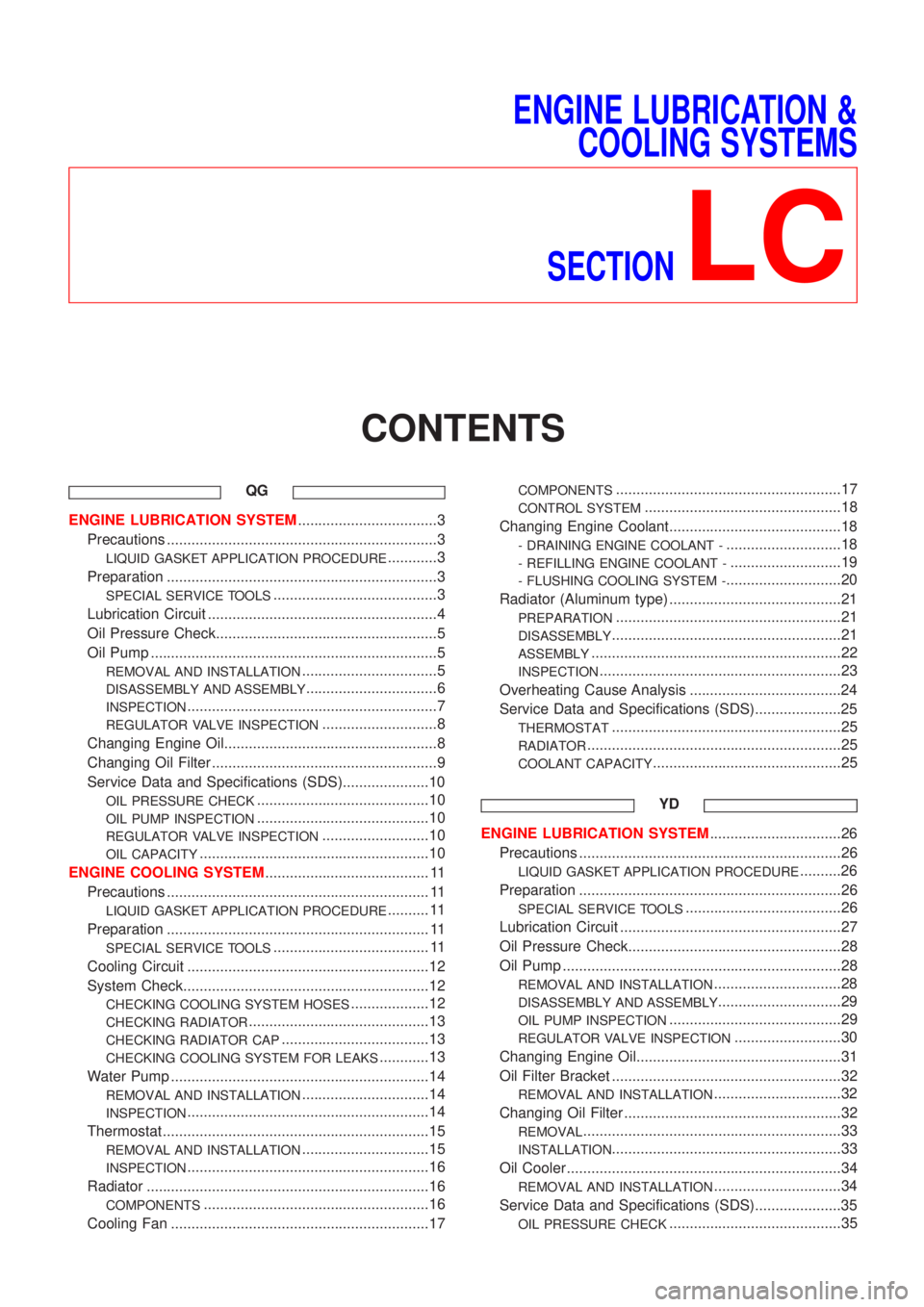
ENGINE LUBRICATION &
COOLING SYSTEMS
SECTION
LC
CONTENTS
QG
ENGINE LUBRICATION SYSTEM..................................3
Precautions ..................................................................3
LIQUID GASKET APPLICATION PROCEDURE............3
Preparation ..................................................................3
SPECIAL SERVICE TOOLS........................................3
Lubrication Circuit ........................................................4
Oil Pressure Check......................................................5
Oil Pump ......................................................................5
REMOVAL AND INSTALLATION.................................5
DISASSEMBLY AND ASSEMBLY................................6
INSPECTION.............................................................7
REGULATOR VALVE INSPECTION............................8
Changing Engine Oil....................................................8
Changing Oil Filter .......................................................9
Service Data and Specifications (SDS).....................10
OIL PRESSURE CHECK..........................................10
OIL PUMP INSPECTION..........................................10
REGULATOR VALVE INSPECTION..........................10
OIL CAPACITY........................................................10
ENGINE COOLING SYSTEM........................................ 11
Precautions ................................................................ 11
LIQUID GASKET APPLICATION PROCEDURE.......... 11
Preparation ................................................................ 11
SPECIAL SERVICE TOOLS...................................... 11
Cooling Circuit ...........................................................12
System Check............................................................12
CHECKING COOLING SYSTEM HOSES...................12
CHECKING RADIATOR............................................13
CHECKING RADIATOR CAP....................................13
CHECKING COOLING SYSTEM FOR LEAKS............13
Water Pump ...............................................................14
REMOVAL AND INSTALLATION...............................14
INSPECTION...........................................................14
Thermostat .................................................................15
REMOVAL AND INSTALLATION...............................15
INSPECTION...........................................................16
Radiator .....................................................................16
COMPONENTS.......................................................16
Cooling Fan ...............................................................17
COMPONENTS.......................................................17
CONTROL SYSTEM................................................18
Changing Engine Coolant..........................................18
- DRAINING ENGINE COOLANT -............................18
- REFILLING ENGINE COOLANT -...........................19
- FLUSHING COOLING SYSTEM -............................20
Radiator (Aluminum type) ..........................................21
PREPARATION.......................................................21
DISASSEMBLY........................................................21
ASSEMBLY.............................................................22
INSPECTION...........................................................23
Overheating Cause Analysis .....................................24
Service Data and Specifications (SDS).....................25
THERMOSTAT........................................................25
RADIATOR..............................................................25
COOLANT CAPACITY..............................................25
YD
ENGINE LUBRICATION SYSTEM................................26
Precautions ................................................................26
LIQUID GASKET APPLICATION PROCEDURE..........26
Preparation ................................................................26
SPECIAL SERVICE TOOLS......................................26
Lubrication Circuit ......................................................27
Oil Pressure Check....................................................28
Oil Pump ....................................................................28
REMOVAL AND INSTALLATION...............................28
DISASSEMBLY AND ASSEMBLY..............................29
OIL PUMP INSPECTION..........................................29
REGULATOR VALVE INSPECTION..........................30
Changing Engine Oil..................................................31
Oil Filter Bracket ........................................................32
REMOVAL AND INSTALLATION...............................32
Changing Oil Filter .....................................................32
REMOVAL...............................................................33
INSTALLATION........................................................33
Oil Cooler ...................................................................34
REMOVAL AND INSTALLATION...............................34
Service Data and Specifications (SDS).....................35
OIL PRESSURE CHECK..........................................35
Page 2508 of 2898
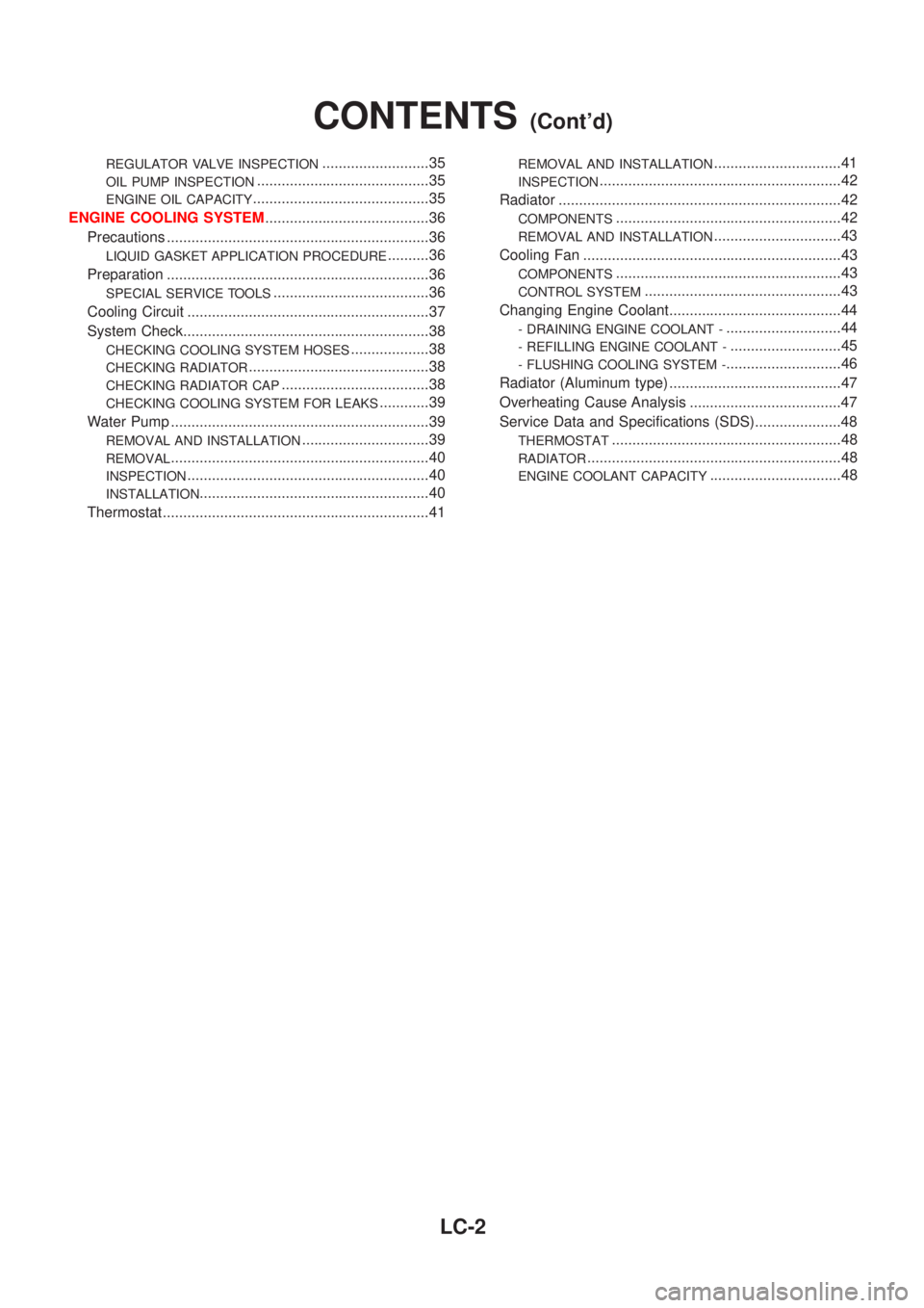
REGULATOR VALVE INSPECTION..........................35
OIL PUMP INSPECTION..........................................35
ENGINE OIL CAPACITY...........................................35
ENGINE COOLING SYSTEM........................................36
Precautions ................................................................36
LIQUID GASKET APPLICATION PROCEDURE..........36
Preparation ................................................................36
SPECIAL SERVICE TOOLS......................................36
Cooling Circuit ...........................................................37
System Check............................................................38
CHECKING COOLING SYSTEM HOSES...................38
CHECKING RADIATOR............................................38
CHECKING RADIATOR CAP....................................38
CHECKING COOLING SYSTEM FOR LEAKS............39
Water Pump ...............................................................39
REMOVAL AND INSTALLATION...............................39
REMOVAL...............................................................40
INSPECTION...........................................................40
INSTALLATION........................................................40
Thermostat .................................................................41
REMOVAL AND INSTALLATION...............................41
INSPECTION...........................................................42
Radiator .....................................................................42
COMPONENTS.......................................................42
REMOVAL AND INSTALLATION...............................43
Cooling Fan ...............................................................43
COMPONENTS.......................................................43
CONTROL SYSTEM................................................43
Changing Engine Coolant..........................................44
- DRAINING ENGINE COOLANT -............................44
- REFILLING ENGINE COOLANT -...........................45
- FLUSHING COOLING SYSTEM -............................46
Radiator (Aluminum type) ..........................................47
Overheating Cause Analysis .....................................47
Service Data and Specifications (SDS).....................48
THERMOSTAT........................................................48
RADIATOR..............................................................48
ENGINE COOLANT CAPACITY................................48
CONTENTS(Cont'd)
LC-2
Page 2509 of 2898
SEM164F
AEM080
Precautions
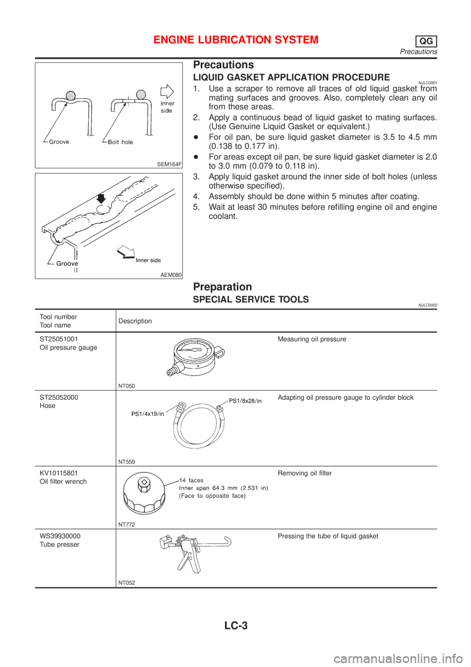
LIQUID GASKET APPLICATION PROCEDURENJLC00011. Use a scraper to remove all traces of old liquid gasket from
mating surfaces and grooves. Also, completely clean any oil
from these areas.
2. Apply a continuous bead of liquid gasket to mating surfaces.
(Use Genuine Liquid Gasket or equivalent.)
+For oil pan, be sure liquid gasket diameter is 3.5 to 4.5 mm
(0.138 to 0.177 in).
+For areas except oil pan, be sure liquid gasket diameter is 2.0
to 3.0 mm (0.079 to 0.118 in).
3. Apply liquid gasket around the inner side of bolt holes (unless
otherwise specified).
4. Assembly should be done within 5 minutes after coating.
5. Wait at least 30 minutes before refilling engine oil and engine
coolant.
Preparation
SPECIAL SERVICE TOOLSNJLC0002
Tool number
Tool nameDescription
ST25051001
Oil pressure gauge
NT050
Measuring oil pressure
ST25052000
Hose
NT559
Adapting oil pressure gauge to cylinder block
KV10115801
Oil filter wrench
NT772
Removing oil filter
WS39930000
Tube presser
NT052
Pressing the tube of liquid gasket
ENGINE LUBRICATION SYSTEMQG
Precautions
LC-3
Page 2517 of 2898
SEM164F
AEM080
Precautions
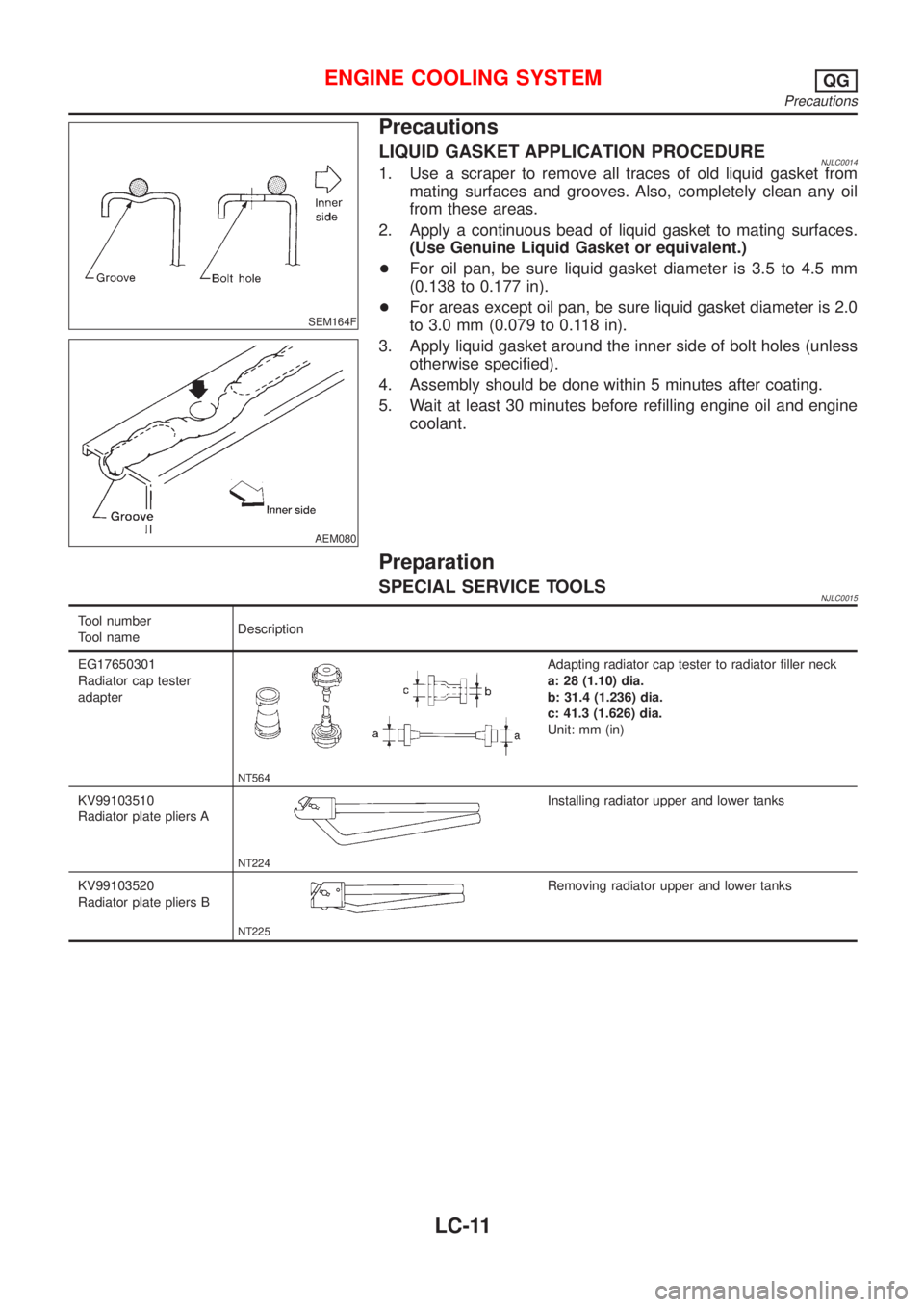
LIQUID GASKET APPLICATION PROCEDURENJLC00141. Use a scraper to remove all traces of old liquid gasket from
mating surfaces and grooves. Also, completely clean any oil
from these areas.
2. Apply a continuous bead of liquid gasket to mating surfaces.
(Use Genuine Liquid Gasket or equivalent.)
+For oil pan, be sure liquid gasket diameter is 3.5 to 4.5 mm
(0.138 to 0.177 in).
+For areas except oil pan, be sure liquid gasket diameter is 2.0
to 3.0 mm (0.079 to 0.118 in).
3. Apply liquid gasket around the inner side of bolt holes (unless
otherwise specified).
4. Assembly should be done within 5 minutes after coating.
5. Wait at least 30 minutes before refilling engine oil and engine
coolant.
Preparation
SPECIAL SERVICE TOOLSNJLC0015
Tool number
Tool nameDescription
EG17650301
Radiator cap tester
adapter
NT564
Adapting radiator cap tester to radiator filler neck
a: 28 (1.10) dia.
b: 31.4 (1.236) dia.
c: 41.3 (1.626) dia.
Unit: mm (in)
KV99103510
Radiator plate pliers A
NT224
Installing radiator upper and lower tanks
KV99103520
Radiator plate pliers B
NT225
Removing radiator upper and lower tanks
ENGINE COOLING SYSTEMQG
Precautions
LC-11