2001 NISSAN ALMERA engine oil
[x] Cancel search: engine oilPage 1838 of 2898
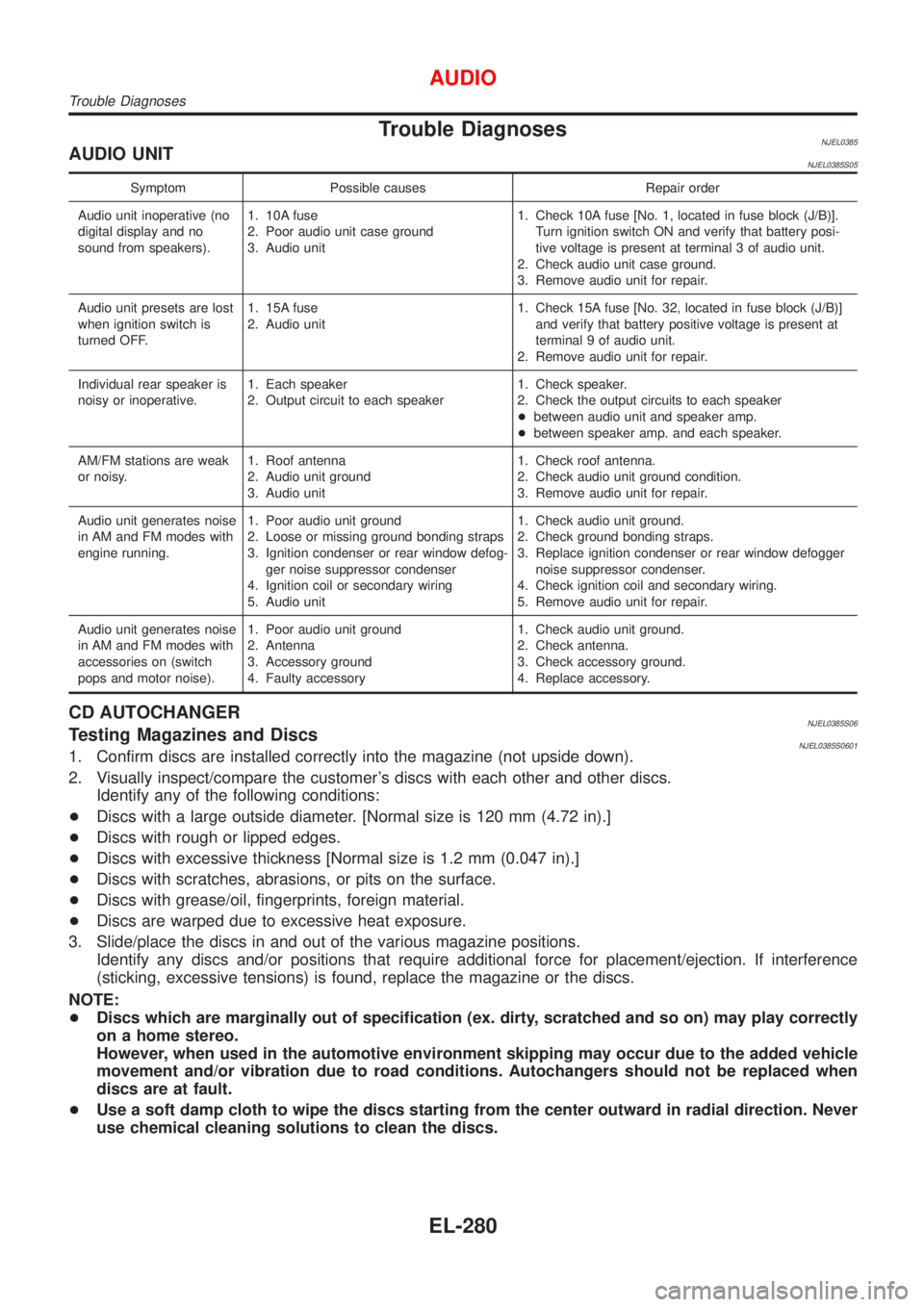
Trouble DiagnosesNJEL0385AUDIO UNITNJEL0385S05
Symptom Possible causes Repair order
Audio unit inoperative (no
digital display and no
sound from speakers).1. 10A fuse
2. Poor audio unit case ground
3. Audio unit1. Check 10A fuse [No. 1, located in fuse block (J/B)].
Turn ignition switch ON and verify that battery posi-
tive voltage is present at terminal 3 of audio unit.
2. Check audio unit case ground.
3. Remove audio unit for repair.
Audio unit presets are lost
when ignition switch is
turned OFF.1. 15A fuse
2. Audio unit1. Check 15A fuse [No. 32, located in fuse block (J/B)]
and verify that battery positive voltage is present at
terminal 9 of audio unit.
2. Remove audio unit for repair.
Individual rear speaker is
noisy or inoperative.1. Each speaker
2. Output circuit to each speaker1. Check speaker.
2. Check the output circuits to each speaker
+between audio unit and speaker amp.
+between speaker amp. and each speaker.
AM/FM stations are weak
or noisy.1. Roof antenna
2. Audio unit ground
3. Audio unit1. Check roof antenna.
2. Check audio unit ground condition.
3. Remove audio unit for repair.
Audio unit generates noise
in AM and FM modes with
engine running.1. Poor audio unit ground
2. Loose or missing ground bonding straps
3. Ignition condenser or rear window defog-
ger noise suppressor condenser
4. Ignition coil or secondary wiring
5. Audio unit1. Check audio unit ground.
2. Check ground bonding straps.
3. Replace ignition condenser or rear window defogger
noise suppressor condenser.
4. Check ignition coil and secondary wiring.
5. Remove audio unit for repair.
Audio unit generates noise
in AM and FM modes with
accessories on (switch
pops and motor noise).1. Poor audio unit ground
2. Antenna
3. Accessory ground
4. Faulty accessory1. Check audio unit ground.
2. Check antenna.
3. Check accessory ground.
4. Replace accessory.
CD AUTOCHANGERNJEL0385S06Testing Magazines and DiscsNJEL0385S06011. Confirm discs are installed correctly into the magazine (not upside down).
2. Visually inspect/compare the customer's discs with each other and other discs.
Identify any of the following conditions:
+Discs with a large outside diameter. [Normal size is 120 mm (4.72 in).]
+Discs with rough or lipped edges.
+Discs with excessive thickness [Normal size is 1.2 mm (0.047 in).]
+Discs with scratches, abrasions, or pits on the surface.
+Discs with grease/oil, fingerprints, foreign material.
+Discs are warped due to excessive heat exposure.
3. Slide/place the discs in and out of the various magazine positions.
Identify any discs and/or positions that require additional force for placement/ejection. If interference
(sticking, excessive tensions) is found, replace the magazine or the discs.
NOTE:
+Discs which are marginally out of specification (ex. dirty, scratched and so on) may play correctly
on a home stereo.
However, when used in the automotive environment skipping may occur due to the added vehicle
movement and/or vibration due to road conditions. Autochangers should not be replaced when
discs are at fault.
+Use a soft damp cloth to wipe the discs starting from the center outward in radial direction. Never
use chemical cleaning solutions to clean the discs.
AUDIO
Trouble Diagnoses
EL-280
Page 2135 of 2898
ENGINE MECHANICAL
SECTION
EM
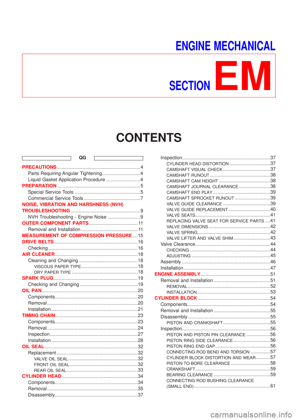
CONTENTS
QG
PRECAUTIONS...............................................................4
Parts Requiring Angular Tightening .............................4
Liquid Gasket Application Procedure ..........................4
PREPARATION...............................................................5
Special Service Tools ..................................................5
Commercial Service Tools ...........................................7
NOISE, VIBRATION AND HARSHNESS (NVH)
TROUBLESHOOTING.....................................................9
NVH Troubleshooting - Engine Noise .........................9
OUTER COMPONENT PARTS..................................... 11
Removal and Installation ........................................... 11
MEASUREMENT OF COMPRESSION PRESSURE....15
DRIVE BELTS................................................................16
Checking ....................................................................16
AIR CLEANER...............................................................18
Cleaning and Changing .............................................18
VISCOUS PAPER TYPE...........................................18
DRY PAPER TYPE..................................................18
SPARK PLUG................................................................19
Checking and Changing ............................................19
OIL PAN.........................................................................20
Components...............................................................20
Removal .....................................................................20
Installation ..................................................................21
TIMING CHAIN..............................................................23
Components...............................................................23
Removal .....................................................................24
Inspection...................................................................27
Installation ..................................................................28
OIL SEAL.......................................................................32
Replacement ..............................................................32
VALVE OIL SEAL.....................................................32
FRONT OIL SEAL....................................................32
REAR OIL SEAL......................................................33
CYLINDER HEAD..........................................................34
Components...............................................................34
Removal .....................................................................35
Disassembly...............................................................37Inspection...................................................................37
CYLINDER HEAD DISTORTION...............................37
CAMSHAFT VISUAL CHECK....................................37
CAMSHAFT RUNOUT..............................................38
CAMSHAFT CAM HEIGHT.......................................38
CAMSHAFT JOURNAL CLEARANCE........................38
CAMSHAFT END PLAY............................................39
CAMSHAFT SPROCKET RUNOUT...........................39
VALVE GUIDE CLEARANCE....................................39
VALVE GUIDE REPLACEMENT................................40
VALVE SEATS.........................................................41
REPLACING VALVE SEAT FOR SERVICE PARTS....41
VALVE DIMENSIONS...............................................42
VALVE SPRING.......................................................42
VALVE LIFTER AND VALVE SHIM............................43
Valve Clearance.........................................................44
CHECKING.............................................................44
ADJUSTING............................................................45
Assembly ...................................................................46
Installation ..................................................................47
ENGINE ASSEMBLY.....................................................51
Removal and Installation ...........................................51
REMOVAL...............................................................52
INSTALLATION........................................................53
CYLINDER BLOCK.......................................................54
Components...............................................................54
Removal and Installation ...........................................55
Disassembly...............................................................55
PISTON AND CRANKSHAFT....................................55
Inspection...................................................................56
PISTON AND PISTON PIN CLEARANCE..................56
PISTON RING SIDE CLEARANCE............................56
PISTON RING END GAP..........................................56
CONNECTING ROD BEND AND TORSION...............57
CYLINDER BLOCK DISTORTION AND WEAR...........57
PISTON-TO-BORE CLEARANCE..............................58
CRANKSHAFT.........................................................59
BEARING CLEARANCE...........................................59
CONNECTING ROD BUSHING CLEARANCE
(SMALL END)
..........................................................61
Page 2136 of 2898
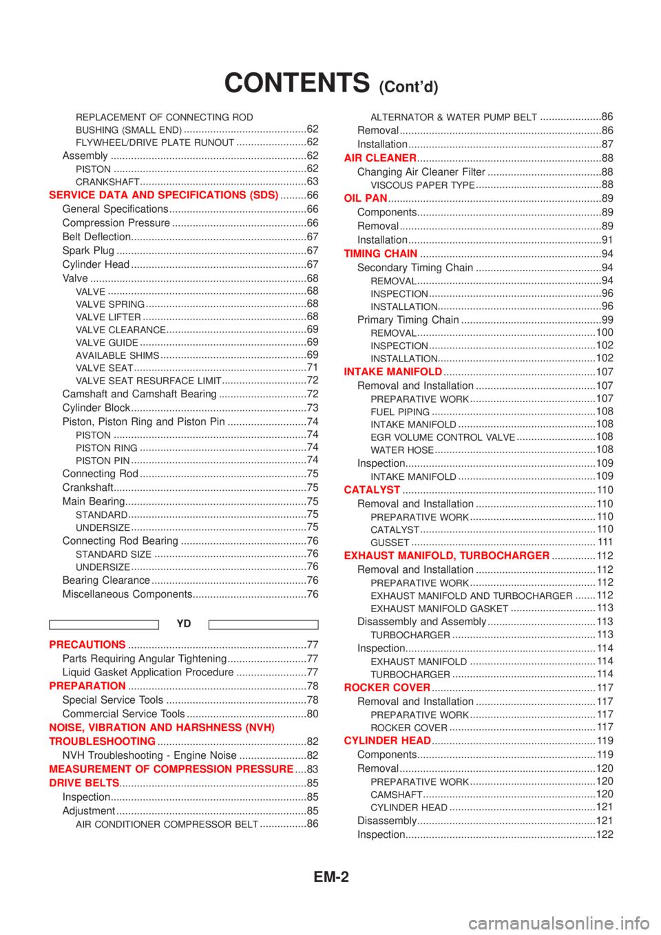
REPLACEMENT OF CONNECTING ROD
BUSHING (SMALL END)
..........................................62
FLYWHEEL/DRIVE PLATE RUNOUT........................62
Assembly ...................................................................62
PISTON..................................................................62
CRANKSHAFT.........................................................63
SERVICE DATA AND SPECIFICATIONS (SDS).........66
General Specifications ...............................................66
Compression Pressure ..............................................66
Belt Deflection............................................................67
Spark Plug .................................................................67
Cylinder Head ............................................................67
Valve ..........................................................................68
VALVE....................................................................68
VALVE SPRING.......................................................68
VALVE LIFTER........................................................68
VALVE CLEARANCE................................................69
VALVE GUIDE.........................................................69
AVAILABLE SHIMS..................................................69
VALVE SEAT...........................................................71
VALVE SEAT RESURFACE LIMIT.............................72
Camshaft and Camshaft Bearing ..............................72
Cylinder Block ............................................................73
Piston, Piston Ring and Piston Pin ...........................74
PISTON..................................................................74
PISTON RING.........................................................74
PISTON PIN............................................................74
Connecting Rod .........................................................75
Crankshaft..................................................................75
Main Bearing..............................................................75
STANDARD.............................................................75
UNDERSIZE............................................................75
Connecting Rod Bearing ...........................................76
STANDARD SIZE....................................................76
UNDERSIZE............................................................76
Bearing Clearance .....................................................76
Miscellaneous Components.......................................76
YD
PRECAUTIONS.............................................................77
Parts Requiring Angular Tightening ...........................77
Liquid Gasket Application Procedure ........................77
PREPARATION.............................................................78
Special Service Tools ................................................78
Commercial Service Tools .........................................80
NOISE, VIBRATION AND HARSHNESS (NVH)
TROUBLESHOOTING...................................................82
NVH Troubleshooting - Engine Noise .......................82
MEASUREMENT OF COMPRESSION PRESSURE....83
DRIVE BELTS................................................................85
Inspection...................................................................85
Adjustment .................................................................85
AIR CONDITIONER COMPRESSOR BELT................86
ALTERNATOR & WATER PUMP BELT.....................86
Removal .....................................................................86
Installation ..................................................................87
AIR CLEANER...............................................................88
Changing Air Cleaner Filter .......................................88
VISCOUS PAPER TYPE...........................................88
OIL PAN.........................................................................89
Components...............................................................89
Removal .....................................................................89
Installation ..................................................................91
TIMING CHAIN..............................................................94
Secondary Timing Chain ...........................................94
REMOVAL...............................................................94
INSPECTION...........................................................96
INSTALLATION........................................................96
Primary Timing Chain ................................................99
REMOVAL.............................................................100
INSPECTION.........................................................102
INSTALLATION......................................................102
INTAKE MANIFOLD....................................................107
Removal and Installation .........................................107
PREPARATIVE WORK...........................................107
FUEL PIPING........................................................108
INTAKE MANIFOLD...............................................108
EGR VOLUME CONTROL VALVE...........................108
WATER HOSE.......................................................108
Inspection.................................................................109
INTAKE MANIFOLD...............................................109
CATALYST.................................................................. 110
Removal and Installation ......................................... 110
PREPARATIVE WORK........................................... 110
CATALYST............................................................ 110
GUSSET............................................................... 111
EXHAUST MANIFOLD, TURBOCHARGER............... 112
Removal and Installation ......................................... 112
PREPARATIVE WORK........................................... 112
EXHAUST MANIFOLD AND TURBOCHARGER....... 112
EXHAUST MANIFOLD GASKET............................. 113
Disassembly and Assembly ..................................... 113
TURBOCHARGER................................................. 113
Inspection................................................................. 114
EXHAUST MANIFOLD........................................... 114
TURBOCHARGER................................................. 114
ROCKER COVER........................................................ 117
Removal and Installation ......................................... 117
PREPARATIVE WORK........................................... 117
ROCKER COVER.................................................. 117
CYLINDER HEAD........................................................ 119
Components............................................................. 119
Removal ...................................................................120
PREPARATIVE WORK...........................................120
CAMSHAFT...........................................................120
CYLINDER HEAD..................................................121
Disassembly.............................................................121
Inspection.................................................................122
CONTENTS(Cont'd)
EM-2
Page 2137 of 2898
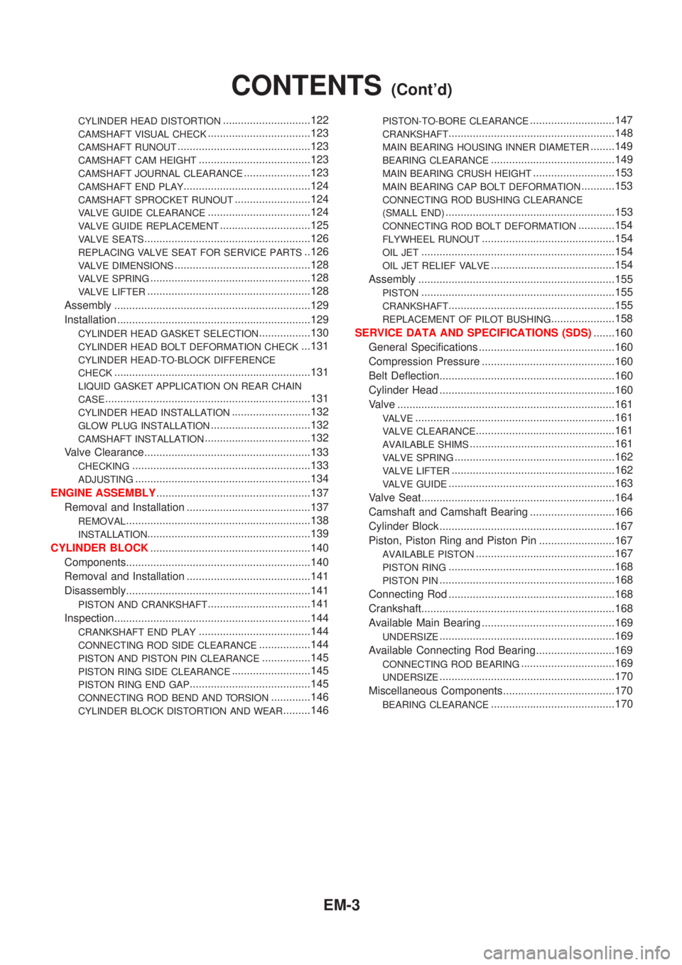
CYLINDER HEAD DISTORTION.............................122
CAMSHAFT VISUAL CHECK..................................123
CAMSHAFT RUNOUT............................................123
CAMSHAFT CAM HEIGHT.....................................123
CAMSHAFT JOURNAL CLEARANCE......................123
CAMSHAFT END PLAY..........................................124
CAMSHAFT SPROCKET RUNOUT.........................124
VALVE GUIDE CLEARANCE..................................124
VALVE GUIDE REPLACEMENT..............................125
VALVE SEATS.......................................................126
REPLACING VALVE SEAT FOR SERVICE PARTS..126
VALVE DIMENSIONS.............................................128
VALVE SPRING.....................................................128
VALVE LIFTER......................................................128
Assembly .................................................................129
Installation ................................................................129
CYLINDER HEAD GASKET SELECTION.................130
CYLINDER HEAD BOLT DEFORMATION CHECK...131
CYLINDER HEAD-TO-BLOCK DIFFERENCE
CHECK
.................................................................131
LIQUID GASKET APPLICATION ON REAR CHAIN
CASE
....................................................................131
CYLINDER HEAD INSTALLATION..........................132
GLOW PLUG INSTALLATION.................................132
CAMSHAFT INSTALLATION...................................132
Valve Clearance.......................................................133
CHECKING...........................................................133
ADJUSTING..........................................................134
ENGINE ASSEMBLY...................................................137
Removal and Installation .........................................137
REMOVAL.............................................................138
INSTALLATION......................................................139
CYLINDER BLOCK.....................................................140
Components.............................................................140
Removal and Installation .........................................141
Disassembly.............................................................141
PISTON AND CRANKSHAFT..................................141
Inspection.................................................................144
CRANKSHAFT END PLAY.....................................144
CONNECTING ROD SIDE CLEARANCE.................144
PISTON AND PISTON PIN CLEARANCE................145
PISTON RING SIDE CLEARANCE..........................145
PISTON RING END GAP........................................145
CONNECTING ROD BEND AND TORSION.............146
CYLINDER BLOCK DISTORTION AND WEAR.........146
PISTON-TO-BORE CLEARANCE............................147
CRANKSHAFT.......................................................148
MAIN BEARING HOUSING INNER DIAMETER........149
BEARING CLEARANCE.........................................149
MAIN BEARING CRUSH HEIGHT...........................153
MAIN BEARING CAP BOLT DEFORMATION...........153
CONNECTING ROD BUSHING CLEARANCE
(SMALL END)
........................................................153
CONNECTING ROD BOLT DEFORMATION............154
FLYWHEEL RUNOUT............................................154
OIL JET................................................................154
OIL JET RELIEF VALVE.........................................154
Assembly .................................................................155
PISTON................................................................155
CRANKSHAFT.......................................................155
REPLACEMENT OF PILOT BUSHING.....................158
SERVICE DATA AND SPECIFICATIONS (SDS).......160
General Specifications .............................................160
Compression Pressure ............................................160
Belt Deflection..........................................................160
Cylinder Head ..........................................................160
Valve ........................................................................161
VALVE..................................................................161
VALVE CLEARANCE..............................................161
AVAILABLE SHIMS................................................161
VALVE SPRING.....................................................162
VALVE LIFTER......................................................162
VALVE GUIDE.......................................................163
Valve Seat................................................................164
Camshaft and Camshaft Bearing ............................166
Cylinder Block ..........................................................167
Piston, Piston Ring and Piston Pin .........................167
AVAILABLE PISTON..............................................167
PISTON RING.......................................................168
PISTON PIN..........................................................168
Connecting Rod .......................................................168
Crankshaft................................................................168
Available Main Bearing ............................................169
UNDERSIZE..........................................................169
Available Connecting Rod Bearing..........................169
CONNECTING ROD BEARING...............................169
UNDERSIZE..........................................................170
Miscellaneous Components.....................................170
BEARING CLEARANCE.........................................170
CONTENTS(Cont'd)
EM-3
Page 2138 of 2898
Parts Requiring Angular TighteningNJEM0001+Use an angle wrench for the final tightening of the following
engine parts:
a) Cylinder head bolts
b) Main bearing cap bolts
c) Connecting rod cap nuts
+Do not use a torque value for final tightening.
+The torque value for these parts are for a preliminary step.
+Ensure thread and seat surfaces are clean and coated with
engine oil.
SEM164F
AEM080
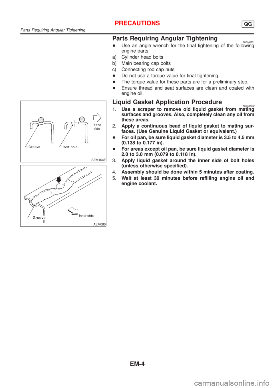
Liquid Gasket Application ProcedureNJEM00021.Use a scraper to remove old liquid gasket from mating
surfaces and grooves. Also, completely clean any oil from
these areas.
2.Apply a continuous bead of liquid gasket to mating sur-
faces. (Use Genuine Liquid Gasket or equivalent.)
+For oil pan, be sure liquid gasket diameter is 3.5 to 4.5 mm
(0.138 to 0.177 in).
+For areas except oil pan, be sure liquid gasket diameter is
2.0 to 3.0 mm (0.079 to 0.118 in).
3.Apply liquid gasket around the inner side of bolt holes
(unless otherwise specified).
4.Assembly should be done within 5 minutes after coating.
5.Wait at least 30 minutes before refilling engine oil and
engine coolant.
PRECAUTIONSQG
Parts Requiring Angular Tightening
EM-4
Page 2139 of 2898
Special Service ToolsNJEM0003
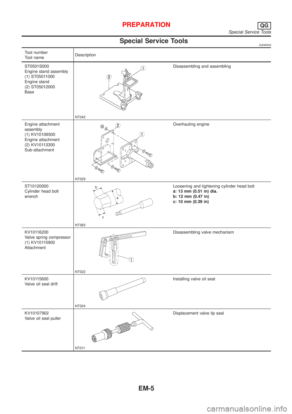
Tool number
Tool nameDescription
ST0501S000
Engine stand assembly
(1) ST05011000
Engine stand
(2) ST05012000
Base
NT042
Disassembling and assembling
Engine attachment
assembly
(1) KV10106500
Engine attachment
(2) KV10113300
Sub-attachment
NT029
Overhauling engine
ST10120000
Cylinder head bolt
wrench
NT583
Loosening and tightening cylinder head bolt
a: 13 mm (0.51 in) dia.
b: 12 mm (0.47 in)
c: 10 mm (0.39 in)
KV10116200
Valve spring compressor
(1) KV10115900
Attachment
NT022
Disassembling valve mechanism
KV10115600
Valve oil seal drift
NT024
Installing valve oil seal
KV10107902
Valve oil seal puller
NT011
Displacement valve lip seal
PREPARATIONQG
Special Service Tools
EM-5
Page 2143 of 2898
NJEM0005
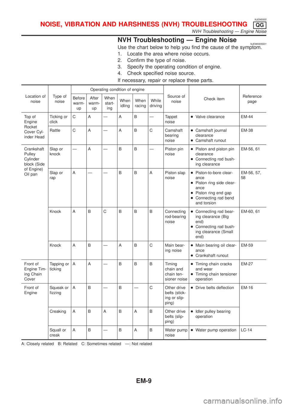
NVH Troubleshooting Ð Engine NoiseNJEM0005S01Use the chart below to help you find the cause of the symptom.
1. Locate the area where noise occurs.
2. Confirm the type of noise.
3. Specify the operating condition of engine.
4. Check specified noise source.
If necessary, repair or replace these parts.
Location of
noiseType of
noiseOperating condition of engine
Source of
noiseCheck itemReference
page Before
warm-
upAfter
warm-
upWhen
start-
ingWhen
idlingWhen
racingWhile
driving
To p o f
Engine
Rocket
Cover Cyl-
inder HeadTicking or
clickC A Ð A B Ð Tappet
noise+Valve clearance EM-44
Rattle C A Ð A B C Camshaft
bearing
noise+Camshaft journal
clearance
+Camshaft runoutEM-38
Crankshaft
Pulley
Cylinder
block (Side
of Engine)
Oil panSlap or
knockÐ A Ð B B Ð Piston pin
noise+Piston and piston pin
clearance
+Connecting rod bush-
ing clearanceEM-56, 61
Slap or
rapA Ð Ð B B A Piston slap
noise+Piston-to-bore clear-
ance
+Piston ring side clear-
ance
+Piston ring end gap
+Connecting rod bend
and torsionEM-56, 57,
58
Knock A B CB B B Connecting
rod-bearing
noise+Connecting rod bear-
ing clearance (Big
end)
+Connecting rod bush-
ing clearance (Small
end)EM-60, 61
Knock A B Ð A B C Main bear-
ing noise+Main bearing oil clear-
ance
+Crankshaft runoutEM-59
Front of
Engine Tim-
ing Chain
CoverTapping or
tickingAAÐBBBTiming
chain and
chain ten-
sioner noise+Timing chain cracks
and wear
+Timing chain tensioner
operationEM-27
Front of
EngineSqueak or
fizzingA B Ð B Ð C Other drive
belts (stick-
ing or slip-
ping)+Drive belts deflection EM-16
CreakingABABABOther drive
belts (slip-
ping)+Idler pulley bearing
operation
Squall or
creakABÐBABWater pump
noise+Water pump operation LC-14
A: Closely related B: Related C: Sometimes related Ð: Not related
NOISE, VIBRATION AND HARSHNESS (NVH) TROUBLESHOOTINGQG
NVH Troubleshooting Ð Engine Noise
EM-9
Page 2148 of 2898
YEM011
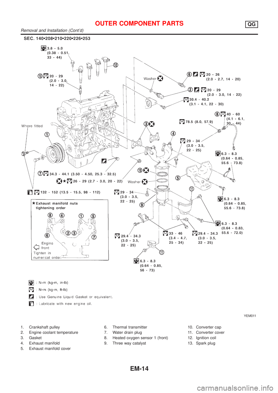
1. Crankshaft pulley
2. Engine coolant temperature
3. Gasket
4. Exhaust manifold
5. Exhaust manifold cover6. Thermal transmitter
7. Water drain plug
8. Heated oxygen sensor 1 (front)
9. Three way catalyst10. Converter cap
11. Converter cover
12. Ignition coil
13. Spark plug
OUTER COMPONENT PARTSQG
Removal and Installation (Cont'd)
EM-14