2001 NISSAN ALMERA N16 pump
[x] Cancel search: pumpPage 8 of 2493
Do not attempt to top off the fuel tank after the fuel pump nozzle
shuts off automatically. Continued refueling may cause fuel
overflow, resulting in fuel spray and possibly a fire.
WARNING:
To prevent ECM from storing the diagnostic trouble codes, do
not carelessly disconnect the harness connectors which are
related to the engine control system and TCM (Transmission
Control Module) system. The connectors should be discon-
nected only when working according to the WORK FLOW of
TROUBLE DIAGNOSES in EC and AT sections.
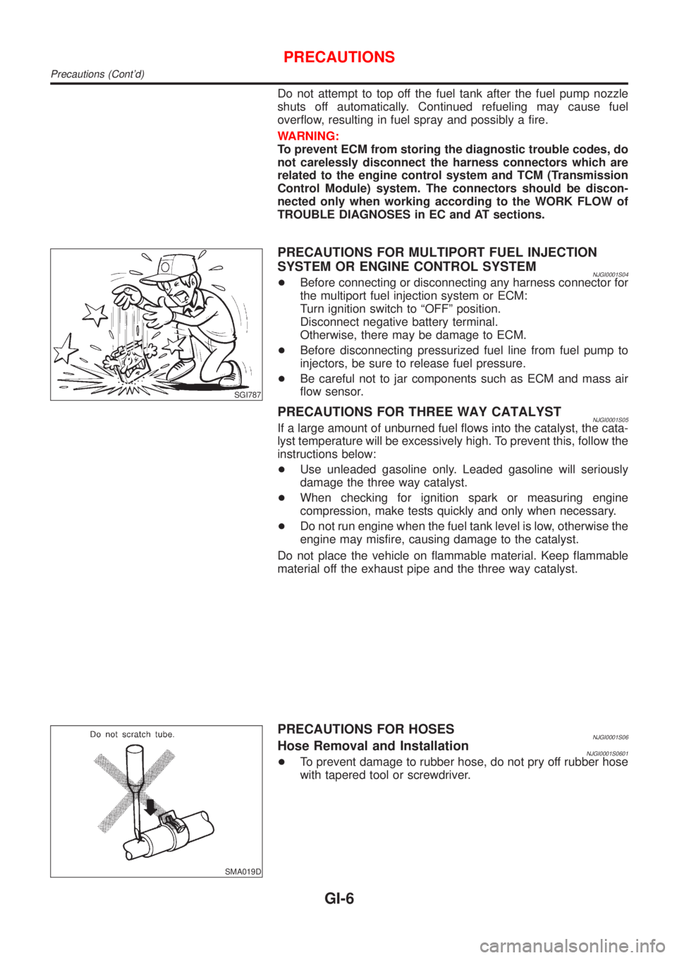
SGI787
PRECAUTIONS FOR MULTIPORT FUEL INJECTION
SYSTEM OR ENGINE CONTROL SYSTEM
NJGI0001S04+Before connecting or disconnecting any harness connector for
the multiport fuel injection system or ECM:
Turn ignition switch to ªOFFº position.
Disconnect negative battery terminal.
Otherwise, there may be damage to ECM.
+Before disconnecting pressurized fuel line from fuel pump to
injectors, be sure to release fuel pressure.
+Be careful not to jar components such as ECM and mass air
flow sensor.
PRECAUTIONS FOR THREE WAY CATALYSTNJGI0001S05If a large amount of unburned fuel flows into the catalyst, the cata-
lyst temperature will be excessively high. To prevent this, follow the
instructions below:
+Use unleaded gasoline only. Leaded gasoline will seriously
damage the three way catalyst.
+When checking for ignition spark or measuring engine
compression, make tests quickly and only when necessary.
+Do not run engine when the fuel tank level is low, otherwise the
engine may misfire, causing damage to the catalyst.
Do not place the vehicle on flammable material. Keep flammable
material off the exhaust pipe and the three way catalyst.
SMA019D
PRECAUTIONS FOR HOSESNJGI0001S06Hose Removal and InstallationNJGI0001S0601+To prevent damage to rubber hose, do not pry off rubber hose
with tapered tool or screwdriver.
PRECAUTIONS
Precautions (Cont'd)
GI-6
Page 54 of 2493

NEW TERMNEW ACRONYM /
ABBREVIATIONOLD TERM
Malfunction indicator lamp MIL Check engine light
Manifold absolute pressure MAP ***
Manifold absolute pressure sensor MAPS ***
Manifold differential pressure MDP ***
Manifold differential pressure sensor MDPS ***
Manifold surface temperature MST ***
Manifold surface temperature sensor MSTS ***
Manifold vacuum zone MVZ ***
Manifold vacuum zone sensor MVZS ***
Mass air flow sensor MAFS Air flow meter
Mixture control solenoid valve MC solenoid valve Air-fuel ratio control solenoid valve
Multiport fuel injection system MFI system Fuel injection control
Nonvolatile random access memory NVRAM ***
On board diagnostic system OBD system Self-diagnoses
Open loop OL Open loop
Oxidation catalyst OC Catalyst
Oxidation catalytic converter system OC system ***
Oxygen sensor O2S Exhaust gas sensor
Park position switch *** Park switch
Park/neutral position switch PNP switch Park/neutral switch
Inhibitor switch
Neutral position switch
Periodic trap oxidizer system PTOX system ***
Positive crankcase ventilation PCV Positive crankcase ventilation
Positive crankcase ventilation valve PCV valve PCV valve
Powertrain control module PCM ***
Programmable read only memory PROM ***
Pulsed secondary air injection control
solenoid valvePAIRC solenoid valve AIV control solenoid valve
Pulsed secondary air injection system PAIR system Air induction valve (AIV) control
Pulsed secondary air injection valve PAIR valve Air induction valve
Random access memory RAM ***
Read only memory ROM ***
Scan tool ST ***
Secondary air injection pump AIR pump ***
Secondary air injection system AIR system ***
Sequential multiport fuel injection system SFI system Sequential fuel injection
Service reminder indicator SRI ***
ISO 15031-2 TERMINOLOGY LIST
ISO 15031-2 (Cont'd)
GI-52
Page 80 of 2493

REPLACEMENT OF CONNECTING ROD
BUSHING (SMALL END)
..........................................60
FLYWHEEL/DRIVE PLATE RUNOUT........................60
Assembly ...................................................................60
PISTON..................................................................60
CRANKSHAFT.........................................................61
SERVICE DATA AND SPECIFICATIONS (SDS).........64
General Specifications ...............................................64
Compression Pressure ..............................................64
Belt Deflection............................................................64
Spark Plug .................................................................65
Cylinder Head ............................................................65
Valve ..........................................................................66
VALVE....................................................................66
VALVE SPRING.......................................................66
VALVE LIFTER........................................................66
VALVE CLEARANCE................................................67
VALVE GUIDE.........................................................67
AVAILABLE SHIMS..................................................67
VALVE SEAT...........................................................70
VALVE SEAT RESURFACE LIMIT.............................71
Camshaft and Camshaft Bearing ..............................71
Cylinder Block ............................................................72
Piston, Piston Ring and Piston Pin ...........................73
PISTON..................................................................73
PISTON RING.........................................................73
PISTON PIN............................................................73
Connecting Rod .........................................................74
Crankshaft..................................................................74
Main Bearing..............................................................74
STANDARD.............................................................74
UNDERSIZE............................................................74
Connecting Rod Bearing ...........................................75
STANDARD SIZE....................................................75
UNDERSIZE............................................................75
Bearing Clearance .....................................................75
Miscellaneous Components.......................................75
YD
PRECAUTIONS.............................................................76
Parts Requiring Angular Tightening ...........................76
Liquid Gasket Application Procedure ........................76
PREPARATION.............................................................77
Special Service Tools ................................................77
Commercial Service Tools .........................................79
NOISE, VIBRATION AND HARSHNESS (NVH)
TROUBLESHOOTING...................................................81
NVH Troubleshooting - Engine Noise .......................81
MEASUREMENT OF COMPRESSION PRESSURE....82
DRIVE BELTS................................................................84
Inspection...................................................................84
Adjustment .................................................................84
AIR CONDITIONER COMPRESSOR BELT................85
ALTERNATOR & WATER PUMP BELT.....................85
Removal .....................................................................85
Installation ..................................................................86
AIR CLEANER...............................................................87
Changing Air Cleaner Filter .......................................87
VISCOUS PAPER TYPE...........................................87
OIL PAN.........................................................................88
Components...............................................................88
Removal .....................................................................88
Installation ..................................................................90
TIMING CHAIN..............................................................93
Secondary Timing Chain ...........................................93
REMOVAL...............................................................93
INSPECTION...........................................................95
INSTALLATION........................................................95
Primary Timing Chain ................................................98
REMOVAL...............................................................99
INSPECTION.........................................................101
INSTALLATION......................................................101
INTAKE MANIFOLD....................................................106
Removal and Installation .........................................106
PREPARATIVE WORK...........................................106
FUEL PIPING........................................................107
INTAKE MANIFOLD...............................................107
EGR VOLUME CONTROL VALVE...........................107
WATER HOSE.......................................................107
Inspection.................................................................108
INTAKE MANIFOLD...............................................108
CATALYST..................................................................109
Removal and Installation .........................................109
PREPARATIVE WORK...........................................109
CATALYST............................................................109
GUSSET............................................................... 110
EXHAUST MANIFOLD, TURBOCHARGER............... 111
Removal and Installation ......................................... 111
PREPARATIVE WORK........................................... 111
EXHAUST MANIFOLD AND TURBOCHARGER....... 111
EXHAUST MANIFOLD GASKET............................. 112
Disassembly and Assembly ..................................... 112
TURBOCHARGER................................................. 112
Inspection................................................................. 113
EXHAUST MANIFOLD........................................... 113
TURBOCHARGER................................................. 113
ROCKER COVER........................................................ 116
Removal and Installation ......................................... 116
PREPARATIVE WORK........................................... 116
ROCKER COVER.................................................. 116
CYLINDER HEAD........................................................ 118
Components............................................................. 118
Removal ................................................................... 119
PREPARATIVE WORK........................................... 119
CAMSHAFT........................................................... 119
CYLINDER HEAD..................................................120
Disassembly.............................................................120
Inspection.................................................................121
CONTENTS(Cont'd)
EM-2
Page 87 of 2493

NJEM0005
NVH Troubleshooting Ð Engine NoiseNJEM0005S01Use the chart below to help you find the cause of the symptom.
1. Locate the area where noise occurs.
2. Confirm the type of noise.
3. Specify the operating condition of engine.
4. Check specified noise source.
If necessary, repair or replace these parts.
Location of
noiseType of
noiseOperating condition of engine
Source of
noiseCheck itemReference
page Before
warm-
upAfter
warm-
upWhen
start-
ingWhen
idlingWhen
racingWhile
driving
To p o f
Engine
Rocket
Cover Cyl-
inder HeadTicking or
clickC A Ð A B Ð Tappet
noise+Valve clearance EM-42
Rattle C A Ð A B C Camshaft
bearing
noise+Camshaft journal
clearance
+Camshaft runoutEM-37
Crankshaft
Pulley
Cylinder
block (Side
of Engine)
Oil panSlap or
knockÐ A Ð B B Ð Piston pin
noise+Piston and piston pin
clearance
+Connecting rod bush-
ing clearanceEM-54, 59
Slap or
rapA Ð Ð B B A Piston slap
noise+Piston-to-bore clear-
ance
+Piston ring side clear-
ance
+Piston ring end gap
+Connecting rod bend
and torsionEM-54, 55,
56
Knock A B CB B B Connecting
rod-bearing
noise+Connecting rod bear-
ing clearance (Big
end)
+Connecting rod bush-
ing clearance (Small
end)EM-58, 59
Knock A B Ð A B C Main bear-
ing noise+Main bearing oil clear-
ance
+Crankshaft runoutEM-57
Front of
Engine Tim-
ing Chain
CoverTapping or
tickingAAÐBBBTiming
chain and
chain ten-
sioner noise+Timing chain cracks
and wear
+Timing chain tensioner
operationEM-26
Front of
EngineSqueak or
fizzingA B Ð B Ð C Other drive
belts (stick-
ing or slip-
ping)+Drive belts deflection EM-15
CreakingABABABOther drive
belts (slip-
ping)+Idler pulley bearing
operation
Squall or
creakABÐBABWater pump
noise+Water pump operation LC-14
A: Closely related B: Related C: Sometimes related Ð: Not related
NOISE, VIBRATION AND HARSHNESS (NVH) TROUBLESHOOTINGQG
NVH Troubleshooting Ð Engine Noise
EM-9
Page 89 of 2493
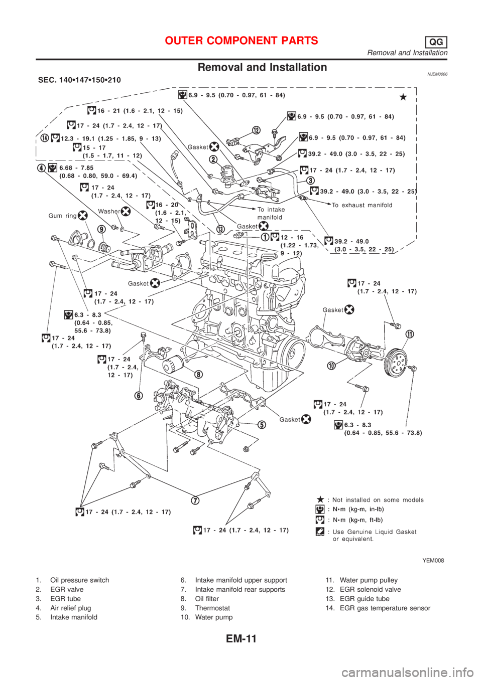
Removal and InstallationNJEM0006
YEM008
1. Oil pressure switch
2. EGR valve
3. EGR tube
4. Air relief plug
5. Intake manifold6. Intake manifold upper support
7. Intake manifold rear supports
8. Oil filter
9. Thermostat
10. Water pump11. Water pump pulley
12. EGR solenoid valve
13. EGR guide tube
14. EGR gas temperature sensor
OUTER COMPONENT PARTSQG
Removal and Installation
EM-11
Page 92 of 2493

NJEM0007
1. Warm up engine.
2. Turn ignition switch OFF.
3. Release fuel pressure.
Refer to EC-38, ªReleasing Fuel Pressureº.
4. Remove ignition coils.
5. Remove spark plugs.
+Clean area around plug with compressed air before removing
the spark plug.
SEM973E
AEM308
6. Attach a compression tester to No. 1 cylinder.
7. Depress accelerator pedal fully to keep throttle valve wide
open.
8. Crank engine and record highest gauge indication.
9. Repeat the measurement on each cylinder as shown above.
+Always use a fully-charged battery to obtain specified
engine speed.
Compression pressure: kPa (bar, kg/cm
2, psi)/rpm
QG18DE
Standard
1,324 (13.24, 13.5, 192)/350
Minimum
1,128 (11.28, 11.5, 164)/350
Maximum allowable difference between cylinders
98 (0.98, 1.0, 14)/350
QG15DE
Standard
1,372 (13.720, 13.99, 198.9)/350
Minimum
1,176 (11.759, 11.99, 170.5)/350
Maximum allowable difference between cylinders
98 (0.98, 1.0, 14)/350
10. If cylinder compression in one or more cylinders is low, pour a
small amount of engine oil into the cylinder through the spark
plug hole and retest compression.
+If adding oil improves cylinder compression, piston rings
may be worn or damaged. If so, replace piston rings after
checking piston.
+If pressure stays low, a valve may be sticking or seating
improperly. Inspect and repair valve and valve seat. Refer
to SDS, EM-70. If valve or valve seat is damaged
excessively, replace them.
+If compression in any two adjacent cylinders is low and if add-
ing oil does not improve compression, there is leakage past the
gasket surface. If so, replace cylinder head gasket.
11. Reinstall spark plugs, ignition coils and fuel pump fuse.
12. Perform ªSelf-diagnosis Procedureº referring to EC-68, ªHow
to Erase DTCº if any DTC appears.
MEASUREMENT OF COMPRESSION PRESSUREQG
EM-14
Page 94 of 2493

Belt deflection:
Unit: mm (in)
Applied engineUsed belt deflection
Deflection
of new belt
LimitDeflection
after
adjustment
AlternatorWith air
conditioner
compressorQG15´18DE 8.1 (0.319)5.3 - 5.7
(0.209 -
0.224)4.5 - 5.0
(0.177 -
0.197)
Without air
conditioner
compressorQG15´18DE10.2
(0.402)6.5 - 7.0
(0.256 -
0.276)5.5 - 6.1
(0.217 -
0.240)
Power steering oil
pumpQG15DE 8.5 (0.335)5.2 - 5.8
(0.205 -
0.228)4.6 - 5.2
(0.181 -
0.205)
QG18DE 7.1 (0.280)4.4 - 4.9
(0.173 -
0.193)3.9 - 4.4
(0.154 -
0.173)
Applied pushing force 98 N (10 kg, 22 lb)
Inspect drive belt deflections when engine is cold.
DRIVE BELTSQG
Checking (Cont'd)
EM-16
Page 100 of 2493
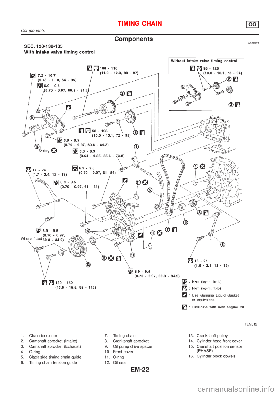
ComponentsNJEM0011
YEM012
1. Chain tensioner
2. Camshaft sprocket (Intake)
3. Camshaft sprocket (Exhaust)
4. O-ring
5. Slack side timing chain guide
6. Timing chain tension guide7. Timing chain
8. Crankshaft sprocket
9. Oil pump drive spacer
10. Front cover
11. O-ring
12. Oil seal13. Crankshaft pulley
14. Cylinder head front cover
15. Camshaft position sensor
(PHASE)
16. Cylinder block dowels
TIMING CHAINQG
Components
EM-22