Page 2037 of 2493
11 CHECK POWER SUPPLY FOR HEATER CONTROL PANEL (A/C SWITCH)
Do approx. 12 volts exist between heater control panel harness terminal No. 7 and body ground?
NHA513
YesorNo
Ye s©GO TO 13.
No©GO TO 12.
12 CHECK CIRCUIT CONTINUITY BETWEEN HEATER CONTROL PANEL AND ECM
Check circuit continuity between heater control panel harness terminal No. 7 and ECM harness terminal No. 44.
NHA514
Continuity should exist.
If OK, check harness for short.
OK or NG
OK©Check ECM. Refer to EC-132 (QG), EC-554 (YD), ªECM Terminals and Reference
Valueº.
NG©Repair harness or connector.
TROUBLE DIAGNOSES
Magnet Clutch (Cont'd)
HA-65
Page 2038 of 2493
13 CHECK HEATER CONTROL PANEL CIRCUIT
Check circuit continuity between heater control panel harness terminal No. 8 and 18.
NHA515
Continuity should exist.
If OK, check harness for short.
OK or NG
OK©GO TO 14.
NG©Repair harness or connector.
14 CHECK CIRCUIT CONTINUITY BETWEEN ECM AND HEATER CONTROL PANEL
Check circuit continuity between ECM harness terminal No. 68 or 51 and heater control panel harness terminal No. 14 or
18.
NHA516
Continuity should exist.
If OK, check harness for short.
OK or NG
OK©GO TO 15.
NG©Repair harness or connector.
15 CHECK FAN SWITCH
Refer to HA-60.
YesorNo
Ye s©GO TO 16.
No©Replace heater control panel.
TROUBLE DIAGNOSES
Magnet Clutch (Cont'd)
HA-66
Page 2039 of 2493
16 CHECK BODY GROUND CIRCUIT
Check circuit continuity between heater control panel harness terminal No. 9 or 13 and body ground.
NHA506
Continuity should exist.
If OK, check harness for short.
OK or NG
OK©INSPECTION END
NG©Repair harness or connector.
MAGNET CLUTCH CIRCUIT (FOR YD ENGINE)NJHA0203SYMPTOM:
+Magnet clutch does not engage when A/C switch and fan
switch are ON.
1 CHECK POWER SUPPLY FOR COMPRESSOR
Disconnect compressor harness connector.
Do approx. 12 volts exist between compressor harness terminal No. 1 and body ground?
RHA794H
YesorNo
Ye s©GO TO 2.
No©Disconnect A/C relay. GO TO 3.
2 CHECK MAGNET CLUTCH COIL
OK or NG
NG©Replace magnet clutch. Refer to HA-91.
TROUBLE DIAGNOSES
Magnet Clutch (Cont'd)
HA-67
Page 2043 of 2493
11 CHECK CIRCUIT CONTINUITY BETWEEN DUAL-PRESSURE SWITCH AND HEATER CONTROL PANEL
(A/C SWITCH)
Check circuit continuity between dual-pressure switch harness terminal No. 1 and heater control panel harness terminal
No. 7.
NHA520
Continuity should exist.
If OK, check harness for short.
OK or NG
OK©GO TO 12.
NG©Repair harness or connector.
12 CHECK A/C SWITCH
Refer to HA-73.
OK or NG
OK©GO TO 13.
NG©Replace A/C switch.
13 CHECK HEATER CONTROL PANEL CIRCUIT
Check circuit continuity between heater control panel harness terminal No. 8 and No. 18.
NHA521
Continuity should exist.
If OK, check harness for short.
OK or NG
OK©GO TO 14.
NG©Repair harness or connector.
TROUBLE DIAGNOSES
Magnet Clutch (Cont'd)
HA-71
Page 2044 of 2493
14 CHECK FAN SWITCH
Refer to HA-60.
OK or NG
OK©GO TO 15.
NG©Replace fan switch.
15 CHECK BODY GROUND CIRCUIT
Check circuit continuity between heater control panel harness terminal No. 13 and body ground.
RHA778H
Continuity should exist.
If OK, check harness for short.
OK or NG
OK©INSPECTION END.
NG©Repair harness or connector.
RHA638H
ELECTRICAL COMPONENT INSPECTIONNJHA0192A/C RelayNJHA0192S01Check continuity between terminal Nos. 3 and 5.
Conditions Continuity
12V direct current supply between terminal Nos. 1 and 2 Yes
No current supply No
If NG, replace relay.
TROUBLE DIAGNOSES
Magnet Clutch (Cont'd)
HA-72
Page 2066 of 2493

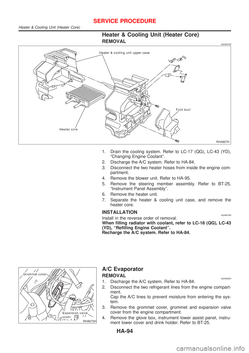
Heater & Cooling Unit (Heater Core)
REMOVALNJHA0193
RHA807H
1. Drain the cooling system. Refer to LC-17 (QG), LC-43 (YD),
ªChanging Engine Coolantº.
2. Discharge the A/C system. Refer to HA-84.
3. Disconnect the two heater hoses from inside the engine com-
partment.
4. Remove the blower unit. Refer to HA-95.
5. Remove the steering member assembly. Refer to BT-25,
ªInstrument Panel Assemblyº.
6. Remove the heater unit.
7. Separate the heater & cooling unit case, and remove the
heater core.
INSTALLATIONNJHA0194Install in the reverse order of removal.
When filling radiator with coolant, refer to LC-18 (QG), LC-43
(YD), ªRefilling Engine Coolantº.
Recharge the A/C system. Refer to HA-84.
RHA673H
A/C Evaporator
REMOVALNJHA02041. Discharge the A/C system. Refer to HA-84.
2. Disconnect the two refrigerant lines from the engine compart-
ment.
Cap the A/C lines to prevent moisture from entering the sys-
tem.
3. Remove the grommet cover, grommet and expansion valve
cover from the engine compartment.
4. Remove the glove box, instrument lower assist panel, instru-
ment lower cover and drink holder. Refer to BT-25.
SERVICE PROCEDURE
Heater & Cooling Unit (Heater Core)
HA-94
Page 2067 of 2493
RHA674H
5. Remove the five screws fixed heater & cooling unit lower
cover.
6. Slide the A/C evaporator to rear side.
7. Slide the heater & cooling unit lower cover to rear side and
then remove it.
8. Slide the A/C evaporator to the front side and then remove the
A/C evaporator.
INSTALLATIONNJHA0205Install in the reverse order of removal.
Recharge the A/C system. Refer to HA-84.
Blower Unit
REMOVALNJHA0195
RHA676HA
SERVICE PROCEDURE
A/C Evaporator (Cont'd)
HA-95
Page 2073 of 2493

5. If a leak detector detects a leak, verify at least once by blow-
ing compressed air into area of suspected leak, then repeat
check as outlined above.
6. Do not stop when one leak is found. Continue to check for
additional leaks at all system components.
If no leaks are found, perform steps7-10.
7. Start engine.
8. Set the heater A/C control as follows:
1) A/C switch ON.
2) Face mode
3) Recirculation position
4) Max cold temperature
5) Fan speed high
9. Run engine at 1,500 rpm for at least 2 minutes.
10. Turn engine off and perform leak check again following steps
4 through 6 above.
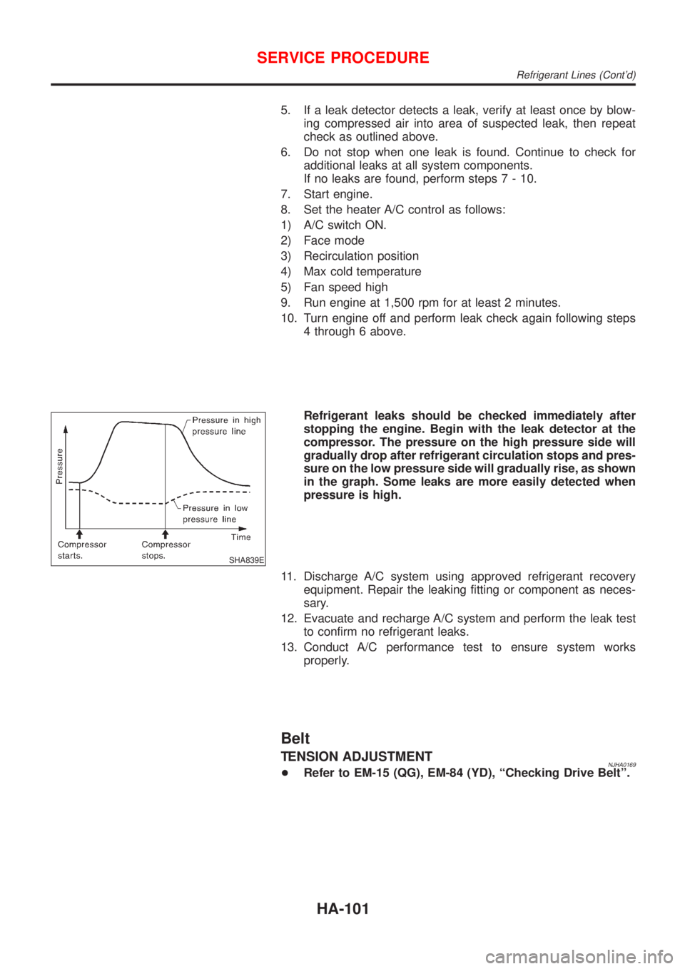
SHA839E
Refrigerant leaks should be checked immediately after
stopping the engine. Begin with the leak detector at the
compressor. The pressure on the high pressure side will
gradually drop after refrigerant circulation stops and pres-
sure on the low pressure side will gradually rise, as shown
in the graph. Some leaks are more easily detected when
pressure is high.
11. Discharge A/C system using approved refrigerant recovery
equipment. Repair the leaking fitting or component as neces-
sary.
12. Evacuate and recharge A/C system and perform the leak test
to confirm no refrigerant leaks.
13. Conduct A/C performance test to ensure system works
properly.
Belt
TENSION ADJUSTMENTNJHA0169+Refer to EM-15 (QG), EM-84 (YD), ªChecking Drive Beltº.
SERVICE PROCEDURE
Refrigerant Lines (Cont'd)
HA-101