Page 678 of 2493

3 DETECT MALFUNCTIONING PART
Check the following.
+Harness connectors F113, M169
+10A fuse
+Harness for open or short between heated oxygen sensor 1 (front) and fuse
©Repair harness or connectors.
4 CHECK GROUND CIRCUIT
1. Turn ignition switch ªOFFº.
2. Disconnect ECM harness connector.
3. Check harness continuity between heated oxygen sensor 1 (front) harness connector terminal 3 and ECM terminal 4.
Refer to wiring diagram.
Continuity should exist.
4. Also check harness for short to ground and short to power.
OK or NG
OK©GO TO 5.
NG©Repair open circuit or short to ground or short to power in harness or connectors.
5 CHECK HEATED OXYGEN SENSOR 1 HEATER (FRONT)
Refer to ªComponent Inspectionº, EC-382.
OK or NG
OK©GO TO 6.
NG©Replace heated oxygen sensor 1 (front).
6 CHECK INTERMITTENT INCIDENT
Perform ªTROUBLE DIAGNOSIS FOR INTERMITTENT INCIDENTº, EC-144.
©INSPECTION END
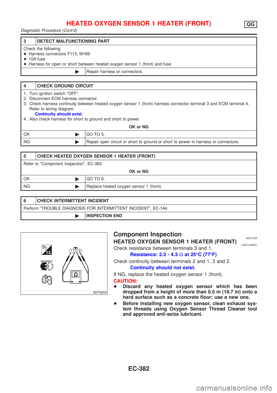
SEF935X
Component InspectionNJEC1230HEATED OXYGEN SENSOR 1 HEATER (FRONT)NJEC1230S01Check resistance between terminals 3 and 1.
Resistance: 2.3 - 4.3Wat 25ÉC (77ÉF)
Check continuity between terminals 2 and 1, 3 and 2.
Continuity should not exist.
If NG, replace the heated oxygen sensor 1 (front).
CAUTION:
+Discard any heated oxygen sensor which has been
dropped from a height of more than 0.5 m (19.7 in) onto a
hard surface such as a concrete floor; use a new one.
+Before installing new oxygen sensor, clean exhaust sys-
tem threads using Oxygen Sensor Thread Cleaner tool
and approved anti-seize lubricant.
HEATED OXYGEN SENSOR 1 HEATER (FRONT)QG
Diagnostic Procedure (Cont'd)
EC-382
Page 685 of 2493

DescriptionNJEC1240SYSTEM DESCRIPTIONNJEC1240S01
Sensor Input Signal to ECMECM func-
tionActuator
Camshaft position sensor (PHASE)
Crankshaft position sensor (POS)Engine speedHeated
oxygen
sensor 2
heater
(rear) con-
trolHeated oxygen sensor 2 heater
(rear)
The ECM performs ON/OFF control of the heated oxygen sensor 2 heater (rear) corresponding to the engine
speed.
OPERATIONNJEC1240S02
Engine condition Heated oxygen sensor 2 heater (rear)
Engine stopped OFF
Engine is running. After driving for 2 minutes at a speed
of 70 km/h (43 MPH) or moreON
Engine speed above 3,600 rpm OFF
CONSULT-II Reference Value in Data Monitor
Mode
NJEC1241Specification data are reference values.
MONITOR ITEM CONDITION SPECIFICATION
HO2S2 HTR (B1)+Engine speedBelow 3,600 rpm [After driving for 2 minutes at a
speed of 70 km/h (43 MPH) or more]ON
Above 3,600 rpm OFF
+Ignition switch ON (Engine stopped) OFF
ECM Terminals and Reference ValueNJEC1242Specification data are reference values and are measured between each terminal and ground.
CAUTION:
Do not use ECM ground terminals when measuring input/output voltage. Doing so may result in dam-
age to the ECM's transistor. Use a ground other than ECM terminals, such as the ground.
TERMI-
NAL
NO.WIRE
COLORITEM CONDITION DATA (DC Voltage)
3 W/RHeated oxygen sensor 2
heater (rear)[Engine is running]
+Engine speed is below 3,600 rpm [After driving
for 2 minutes at a speed of 70 km/h (43 MPH) or
more]0-1V
[Engine is running]
+Engine speed is above 3,600 rpm
BATTERY VOLTAGE
(11 - 14V)
[Ignition switch ªONº]
+Engine stopped
HEATED OXYGEN SENSOR 2 HEATER (REAR)QG
Description
EC-389
Page 686 of 2493
Wiring DiagramNJEC1245
YEC989
HEATED OXYGEN SENSOR 2 HEATER (REAR)QG
Wiring Diagram
EC-390
Page 687 of 2493
Diagnostic ProcedureNJEC1246
1 CHECK OVERALL FUNCTION
Without CONSULT-II
1. Start engine and drive the vehicle at over 70 km/h (43 MPH) for 2 consecutive minutes.
2. Stop vehicle and keep the engine running.
3. Set the voltmeter probe between ECM terminals 3 [HO2S2 HTR (B1) signal] and ground.
4. Check the voltage under the following conditions.
SEF241Z
OK or NG
OK©INSPECTION END
NG©GO TO 2.
2 CHECK POWER SUPPLY
1. Turn ignition switch ªOFFº.
2. Disconnect heated oxygen sensor 2 (rear) harness connector.
NEF345A
3. Turn ignition switch ªONº.
4. Check voltage between terminal 2 and ground.
SEF218W
OK or NG
OK©GO TO 4.
NG©GO TO 3.
HEATED OXYGEN SENSOR 2 HEATER (REAR)QG
Diagnostic Procedure
EC-391
Page 688 of 2493

3 DETECT MALFUNCTIONING PART
Check the following.
+Harness connectors M169, F113
+Harness for open or short between heated oxygen sensor 2 (rear) and fuse
+10A fuse
©Repair harness or connectors.
4 CHECK GROUND CIRCUIT
1. Turn ignition switch ªOFFº.
2. Disconnect ECM harness connector.
3. Check harness continuity between heated oxygen sensor 2 (rear) harness connector terminal 3 and ECM terminal 3.
Refer to wiring diagram.
Continuity should exist.
4. Also check harness for short to ground and short to power.
OK or NG
OK©GO TO 6.
NG©GO TO 5.
5 DETECT MALFUNCTIONING PART
Check the harness for open or short between heated oxygen sensor 2 heater (rear) and ECM.
©Repair open circuit or short to ground or short to power in harness or connectors.
6 CHECK HEATED OXYGEN SENSOR 2 HEATER (REAR)
Refer to ªComponent Inspectionº, EC-393.
OK or NG
OK©GO TO 7.
NG©Replace heated oxygen sensor 2 (rear).
7 CHECK INTERMITTENT INCIDENT
Perform ªTROUBLE DIAGNOSIS FOR INTERMITTENT INCIDENTº, EC-144.
©INSPECTION END
HEATED OXYGEN SENSOR 2 HEATER (REAR)QG
Diagnostic Procedure (Cont'd)
EC-392
Page 689 of 2493
SEF221W
Component InspectionNJEC1247HEATED OXYGEN SENSOR 2 HEATER (REAR)NJEC1247S01Check the following.
1. Check resistance between terminals 1 and 4.
Resistance: 2.3 - 4.3Wat 25ÉC (77ÉF)
2. Check continuity.
Terminal No. Continuity
1 and 2, 3, 4
No
4 and 1, 2, 3
If NG, replace the heated oxygen sensor 2 (rear).
CAUTION:
+Discard any heated oxygen sensor which has been
dropped from a height of more than 0.5 m (19.7 in) onto a
hard surface such as a concrete floor; use a new one.
+Before installing new oxygen sensor, clean exhaust sys-
tem threads using Oxygen Sensor Thread Cleaner tool
and approved anti-seize lubricant.
HEATED OXYGEN SENSOR 2 HEATER (REAR)QG
Component Inspection
EC-393
Page 776 of 2493

CONSULT-II Reference Value in Data Monitor
Mode
NJEC0548Specification data are reference values.
MONITOR ITEM CONDITION SPECIFICATION
LOAD SIGNAL+Ignition switch: ONRear window defogger is operating
and/or lighting switch is on.ON
Rear window defogger is not oper-
ating and lighting switch is not on.OFF
HEATER FAN SW+Ignition switch: ONHeater fan motor is operating. ON
Heater fan motor is not operating. OFF
ECM Terminals and Reference ValueNJEC0549Specification data are reference values and are measured between each terminal and ground.
CAUTION:
Do not use ECM ground terminals when measuring input/output voltage. Doing so may result in dam-
age to the ECM's transistor. Use a ground other than ECM terminals, such as the ground.
TER-
MINAL
NO.WIRE
COLORITEM CONDITION DATA (DC Voltage)
50 L/BElectric load signal
(Load switch)[Engine is running]
+Rear window defogger is operating and/or lighting
switch is onBATTERY VOLTAGE
(11 - 14V)
[Engine is running]
+Rear window defogger is not operating and lighting
switch is not onApproximately 0V
51 LG/B Heater fan motor switch[Engine is running]
+Heater fan motor is operatingApproximately 0V
[Engine is running]
+Heater fan motor is not operatingApproximately 5V
ELECTRICAL LOAD SIGNALQG
CONSULT-II Reference Value in Data Monitor Mode
EC-480
Page 783 of 2493

Diagnostic Procedure Ð Heater Control Panel
(Fan Switch) Ð
NJEC0585
1 CHECK CIRCUIT OVERALL FUNCTION
1. Start engine.
2. Heater fan motor switch ªONº.
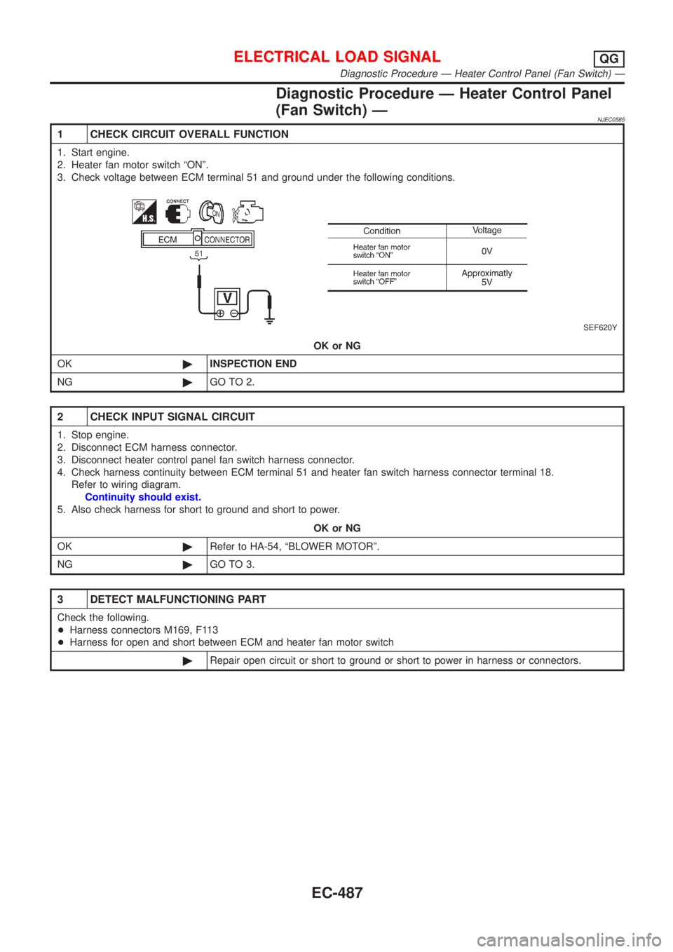
3. Check voltage between ECM terminal 51 and ground under the following conditions.
SEF620Y
OK or NG
OK©INSPECTION END
NG©GO TO 2.
2 CHECK INPUT SIGNAL CIRCUIT
1. Stop engine.
2. Disconnect ECM harness connector.
3. Disconnect heater control panel fan switch harness connector.
4. Check harness continuity between ECM terminal 51 and heater fan switch harness connector terminal 18.
Refer to wiring diagram.
Continuity should exist.
5. Also check harness for short to ground and short to power.
OK or NG
OK©Refer to HA-54, ªBLOWER MOTORº.
NG©GO TO 3.
3 DETECT MALFUNCTIONING PART
Check the following.
+Harness connectors M169, F113
+Harness for open and short between ECM and heater fan motor switch
©Repair open circuit or short to ground or short to power in harness or connectors.
ELECTRICAL LOAD SIGNALQG
Diagnostic Procedure Ð Heater Control Panel (Fan Switch) Ð
EC-487