2001 NISSAN ALMERA N16 heater
[x] Cancel search: heaterPage 301 of 2493

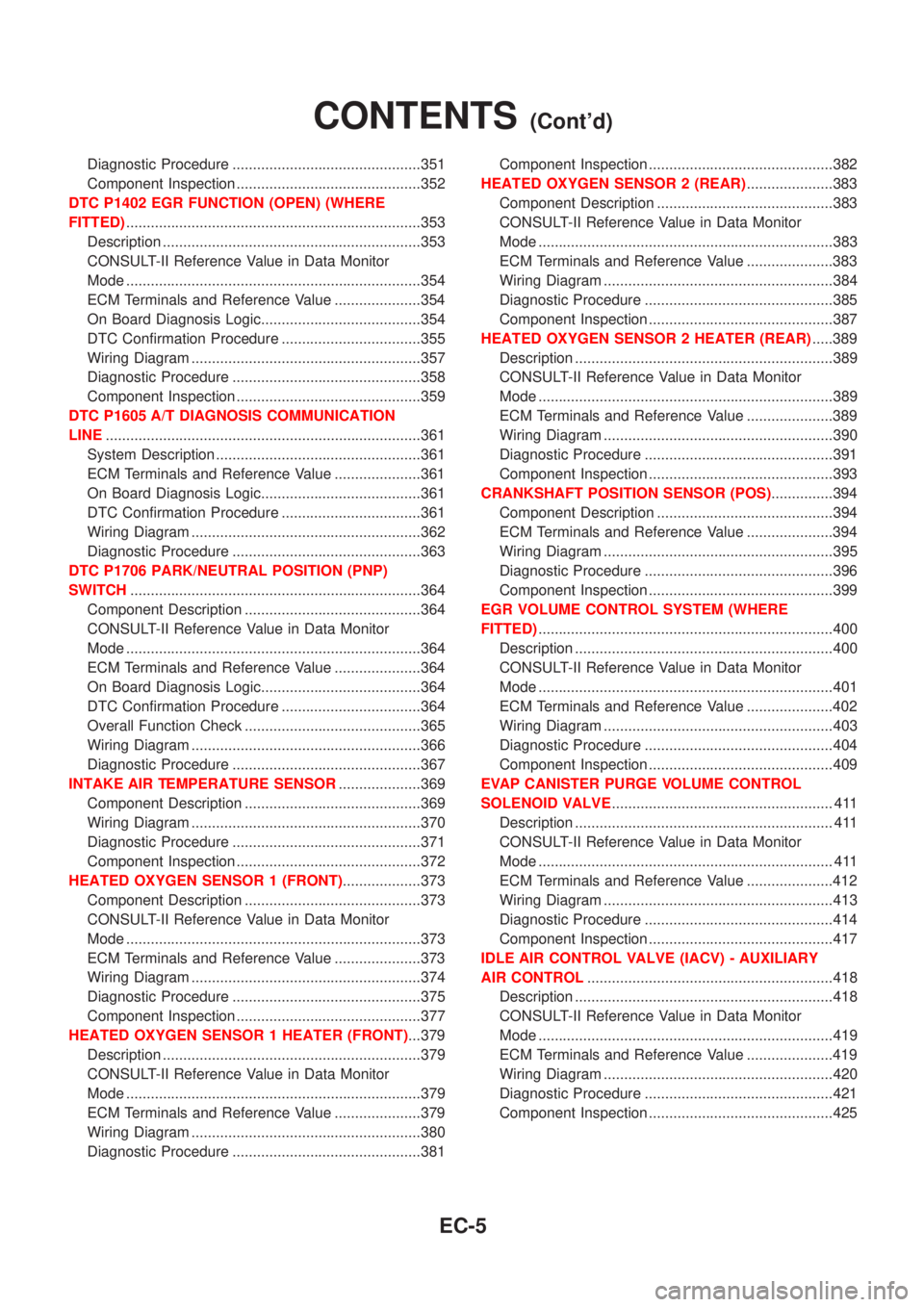
Diagnostic Procedure ..............................................351
Component Inspection .............................................352
DTC P1402 EGR FUNCTION (OPEN) (WHERE
FITTED)........................................................................353
Description ...............................................................353
CONSULT-II Reference Value in Data Monitor
Mode ........................................................................354
ECM Terminals and Reference Value .....................354
On Board Diagnosis Logic.......................................354
DTC Confirmation Procedure ..................................355
Wiring Diagram ........................................................357
Diagnostic Procedure ..............................................358
Component Inspection .............................................359
DTC P1605 A/T DIAGNOSIS COMMUNICATION
LINE.............................................................................361
System Description ..................................................361
ECM Terminals and Reference Value .....................361
On Board Diagnosis Logic.......................................361
DTC Confirmation Procedure ..................................361
Wiring Diagram ........................................................362
Diagnostic Procedure ..............................................363
DTC P1706 PARK/NEUTRAL POSITION (PNP)
SWITCH.......................................................................364
Component Description ...........................................364
CONSULT-II Reference Value in Data Monitor
Mode ........................................................................364
ECM Terminals and Reference Value .....................364
On Board Diagnosis Logic.......................................364
DTC Confirmation Procedure ..................................364
Overall Function Check ...........................................365
Wiring Diagram ........................................................366
Diagnostic Procedure ..............................................367
INTAKE AIR TEMPERATURE SENSOR....................369
Component Description ...........................................369
Wiring Diagram ........................................................370
Diagnostic Procedure ..............................................371
Component Inspection .............................................372
HEATED OXYGEN SENSOR 1 (FRONT)...................373
Component Description ...........................................373
CONSULT-II Reference Value in Data Monitor
Mode ........................................................................373
ECM Terminals and Reference Value .....................373
Wiring Diagram ........................................................374
Diagnostic Procedure ..............................................375
Component Inspection .............................................377
HEATED OXYGEN SENSOR 1 HEATER (FRONT)...379
Description ...............................................................379
CONSULT-II Reference Value in Data Monitor
Mode ........................................................................379
ECM Terminals and Reference Value .....................379
Wiring Diagram ........................................................380
Diagnostic Procedure ..............................................381Component Inspection .............................................382
HEATED OXYGEN SENSOR 2 (REAR).....................383
Component Description ...........................................383
CONSULT-II Reference Value in Data Monitor
Mode ........................................................................383
ECM Terminals and Reference Value .....................383
Wiring Diagram ........................................................384
Diagnostic Procedure ..............................................385
Component Inspection .............................................387
HEATED OXYGEN SENSOR 2 HEATER (REAR).....389
Description ...............................................................389
CONSULT-II Reference Value in Data Monitor
Mode ........................................................................389
ECM Terminals and Reference Value .....................389
Wiring Diagram ........................................................390
Diagnostic Procedure ..............................................391
Component Inspection .............................................393
CRANKSHAFT POSITION SENSOR (POS)...............394
Component Description ...........................................394
ECM Terminals and Reference Value .....................394
Wiring Diagram ........................................................395
Diagnostic Procedure ..............................................396
Component Inspection .............................................399
EGR VOLUME CONTROL SYSTEM (WHERE
FITTED)........................................................................400
Description ...............................................................400
CONSULT-II Reference Value in Data Monitor
Mode ........................................................................401
ECM Terminals and Reference Value .....................402
Wiring Diagram ........................................................403
Diagnostic Procedure ..............................................404
Component Inspection .............................................409
EVAP CANISTER PURGE VOLUME CONTROL
SOLENOID VALVE...................................................... 411
Description ............................................................... 411
CONSULT-II Reference Value in Data Monitor
Mode ........................................................................ 411
ECM Terminals and Reference Value .....................412
Wiring Diagram ........................................................413
Diagnostic Procedure ..............................................414
Component Inspection .............................................417
IDLE AIR CONTROL VALVE (IACV) - AUXILIARY
AIR CONTROL............................................................418
Description ...............................................................418
CONSULT-II Reference Value in Data Monitor
Mode ........................................................................419
ECM Terminals and Reference Value .....................419
Wiring Diagram ........................................................420
Diagnostic Procedure ..............................................421
Component Inspection .............................................425
CONTENTS(Cont'd)
EC-5
Page 302 of 2493

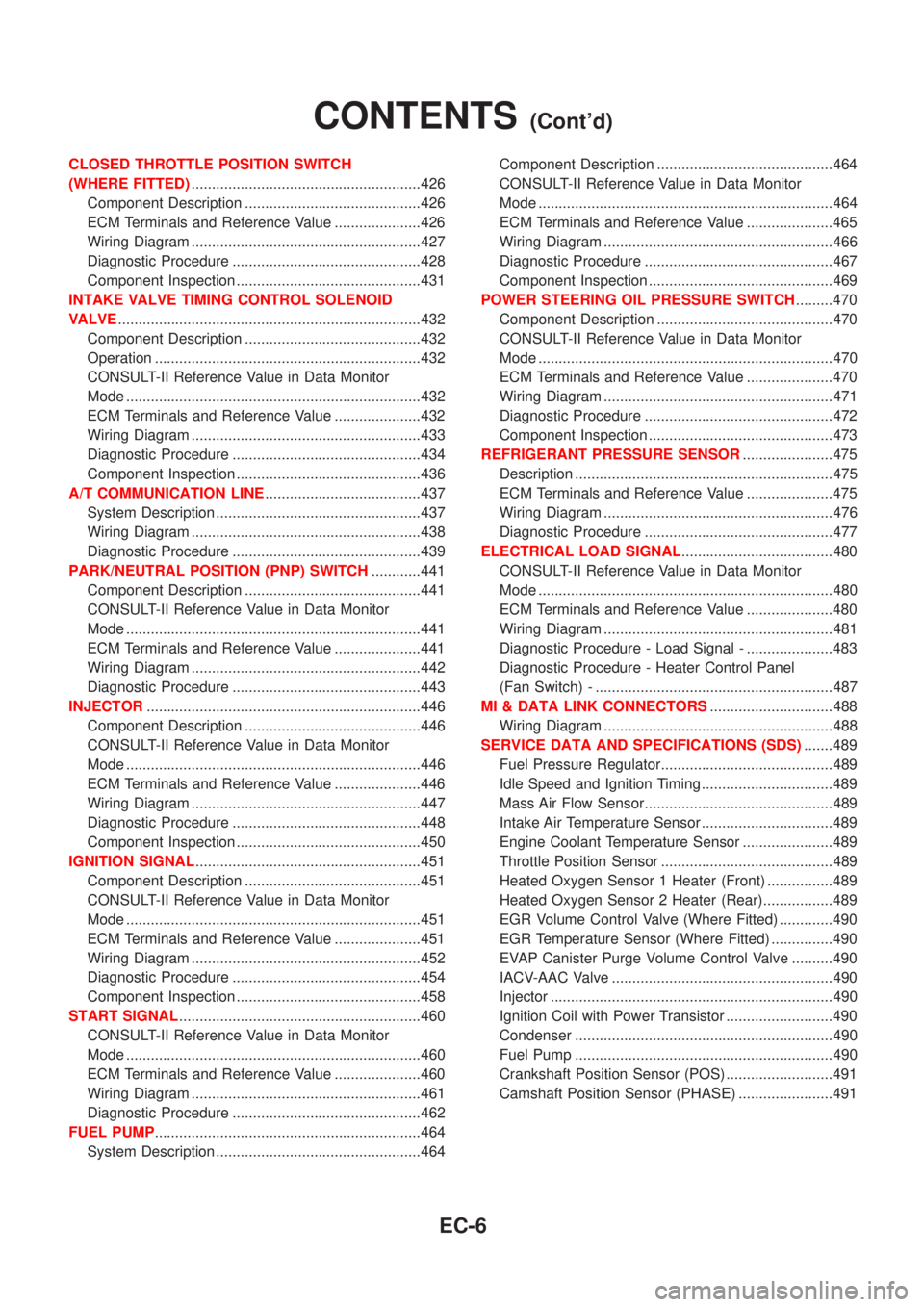
CLOSED THROTTLE POSITION SWITCH
(WHERE FITTED)........................................................426
Component Description ...........................................426
ECM Terminals and Reference Value .....................426
Wiring Diagram ........................................................427
Diagnostic Procedure ..............................................428
Component Inspection .............................................431
INTAKE VALVE TIMING CONTROL SOLENOID
VALVE..........................................................................432
Component Description ...........................................432
Operation .................................................................432
CONSULT-II Reference Value in Data Monitor
Mode ........................................................................432
ECM Terminals and Reference Value .....................432
Wiring Diagram ........................................................433
Diagnostic Procedure ..............................................434
Component Inspection .............................................436
A/T COMMUNICATION LINE......................................437
System Description ..................................................437
Wiring Diagram ........................................................438
Diagnostic Procedure ..............................................439
PARK/NEUTRAL POSITION (PNP) SWITCH............441
Component Description ...........................................441
CONSULT-II Reference Value in Data Monitor
Mode ........................................................................441
ECM Terminals and Reference Value .....................441
Wiring Diagram ........................................................442
Diagnostic Procedure ..............................................443
INJECTOR...................................................................446
Component Description ...........................................446
CONSULT-II Reference Value in Data Monitor
Mode ........................................................................446
ECM Terminals and Reference Value .....................446
Wiring Diagram ........................................................447
Diagnostic Procedure ..............................................448
Component Inspection .............................................450
IGNITION SIGNAL.......................................................451
Component Description ...........................................451
CONSULT-II Reference Value in Data Monitor
Mode ........................................................................451
ECM Terminals and Reference Value .....................451
Wiring Diagram ........................................................452
Diagnostic Procedure ..............................................454
Component Inspection .............................................458
START SIGNAL...........................................................460
CONSULT-II Reference Value in Data Monitor
Mode ........................................................................460
ECM Terminals and Reference Value .....................460
Wiring Diagram ........................................................461
Diagnostic Procedure ..............................................462
FUEL PUMP.................................................................464
System Description ..................................................464Component Description ...........................................464
CONSULT-II Reference Value in Data Monitor
Mode ........................................................................464
ECM Terminals and Reference Value .....................465
Wiring Diagram ........................................................466
Diagnostic Procedure ..............................................467
Component Inspection .............................................469
POWER STEERING OIL PRESSURE SWITCH.........470
Component Description ...........................................470
CONSULT-II Reference Value in Data Monitor
Mode ........................................................................470
ECM Terminals and Reference Value .....................470
Wiring Diagram ........................................................471
Diagnostic Procedure ..............................................472
Component Inspection .............................................473
REFRIGERANT PRESSURE SENSOR......................475
Description ...............................................................475
ECM Terminals and Reference Value .....................475
Wiring Diagram ........................................................476
Diagnostic Procedure ..............................................477
ELECTRICAL LOAD SIGNAL.....................................480
CONSULT-II Reference Value in Data Monitor
Mode ........................................................................480
ECM Terminals and Reference Value .....................480
Wiring Diagram ........................................................481
Diagnostic Procedure - Load Signal - .....................483
Diagnostic Procedure - Heater Control Panel
(Fan Switch) - ..........................................................487
MI & DATA LINK CONNECTORS..............................488
Wiring Diagram ........................................................488
SERVICE DATA AND SPECIFICATIONS (SDS).......489
Fuel Pressure Regulator..........................................489
Idle Speed and Ignition Timing ................................489
Mass Air Flow Sensor..............................................489
Intake Air Temperature Sensor ................................489
Engine Coolant Temperature Sensor ......................489
Throttle Position Sensor ..........................................489
Heated Oxygen Sensor 1 Heater (Front) ................489
Heated Oxygen Sensor 2 Heater (Rear).................489
EGR Volume Control Valve (Where Fitted) .............490
EGR Temperature Sensor (Where Fitted) ...............490
EVAP Canister Purge Volume Control Valve ..........490
IACV-AAC Valve ......................................................490
Injector .....................................................................490
Ignition Coil with Power Transistor ..........................490
Condenser ...............................................................490
Fuel Pump ...............................................................490
Crankshaft Position Sensor (POS) ..........................491
Camshaft Position Sensor (PHASE) .......................491
CONTENTS(Cont'd)
EC-6
Page 324 of 2493

System ChartNJEC0013
Input (Sensor) ECM Function Output (Actuator)
+Camshaft position sensor (PHASE)
+Crankshaft position sensor (POS)
+Mass air flow sensor
+Engine coolant temperature sensor
+Heated oxygen sensor 1 (front)
+Ignition switch
+Throttle position sensor
+PNP switch
+Air conditioner switch
+Knock sensor
+EGR temperature sensor*1, *4
+Battery voltage
+Power steering oil pressure switch
+Vehicle speed sensor
+Intake air temperature sensor
+Heated oxygen sensor 2 (rear)*2
+TCM (Transmission Control Module)*3
+Closed throttle position switch
+Electrical load
+Refrigerant pressure sensorFuel injection & mixture ratio control Injectors
Electronic ignition system Power transistor
Idle air control system IACV-AAC valve
Intake valve timing controlIntake valve timing control sole-
noid valve
Fuel pump control Fuel pump relay
On board diagnostic systemMalfunction indicator
(On the instrument panel)
EGR control*4 EGR volume control valve*4
Heated oxygen sensor 1/2 heater (front/
rear) controlHeated oxygen sensor 1/2 heater
(front/rear)
EVAP canister purge flow controlEVAP canister purge volume con-
trol solenoid valve
Cooling fan control Cooling fan relay
Air conditioning cut control Air conditioner relay
*1: These sensors are not used to control the engine system. They are used only for the on board diagnosis.
*2: Under normal conditions, this sensor is not for engine control operation.
*3: The DTC related to A/T will be sent to ECM.
*4: If so equipped
ENGINE AND EMISSION CONTROL OVERALL SYSTEMQG
System Chart
EC-28
Page 339 of 2493

h)Fuel pressure
i)Engine compression
j)EGR valve operation
k)Throttle valve
l)EVAP system
+On models equipped with air conditioner, checks should
be carried out while the air conditioner is ªOFFº.
+When checking idle speed on models equipped with A/T,
ignition timing and mixture ratio, checks should be carried
out while shift lever is in ªPº or ªNº position.
+When measuring ªCOº percentage, insert probe more
than 40 cm (15.7 in) into tail pipe.
+Turn off headlamps, heater blower, rear window defogger.
+On vehicles equipped with daytime light systems, set
lighting switch to the 1st position to light only small
lamps.
+Keep front wheels pointed straight ahead.
+If engine stops immediately after starting or idle condition
is unstable, perform the following to initialize IACV-AAC
valve:
a)Stop engine and wait 9 seconds.
b)Turn ignition ªONº and wait 1 second.
c)Turn ignition ªOFFº and wait 9 seconds.
+Make sure the cooling fan has stopped.
BASIC SERVICE PROCEDUREQG
Preparation (Cont'd)
EC-43
Page 356 of 2493

System Readiness Test (SRT) CodeNJEC0031S0103System Readiness Test (SRT) code is specified in Mode 1 of ISO 15031-5.
As part of an emissions test for Inspection & Maintenance (I/M), certain states require the status of SRT be
used to indicate whether the ECM has completed self-diagnosis of major emission systems and components.
Completion must be verified in order for the emissions inspection to proceed.
If a vehicle is rejected for a State emissions inspection due to one or more SRT items indicating ªINCMPº,
use the information in this Service Manual to set the SRT to ªCMPLTº.
In most cases the ECM will automatically complete its self-diagnosis cycle during normal usage, and the SRT
status will indicate ªCMPLTº for each application system. Once set as ªCMPLTº, the SRT status remains
ªCMPLTº until the self-diagnosis memory is erased.
Occasionally, certain portions of the self-diagnostic test may not be completed as a result of the customer's
normal driving pattern; the SRT will indicate ªINCMPº for these items.
NOTE:
The SRT will also indicate ªINCMPº if the self-diagnosis memory is erased for any reason or if the ECM
memory power supply is interrupted for several hours.
If, during the state emissions inspection, the SRT indicates ªCMPLTº for all test items, the inspector will con-
tinue with the emissions test. However, if the SRT indicates ªINCMPº for one or more of the SRT items the
vehicle is returned to the customer untested.
NOTE:
If MI is ªONº during the state emissions inspection, the vehicle is also returned to the customer untested even
though the SRT indicates ªCMPLTº for all test items. Therefore, it is important to check SRT (ªCMPLTº) and
DTC (No DTCs) before the inspection.
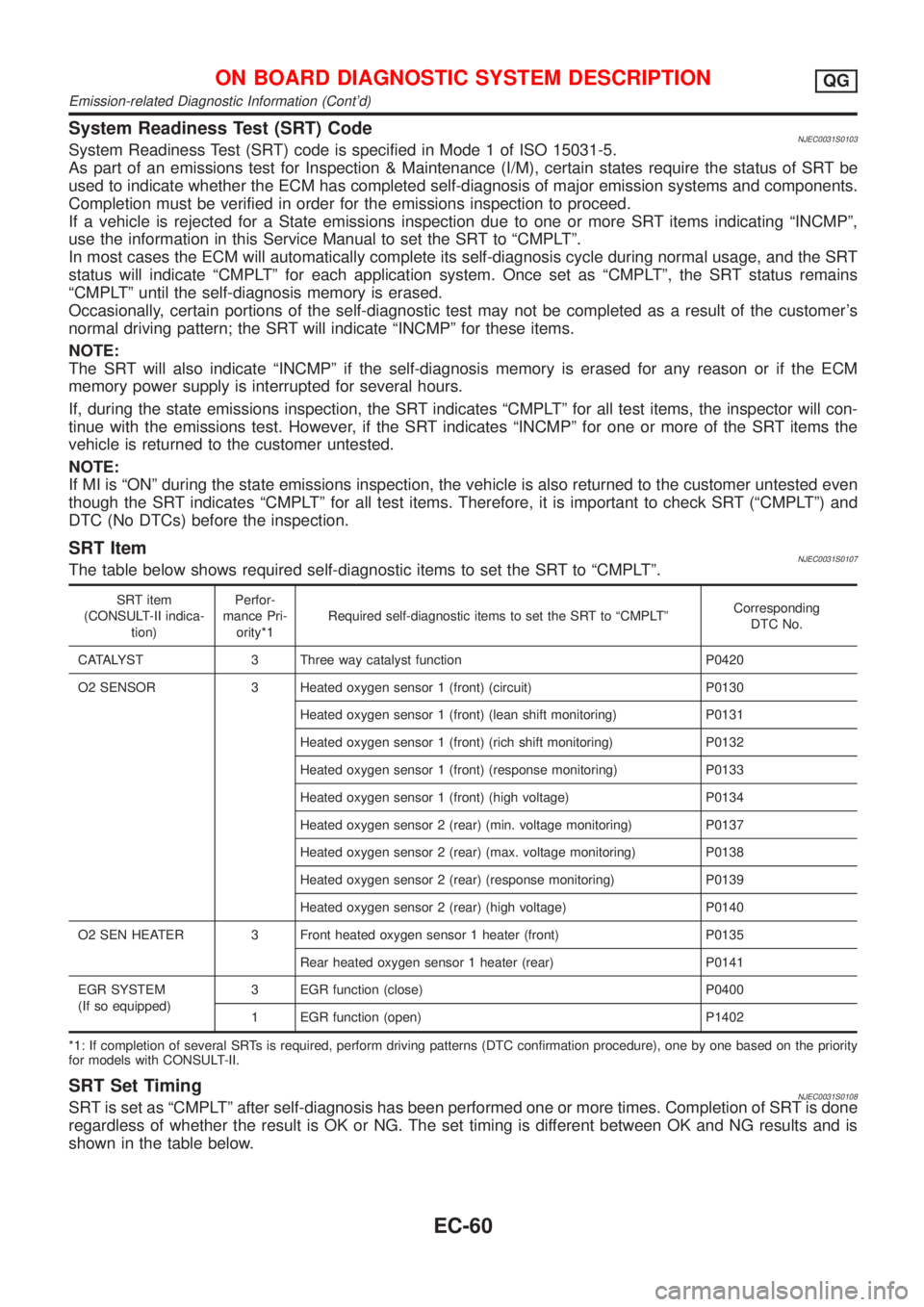
SRT ItemNJEC0031S0107The table below shows required self-diagnostic items to set the SRT to ªCMPLTº.
SRT item
(CONSULT-II indica-
tion)Perfor-
mance Pri-
ority*1Required self-diagnostic items to set the SRT to ªCMPLTºCorresponding
DTC No.
CATALYST 3 Three way catalyst function P0420
O2 SENSOR 3 Heated oxygen sensor 1 (front) (circuit) P0130
Heated oxygen sensor 1 (front) (lean shift monitoring) P0131
Heated oxygen sensor 1 (front) (rich shift monitoring) P0132
Heated oxygen sensor 1 (front) (response monitoring) P0133
Heated oxygen sensor 1 (front) (high voltage) P0134
Heated oxygen sensor 2 (rear) (min. voltage monitoring) P0137
Heated oxygen sensor 2 (rear) (max. voltage monitoring) P0138
Heated oxygen sensor 2 (rear) (response monitoring) P0139
Heated oxygen sensor 2 (rear) (high voltage) P0140
O2 SEN HEATER 3 Front heated oxygen sensor 1 heater (front) P0135
Rear heated oxygen sensor 1 heater (rear) P0141
EGR SYSTEM
(If so equipped)3 EGR function (close) P0400
1 EGR function (open) P1402
*1: If completion of several SRTs is required, perform driving patterns (DTC confirmation procedure), one by one based on the priority
for models with CONSULT-II.
SRT Set TimingNJEC0031S0108SRT is set as ªCMPLTº after self-diagnosis has been performed one or more times. Completion of SRT is done
regardless of whether the result is OK or NG. The set timing is different between OK and NG results and is
shown in the table below.
ON BOARD DIAGNOSTIC SYSTEM DESCRIPTIONQG
Emission-related Diagnostic Information (Cont'd)
EC-60
Page 362 of 2493

SRT item Self-diagnostic test itemTest value (GST display)
Test limit Application
TID CID
HO2SHeated oxygen sensor 1
(front)09H 04H Max. X
0AH 84H Min. X
0BH 04H Max. X
0CH 04H Max. X
0DH 04H Max. X
Heated oxygen sensor 2
(rear)19H 86H Min. X
1AH 86H Min. X
1BH 06H Max. X
1CH 06H Max. X
HO2S HTRHeated oxygen sensor 1
heater (front)29H 08H Max. X
2AH 88H Min. X
Heated oxygen sensor 2
heater (rear)2DH 0AH Max. X
2EH 8AH Min. X
EGR SYSTEM
(where fitted)EGR function31H 8CH Min. X
32H 8CH Min. X
33H 8CH Min. X
34H 8CH Min. X
35H 0CH Max. X
Emission-related Diagnostic Information ItemsNJEC0031S0105X: Applicable Ð: Not applicable
Items
(CONSULT-II screen terms)DTC*1 SRT codeTest value/Test
limit
(GST only)1st trip DTC*1 Reference page
NO SELF DIAGNOSTIC FAIL-
URE INDICATEDP0000ÐÐÐÐ
MAF SEN/CIRCUIT P0100 Ð Ð X EC-152
AIR TEMP SEN/CIRC P0110 Ð Ð X EC-158
COOLANT T SEN/CIRC P0115 Ð Ð X EC-163
THRTL POS SEN/CIRC P0120 Ð Ð X EC-168
HO2S1 (B1) P0130 X X X*2 EC-176
HO2S1 (B1) P0131 X X X*2 EC-183
HO2S1 (B1) P0132 X X X*2 EC-189
HO2S1 (B1) P0133 X X X*2 EC-195
HO2S1 (B1) P0134 X X X*2 EC-203
HO2S1 HTR (B1) P0135 X X X*2 EC-209
HO2S2 (B1) P0137 X X X*2 EC-214
HO2S2 (B1) P0138 X X X*2 EC-222
HO2S2 (B1) P0139 X X X*2 EC-229
ON BOARD DIAGNOSTIC SYSTEM DESCRIPTIONQG
Emission-related Diagnostic Information (Cont'd)
EC-66
Page 378 of 2493

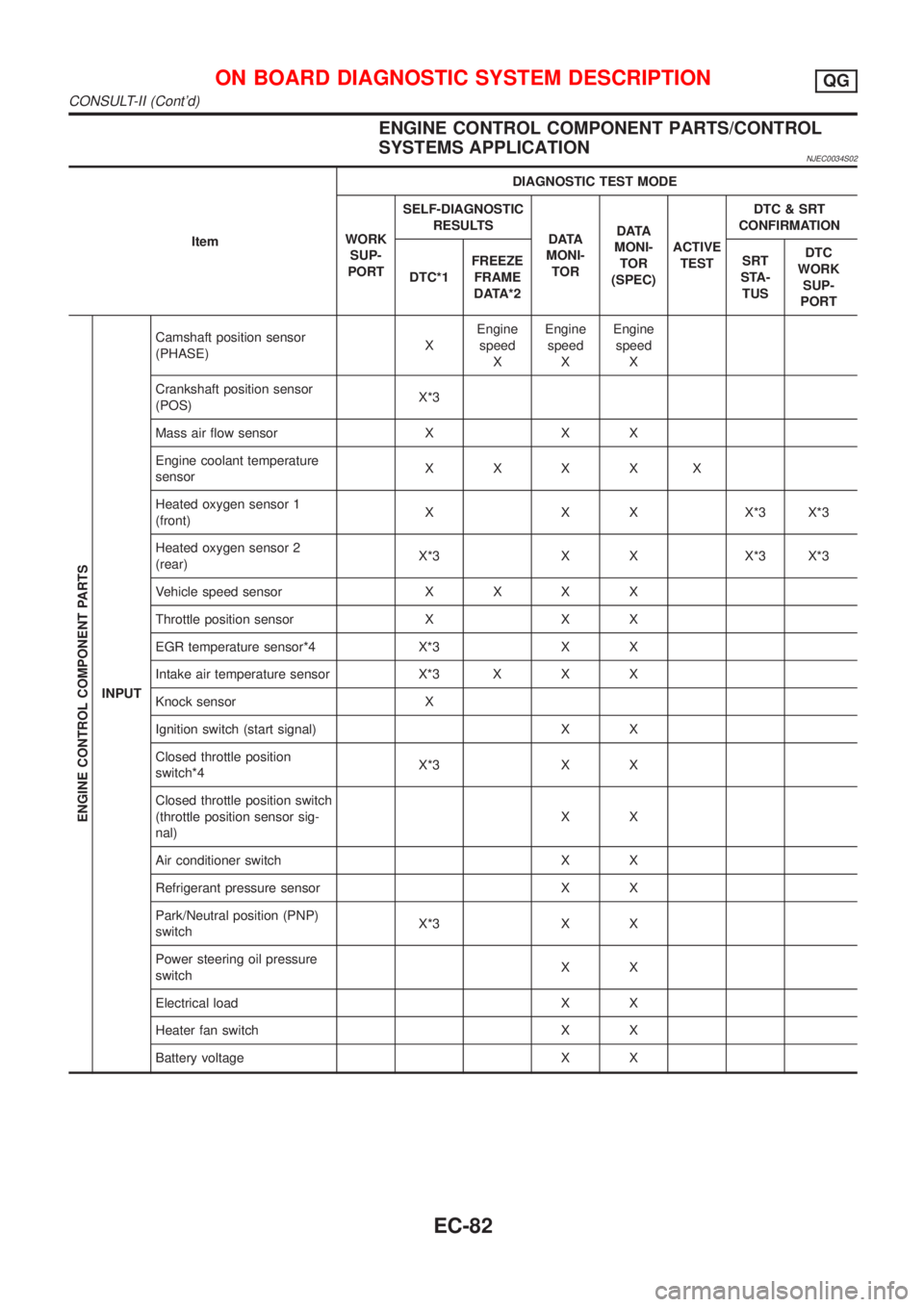
ENGINE CONTROL COMPONENT PARTS/CONTROL
SYSTEMS APPLICATION
NJEC0034S02
ItemDIAGNOSTIC TEST MODE
WORK
SUP-
PORTSELF-DIAGNOSTIC
RESULTS
D ATA
MONI-
TORD ATA
MONI-
TOR
(SPEC)ACTIVE
TESTDTC & SRT
CONFIRMATION
DTC*1FREEZE
FRAME
DATA*2SRT
STA-
TUSDTC
WORK
SUP-
PORT
ENGINE CONTROL COMPONENT PARTS
INPUTCamshaft position sensor
(PHASE)XEngine
speed
XEngine
speed
XEngine
speed
X
Crankshaft position sensor
(POS)X*3
Mass air flow sensor X X X
Engine coolant temperature
sensorXXXXX
Heated oxygen sensor 1
(front)X X X X*3 X*3
Heated oxygen sensor 2
(rear)X*3 X X X*3 X*3
Vehicle speed sensorXXXX
Throttle position sensor X X X
EGR temperature sensor*4 X*3 X X
Intake air temperature sensor X*3 X X X
Knock sensor X
Ignition switch (start signal) X X
Closed throttle position
switch*4X*3 X X
Closed throttle position switch
(throttle position sensor sig-
nal)XX
Air conditioner switch X X
Refrigerant pressure sensor X X
Park/Neutral position (PNP)
switchX*3 X X
Power steering oil pressure
switchXX
Electrical load X X
Heater fan switch X X
Battery voltage X X
ON BOARD DIAGNOSTIC SYSTEM DESCRIPTIONQG
CONSULT-II (Cont'd)
EC-82
Page 379 of 2493

ItemDIAGNOSTIC TEST MODE
WORK
SUP-
PORTSELF-DIAGNOSTIC
RESULTS
D ATA
MONI-
TORD ATA
MONI-
TOR
(SPEC)ACTIVE
TESTDTC & SRT
CONFIRMATION
DTC*1FREEZE
FRAME
DATA*2SRT
STA-
TUSDTC
WORK
SUP-
PORT
ENGINE CONTROL COMPONENT PARTS
OUT-
PUTInjectors X X X
Power transistor (Ignition tim-
ing)X*3
(misfire)XXX
IACV-AAC valve X X*3 X X X
Intake valve timing control
solenoid valveXXX
EVAP canister purge volume
control solenoid valveX*3 X X X
Air conditioner relay X X
Fuel pump relay X X X X
EGR volume control valve*4 X*3 X X X X*3
Heated oxygen sensor 1
heater (front)X*3 X X X*3
Heated oxygen sensor 2
heater (rear)X*3 X X X*3
Cooling fan X X X
Calculated load value X X X
X: Applicable
*1: This item includes 1st trip DTCs.
*2: This mode includes 1st trip freeze frame data or freeze frame data. The items appear on CONSULT-II screen in freeze frame data
mode only if a 1st trip DTC or DTC is detected. For details, refer to EC-59, EC-70.
*3: Not applicable for models without Euro-OBD system
*4: If so equipped
FUNCTIONNJEC0034S03
Diagnostic test mode Function
Work supportThis mode enables a technician to adjust some devices faster and more accurately by following the
indications on the CONSULT-II unit.
Self-diagnostic resultsSelf-diagnostic results such as 1st trip DTC, DTCs and 1st trip freeze frame data or freeze frame
data can be read and erased quickly.*1
Data monitor Input/Output data in the ECM can be read.
Data monitor (spec)Input/Output specifications of the basic fuel schedule, AFM, A/F feedback control value and the
other data monitor items can be read.
Active testDiagnostic Test Mode in which CONSULT-II drives some actuators apart from the ECMs and also
shifts some parameters in a specified range.
DTC and SRT confirmation The status of system monitoring tests and the self-diagnosis status/result can be confirmed.
ECM part number ECM part numbers can be read.
*1 The following emission-related diagnostic information is cleared when the ECM memory is erased.
1) Diagnostic trouble codes
2) 1st trip diagnostic trouble codes
3) Freeze frame data
4) 1st trip freeze frame data
ON BOARD DIAGNOSTIC SYSTEM DESCRIPTIONQG
CONSULT-II (Cont'd)
EC-83