Page 785 of 2493

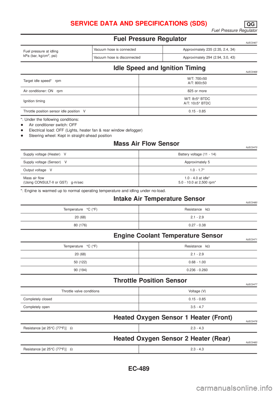
Fuel Pressure RegulatorNJEC0467
Fuel pressure at idling
kPa (bar, kg/cm2, psi)Vacuum hose is connected Approximately 235 (2.35, 2.4, 34)
Vacuum hose is disconnected Approximately 294 (2.94, 3.0, 43)
Idle Speed and Ignition TimingNJEC0468
Target idle speed* rpmM/T: 700±50
A/T: 800±50
Air conditioner: ON rpm825 or more
Ignition timingM/T: 8±5É BTDC
A/T: 10±5É BTDC
Throttle position sensor idle position V 0.15 - 0.85
*: Under the following conditions:
+Air conditioner switch: OFF
+Electrical load: OFF (Lights, heater fan & rear window defogger)
+Steering wheel: Kept in straight-ahead position
Mass Air Flow SensorNJEC0470
Supply voltage (Heater) VBattery voltage (11 - 14)
Supply voltage (Sensor) VApproximately 5
Output voltage V1.0 - 1.7*
Mass air flow
(Using CONSULT-II or GST) g´m/sec1.0 - 4.0 at idle*
5.0 - 10.0 at 2,500 rpm*
*: Engine is warmed up to normal operating temperature and idling under no-load.
Intake Air Temperature SensorNJEC0480
Temperature ÉC (ÉF) Resistance kW
20 (68) 2.1 - 2.9
80 (176) 0.27 - 0.38
Engine Coolant Temperature SensorNJEC0471
Temperature ÉC (ÉF) Resistance kW
20 (68) 2.1 - 2.9
50 (122) 0.68 - 1.00
90 (194) 0.236 - 0.260
Throttle Position SensorNJEC0477
Throttle valve conditions Voltage (V)
Completely closed0.15 - 0.85
Completely open3.5 - 4.7
Heated Oxygen Sensor 1 Heater (Front)NJEC0478
Resistance [at 25ÉC (77ÉF)]W2.3 - 4.3
Heated Oxygen Sensor 2 Heater (Rear)NJEC0483
Resistance [at 25ÉC (77ÉF)]W2.3 - 4.3
SERVICE DATA AND SPECIFICATIONS (SDS)QG
Fuel Pressure Regulator
EC-489
Page 809 of 2493
SEF434Z
Spray Pattern TestNJEC0619S051. Check spray pattern by pumping tester handle one full stroke
per second.
NG spray pattern:
Does not inject straight and strong (B in the figure).
Fuel drips (C in the figure).
Does not inject evenly (D in the figure).
2. If the spray pattern is not correct, replace injection nozzle
assembly.
Electronic Control Fuel Injection Pump
REMOVAL AND INSTALLATIONNJEC0620
JEF350Y
RemovalNJEC0620S011. Remove the parts shown below.
+Engine hood
+Engine coolant (drain)
+Engine cover
+Heater pipe under intake manifold
+Injection tubes
+Right splash cover (with undercover)
+Right front wheel
BASIC SERVICE PROCEDUREYD
Injection Tube and Injection Nozzle (Cont'd)
EC-513
Page 1973 of 2493

HEATER &
AIR CONDITIONER
SECTION
HA
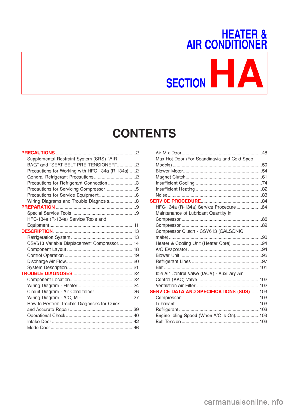
CONTENTS
PRECAUTIONS...............................................................2
Supplemental Restraint System (SRS)²AIR
BAG²and²SEAT BELT PRE-TENSIONER²...............2
Precautions for Working with HFC-134a (R-134a) .....2
General Refrigerant Precautions .................................2
Precautions for Refrigerant Connection ......................3
Precautions for Servicing Compressor ........................5
Precautions for Service Equipment .............................6
Wiring Diagrams and Trouble Diagnosis .....................8
PREPARATION...............................................................9
Special Service Tools ..................................................9
HFC-134a (R-134a) Service Tools and
Equipment .................................................................. 11
DESCRIPTION...............................................................13
Refrigeration System .................................................13
CSV613 Variable Displacement Compressor............14
Component Layout ....................................................18
Control Operation ......................................................19
Discharge Air Flow.....................................................20
System Description ....................................................21
TROUBLE DIAGNOSES................................................22
Component Location..................................................22
Wiring Diagram - Heater............................................24
Circuit Diagram - Air Conditioner...............................26
Wiring Diagram - A/C, M - .........................................27
How to Perform Trouble Diagnoses for Quick
and Accurate Repair ..................................................39
Operational Check .....................................................40
Intake Door ................................................................42
Mode Door .................................................................46Air Mix Door ...............................................................48
Max Hot Door (For Scandinavia and Cold Spec
Models) ......................................................................50
Blower Motor..............................................................54
Magnet Clutch............................................................61
Insufficient Cooling ....................................................74
Insufficient Heating ....................................................82
Noise ..........................................................................83
SERVICE PROCEDURE................................................84
HFC-134a (R-134a) Service Procedure ....................84
Maintenance of Lubricant Quantity in
Compressor ...............................................................86
Compressor ...............................................................89
Compressor Clutch - CSV613 (CALSONIC
make) .........................................................................90
Heater & Cooling Unit (Heater Core) ........................94
A/C Evaporator ..........................................................94
Blower Unit ................................................................95
Refrigerant Lines .......................................................97
Belt ...........................................................................101
Idle Air Control Valve (IACV) - Auxiliary Air
Control (AAC) Valve ................................................102
Ventilation Air Filter ..................................................102
SERVICE DATA AND SPECIFICATIONS (SDS).......103
Compressor .............................................................103
Lubricant ..................................................................103
Refrigerant ...............................................................103
Engine Idling Speed (When A/C is On)...................103
Belt Tension .............................................................103
Page 1985 of 2493

Refrigeration System
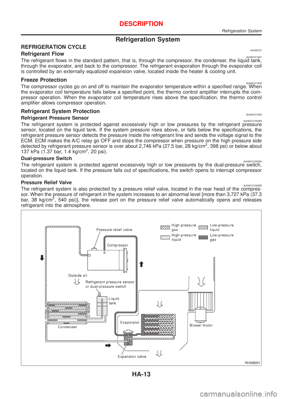
REFRIGERATION CYCLENJHA0121Refrigerant FlowNJHA0121S01The refrigerant flows in the standard pattern, that is, through the compressor, the condenser, the liquid tank,
through the evaporator, and back to the compressor. The refrigerant evaporation through the evaporator coil
is controlled by an externally equalized expansion valve, located inside the heater & cooling unit.
Freeze ProtectionNJHA0121S02The compressor cycles go on and off to maintain the evaporator temperature within a specified range. When
the evaporator coil temperature falls below a specified point, the thermo control amplifier interrupts the com-
pressor operation. When the evaporator coil temperature rises above the specification, the thermo control
amplifier allows compressor operation.
Refrigerant System ProtectionNJHA0121S03Refrigerant Pressure SensorNJHA0121S0303The refrigerant system is protected against excessively high or low pressures by the refrigerant pressure
sensor, located on the liquid tank. If the system pressure rises above, or falls below the specifications, the
refrigerant pressure sensor detects the pressure inside the refrigerant line and sends the voltage signal to the
ECM. ECM makes the A/C relay go OFF and stops the compressor when pressure on the high pressure side
detected by refrigerant pressure sensor is over about 2,746 kPa (27.5 bar, 28 kg/cm
2, 398 psi) or below about
137 kPa (1.37 bar, 1.4 kg/cm2, 20 psi).
Dual-pressure Switch
NJHA0121S0304The refrigerant system is protected against excessively high or low pressures by the dual-pressure switch,
located on the liquid tank. If the pressure falls out of specifications, the switch opens to interrupt compressor
operation.
Pressure Relief Valve
NJHA0121S0302The refrigerant system is also protected by a pressure relief valve, located in the rear head of the compres-
sor. When the pressure of refrigerant in the system increases to an abnormal level [more than 3,727 kPa (37.3
bar, 38 kg/cm
2, 540 psi)], the release port on the pressure relief valve automatically opens and releases
refrigerant into the atmosphere.
RHA682H
DESCRIPTION
Refrigeration System
HA-13
Page 1996 of 2493
Wiring Diagram Ð HeaterNJHA0202EXCEPT LHD MODELS WITH MAX HOT DOOR WITHOUT HEATED SEATNJHA0202S02
YHA361
TROUBLE DIAGNOSES
Wiring Diagram Ð Heater
HA-24
Page 1997 of 2493
LHD MODELS WITH MAX HOT DOOR WITHOUT HEATED SEATNJHA0202S03
YHA362
TROUBLE DIAGNOSES
Wiring Diagram Ð Heater (Cont'd)
HA-25
Page 2015 of 2493
RHA623H
COMPONENT DESCRIPTIONNJHA0209Intake Door MotorNJHA0209S01The intake door motor is attached to the intake unit. It rotates so
that air is drawn from inlets set by the heater control panel. Motor
rotation is conveyed to a lever which activates the intake door.
DIAGNOSTIC PROCEDURE FOR INTAKE DOOR
MOTOR CIRCUIT
NJHA0210
1 CHECK POWER SUPPLY FOR HEATER CONTROL PANEL
Do approx. 12 volts exist between heater control panel harness terminal No. 1 and body ground?
NHA495
YesorNo
Ye s©GO TO 2.
No©Check 10A (No. 15) fuse at fuse block. Refer to Sedan: EL-23 (QG), EL-0 (YD), Hatch-
back: EL-12, ªWiring Diagram Ð POWER к.
2 CHECK RECIRCULATION (REC) SWITCH
Refer to HA-45.
OK or NG
OK©GO TO 3.
NG©Replace recirculation (REC) switch.
TROUBLE DIAGNOSES
Intake Door (Cont'd)
HA-43
Page 2016 of 2493
3 CHECK GROUND CIRCUIT FOR RECIRCULATION (REC) SWITCH
Check circuit continuity between heater control panel harness terminal No. 5 and body ground.
NHA496
Continuity should exist.
If OK, check harness for short.
OK or NG
OK©GO TO 4.
Ng©Repair harness or connector.
4 CHECK POWER SUPPLY FOR INTAKE DOOR MOTOR
Do approx. 12 volts exist between intake door motor harness terminal No. 1, 2 and body ground?
NHA497
YesorNo
Ye s©Replace intake door motor.
No©GO TO 5.
TROUBLE DIAGNOSES
Intake Door (Cont'd)
HA-44