2001 NISSAN ALMERA N16 belt
[x] Cancel search: beltPage 1701 of 2493
Supplemental Restraint System (SRS) ªAIR
BAGº and ªSEAT BELT PRE-TENSIONERº
NJBR0139The Supplemental Restraint System such as ªAIR BAGº and ªSEAT BELT PRE-TENSIONERº used along with
a seat belt, helps to reduce the risk or severity of injury to the driver and front passenger for certain types of
collision. The SRS system composition which is available to NISSAN MODEL N16 is as follows (The compo-
sition varies according to the destination and optional equipment.):
+For a frontal collision
The Supplemental Restraint System consists of driver air bag module (located in the center of the steer-
ing wheel), front passenger air bag module (located on the instrument panel on passenger side), front seat
belt pre-tensioners, a diagnosis sensor unit, warning lamp, wiring harness and spiral cable.
+For a side collision
The Supplemental Restraint System consists of front side air bag module (located in the outer side of front
seat), side air bag (satellite) sensor, diagnosis sensor unit (one of components of air bags for a frontal
collision), wiring harness, warning lamp (one of components of air bags for a frontal collision).
Information necessary to service the system safely is included in theRS sectionof this Service Manual.
WARNING:
+To avoid rendering the SRS inoperative, which could increase the risk of personal injury or death
in the event of a collision which would result in air bag inflation, all maintenance should be per-
formed by an authorized NISSAN dealer.
+Improper maintenance, including incorrect removal and installation of the SRS, can lead to per-
sonal injury caused by unintentional activation of the system. For removal of Spiral Cable and Air
Bag Module, see the RS section.
+Do not use electrical test equipment on any circuit related to the SRS unless instructed to in this
Service Manual. SRS wiring harnesses can be identified by yellow harness connector.
SBR686C
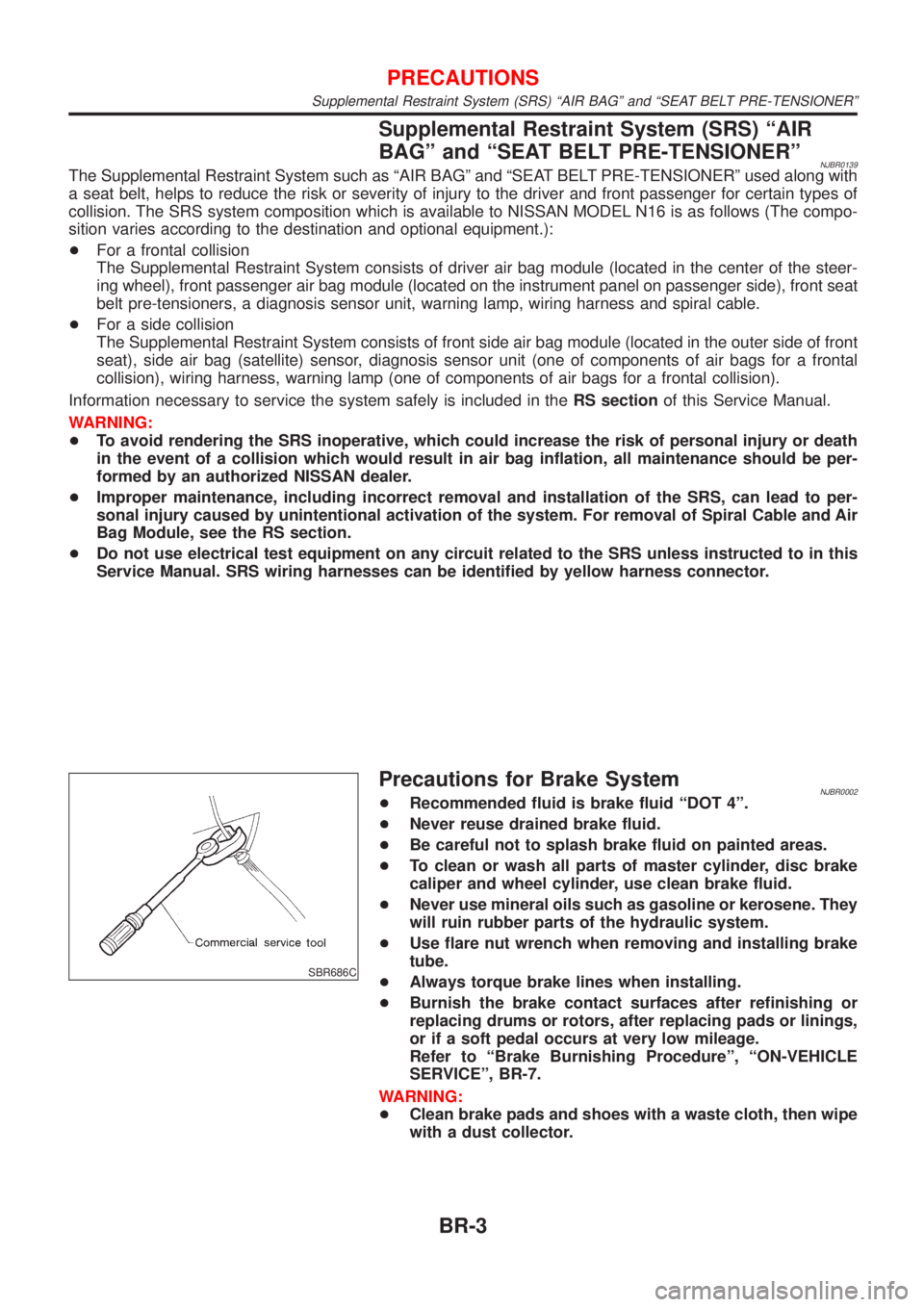
Precautions for Brake SystemNJBR0002+Recommended fluid is brake fluid ªDOT 4º.
+Never reuse drained brake fluid.
+Be careful not to splash brake fluid on painted areas.
+To clean or wash all parts of master cylinder, disc brake
caliper and wheel cylinder, use clean brake fluid.
+Never use mineral oils such as gasoline or kerosene. They
will ruin rubber parts of the hydraulic system.
+Use flare nut wrench when removing and installing brake
tube.
+Always torque brake lines when installing.
+Burnish the brake contact surfaces after refinishing or
replacing drums or rotors, after replacing pads or linings,
or if a soft pedal occurs at very low mileage.
Refer to ªBrake Burnishing Procedureº, ªON-VEHICLE
SERVICEº, BR-7.
WARNING:
+Clean brake pads and shoes with a waste cloth, then wipe
with a dust collector.
PRECAUTIONS
Supplemental Restraint System (SRS) ªAIR BAGº and ªSEAT BELT PRE-TENSIONERº
BR-3
Page 1791 of 2493
STEERING SYSTEM
SECTION
ST
CONTENTS
PRECAUTIONS...............................................................2
Supplemental Restraint System (SRS)²AIR
BAG²and²SEAT BELT PRE-TENSIONER²...............2
Precautions for Steering System .................................2
PREPARATION...............................................................3
Special Service Tools ..................................................3
Commercial Service Tool .............................................4
NOISE, VIBRATION AND HARSHNESS (NVH)
TROUBLESHOOTING.....................................................5
NVH Troubleshooting Chart.........................................5
ON-VEHICLE SERVICE..................................................6
Checking Steering Wheel Play ....................................6
Checking Neutral Position on Steering Wheel ............6
PRE-CHECKING........................................................6
CHECKING...............................................................6
Front Wheel Turning Angle ..........................................6
Checking Gear Housing Movement ............................6
Checking and Adjusting Drive Belts ............................7
Checking Steering Gear and Linkage .........................7
STEERING GEAR......................................................7
STEERING LINKAGE.................................................7
Checking Fluid Level ...................................................7
Checking Fluid Leakage ..............................................7
Bleeding Hydraulic System..........................................8
Checking Steering Wheel Turning Force ....................8
Checking Hydraulic System.........................................9
STEERING WHEEL AND STEERING COLUMN.........10
Components...............................................................10
Removal and Installation ...........................................10
STEERING WHEEL.................................................10
STEERING COLUMN............................................... 11Disassembly and Assembly .......................................13
Inspection...................................................................14
TILT MECHANISM...................................................14
POWER STEERING GEAR AND LINKAGE................15
Components...............................................................15
Removal and Installation ...........................................16
Disassembly...............................................................17
Inspection...................................................................18
BOOT.....................................................................18
RACK.....................................................................18
GEAR SUB-ASSEMBLY...........................................18
GEAR HOUSING CYLINDER....................................18
TIE-ROD OUTER AND INNER SOCKETS..................19
Assembly ...................................................................19
Adjustment .................................................................22
POWER STEERING OIL PUMP (QG ENGINE)...........24
Component Description .............................................24
POWER STEERING OIL PUMP (YD ENGINE)............25
Components...............................................................25
Pre-disassembly Inspection .......................................25
Removal and Installation ...........................................26
Disassembly...............................................................26
Inspection...................................................................27
Assembly ...................................................................28
SERVICE DATA AND SPECIFICATIONS (SDS).........29
General Specifications ...............................................29
Steering Wheel ..........................................................29
Steering Column ........................................................29
Steering Gear and Linkage .......................................30
Power Steering ..........................................................30
Page 1792 of 2493
Supplemental Restraint System (SRS) ªAIR
BAGº and ªSEAT BELT PRE-TENSIONERº
NJST0044The Supplemental Restraint System such as ªAIR BAGº and ªSEAT BELT PRE-TENSIONERº used along with
a seat belt, helps to reduce the risk or severity of injury to the driver and front passenger for certain types of
collision. The SRS system composition which is available to NISSAN MODEL N16 is as follows (The compo-
sition varies according to the destination and optional equipment.):
+For a frontal collision
The Supplemental Restraint System consists of driver air bag module (located in the center of the steer-
ing wheel), front passenger air bag module (located on the instrument panel on passenger side), front seat
belt pre-tensioners, a diagnosis sensor unit, warning lamp, wiring harness and spiral cable.
+For a side collision
The Supplemental Restraint System consists of front side air bag module (located in the outer side of front
seat), side air bag (satellite) sensor, diagnosis sensor unit (one of components of air bags for a frontal
collision), wiring harness, warning lamp (one of components of air bags for a frontal collision).
Information necessary to service the system safely is included in theRS sectionof this Service Manual.
WARNING:
+To avoid rendering the SRS inoperative, which could increase the risk of personal injury or death
in the event of a collision which would result in air bag inflation, all maintenance should be per-
formed by an authorized NISSAN dealer.
+Improper maintenance, including incorrect removal and installation of the SRS, can lead to per-
sonal injury caused by unintentional activation of the system. For removal of Spiral Cable and Air
Bag Module, see the RS section.
+Do not use electrical test equipment on any circuit related to the SRS unless instructed to in this
Service Manual. SRS wiring harnesses (except ªSEAT BELT PRE-TENSIONERº connector) can be
identified by yellow harness connector.
Precautions for Steering SystemNJST0003+Before disassembly, thoroughly clean the outside of the unit.
+Disassembly should be done in a clean work area. It is important to prevent the internal parts from
becoming contaminated by dirt or other foreign matter.
+Place disassembled parts in order, on a parts rack, for easier and proper assembly.
+Use nylon cloths or paper towels to clean the parts; common shop rags can leave lint that might
interfere with their operation.
+Before inspection or reassembly, carefully clean all parts with a general purpose, non-flammable
solvent.
+Before assembly, apply a coat of recommended power steering fluid* to hydraulic parts. Vaseline
may be applied to O-rings and seals. Do not use any grease.
+Replace all gaskets, seals and O-rings. Avoid damaging O-rings, seals and gaskets during instal-
lation. Perform functional tests whenever designated.
*: DEXRON
TMIII or equivalent. Refer to MA-20, ªFluids and Lubricantsº.
PRECAUTIONS
Supplemental Restraint System (SRS) ªAIR BAGº and ªSEAT BELT PRE-TENSIONERº
ST-2
Page 1795 of 2493
NJST0006
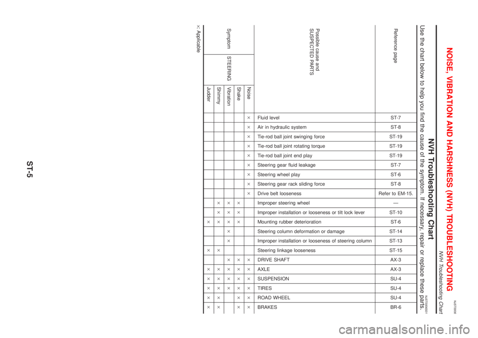
NVH Troubleshooting ChartNJST0006S01Use the chart below to help you find the cause of the symptom. If necessary, repair or replace these parts.
Reference pageST-7
ST-8
ST-19
ST-19
ST-19
ST-7
ST-6
ST-8
Refer to EM-15.
Ð
ST-10
ST-6
ST-14
ST-13
ST-15
AX-3
AX-3
SU-4
SU-4
SU-4
BR-6
Possible cause and
SUSPECTED PARTS
Fluid level
Air in hydraulic system
Tie-rod ball joint swinging force
Tie-rod ball joint rotating torque
Tie-rod ball joint end play
Steering gear fluid leakage
Steering wheel play
Steering gear rack sliding force
Drive belt looseness
Improper steering wheel
Improper installation or looseness or tilt lock lever
Mounting rubber deterioration
Steering column deformation or damage
Improper installation or looseness of steering column
Steering linkage looseness
DRIVE SHAFT
AXLE
SUSPENSION
TIRES
ROAD WHEEL
BRAKES
Symptom STEERINGNoise´´´´´´´´´ ´´´´´´
Shake´´´ ´´´´´´
Vibration´´´´´ ´´´´
Shimmy´´´ ´ ´´´´´
Judder´ ´ ´´´´´
´: Applicable
NOISE, VIBRATION AND HARSHNESS (NVH) TROUBLESHOOTING
NVH Troubleshooting Chart
ST-5
Page 1797 of 2493
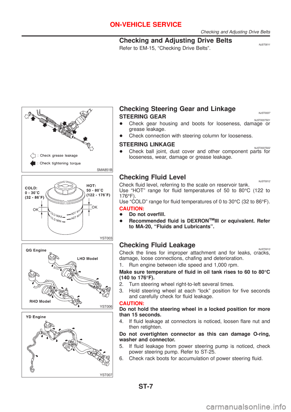
Checking and Adjusting Drive BeltsNJST0011Refer to EM-15, ªChecking Drive Beltsº.
SMA851B
Checking Steering Gear and LinkageNJST0037STEERING GEARNJST0037S01+Check gear housing and boots for looseness, damage or
grease leakage.
+Check connection with steering column for looseness.
STEERING LINKAGENJST0037S02+Check ball joint, dust cover and other component parts for
looseness, wear, damage or grease leakage.
YST003
Checking Fluid LevelNJST0012Check fluid level, referring to the scale on reservoir tank.
Use ªHOTº range for fluid temperatures of 50 to 80ÉC (122 to
176ÉF).
Use ªCOLDº range for fluid temperatures of 0 to 30ÉC (32 to 86ÉF).
CAUTION:
+Do not overfill.
+Recommended fluid is DEXRON
TMIII or equivalent. Refer
to MA-20, ªFluids and Lubricantsº.
YST006
YST007
Checking Fluid LeakageNJST0013Check the lines for improper attachment and for leaks, cracks,
damage, loose connections, chafing and deterioration.
1. Run engine between idle speed and 1,000 rpm.
Make sure temperature of fluid in oil tank rises to 60 to 80ÉC
(140 to 176ÉF).
2. Turn steering wheel right-to-left several times.
3. Hold steering wheel at each ªlockº position for five seconds
and carefully check for fluid leakage.
CAUTION:
Do not hold the steering wheel in a locked position for more
than 15 seconds.
4. If fluid leakage at connectors is noticed, loosen flare nut and
then retighten.
Do not overtighten connector as this can damage O-ring,
washer and connector.
5. If fluid leakage from power steering pump is noticed, check
power steering pump. Refer to ST-25.
6. Check rack boots for accumulation of power steering fluid.
ON-VEHICLE SERVICE
Checking and Adjusting Drive Belts
ST-7
Page 1799 of 2493

SST834-I
Checking Hydraulic SystemNJST0016Before starting, check belt tension, driving pulley and tire pressure.
1. Set Tool. Open shut-off valve. Then bleed air. Refer to ªBleed-
ing Hydraulic Systemº, ST-8.
2. Run engine at idle speed or 1,000 rpm.
Make sure temperature of fluid in tank rises to 60 to 80ÉC (140
to 176ÉF).
WARNING:
Warm up engine with shut-off valve fully opened. If engine is
started with shut-off valve closed, fluid pressure in oil pump
increases to maximum. This will raise oil temperature abnor-
mally.
3. Check pressure with steering wheel fully turned to left and right
positions with engine idling at 1,000 rpm.
CAUTION:
Do not hold the steering wheel in a locked position for more
than 15 seconds.
Oil pump maximum standard pressure:
QG15, 18 engine
8,600 - 9,200 kPa (86.0 - 92.0 bar, 88.7 - 93.8
kg/cm
2, 1,247 - 1,334 psi)
YD22 engine
8,800 - 9,400 kPa (88.0 - 94.0 bar, 88.7 - 95.8
kg/cm
2, 1,261 - 1,362 psi)
+If pressure reaches maximum operating pressure, system is
OK.
+If pressure increases above maximum operating pressure,
check power steering pump flow control valve. Refer to ST-25.
4. If power steering pressure is below the maximum operating
pressure, slowly close shut-off valve and check pressure
again.
CAUTION:
Do not close shut-off valve for more than 15 seconds.
+If pressure increases to maximum operating pressure, gear is
damaged. Refer to ªRemoval and Installationº, ST-16.
+If pressure remains below maximum operating pressure, pump
is damaged. Refer to ªDisassemblyº, ST-26.
5. After checking hydraulic system, remove Tool and add fluid as
necessary. Then completely bleed air out of system. Refer to
ST-8.
ON-VEHICLE SERVICE
Checking Hydraulic System
ST-9
Page 1821 of 2493
RESTRAINT SYSTEM
SECTION
RS
CONTENTS
SEAT BELTS...................................................................3
Precautions ..................................................................3
SUPPLEMENTAL RESTRAINT SYSTEM (SRS)
²AIR BAG²AND²SEAT BELT PRE-TENSIONER²
........3
PRECAUTION FOR SEAT BELT SERVICE..................3
Maintenance ................................................................4
Front Seat Belt.............................................................5
REMOVAL AND INSTALLATION/4-DOOR SEDAN.......5
REMOVAL AND INSTALLATION/5-DOOR
HATCHBACK
.............................................................7
REMOVAL AND INSTALLATION/3-DOOR
HATCHBACK
.............................................................9
Rear Seat Belt ........................................................... 11
REMOVAL AND INSTALLATION/4-DOOR SEDAN
WITH 2-POINT TYPE REAR CENTER SEAT BELT
.... 11
REMOVAL AND INSTALLATION/4-DOOR SEDAN
WITH 3-POINT TYPE REAR CENTER SEAT BELT
....13
REMOVAL AND INSTALLATION/HATCHBACK
WITH 3-POINT TYPE REAR CENTER SEAT
.............15
ISO Fix Child Restraint Anchor .................................18
REMOVAL AND INSTALLATION...............................18
Tether Anchor Plate ...................................................19
REMOVAL AND INSTALLATION...............................19
SUPPLEMENTAL RESTRAINT SYSTEM (SRS).........20
Precautions ................................................................20
SUPPLEMENTAL RESTRAINT SYSTEM (SRS)
²AIR BAG²AND²SEAT BELT PRE-TENSIONER²
......20
PRECAUTIONS FOR SRS²AIR BAG²AND²SEAT
BELT PRE-TENSIONER²SERVICE
...........................20
WIRING DIAGRAMS AND TROUBLE DIAGNOSIS.....20
Preparation ................................................................21
SPECIAL SERVICE TOOLS......................................21
COMMERCIAL SERVICE TOOL................................22
SRS Configuration .....................................................22
Seat Belt Pre-tensioner with Load Limiter.................23
Built-in Type Side Air Bag..........................................23
SRS Component Parts Location ...............................24
Maintenance Items ....................................................25
Diagnosis Sensor Unit ...............................................26
REMOVAL AND INSTALLATION...............................26
Front Seat Belt Pre-tensioner ....................................27
REMOVAL AND INSTALLATION...............................27
Side Air Bag (Satellite) Sensor ..................................27
REMOVAL AND INSTALLATION...............................27
Driver Air Bag Module and Spiral Cable ...................29
REMOVAL AND INSTALLATION/WITH 4-SPOKE
STEERING WHEEL
.................................................29
REMOVAL...............................................................29
INSTALLATION........................................................31
Front Passenger Air Bag Module ..............................32
REMOVAL...............................................................32
INSTALLATION........................................................33
Front Side Air Bag Module ........................................33
REMOVAL...............................................................33
INSTALLATION........................................................34
Disposal of Air Bag Module and Seat Belt Pre-
tensioner ....................................................................35
CHECKING DEPLOYMENT TOOL.............................35
DEPLOYMENT PROCEDURES FOR AIR BAG
MODULE (OUTSIDE OF VEHICLE)
...........................36
DEPLOYMENT PROCEDURES FOR SEAT BELT
PRE-TENSIONER (OUTSIDE OF VEHICLE)
..............39
DEPLOYMENT OF AIR BAG MODULE AND SEAT
BELT PRE-TENSIONER WHILE MOUNTED IN
VEHICLE
.................................................................39
DISPOSING OF AIR BAG MODULE AND SEAT
BELT PRE-TENSIONER
...........................................40
Trouble Diagnoses Introduction.................................41
DIAGNOSIS FUNCTION...........................................41
DIAGNOSIS MODE FOR CONSULT-II.......................41
HOW TO CHANGE SELF-DIAGNOSIS MODE
WITH CONSULT-II
...................................................42
HOW TO CHANGE SELF-DIAGNOSIS MODE
WITHOUT CONSULT-II
............................................42
HOW TO ERASE SELF-DIAGNOSIS RESULTS.........43
How to Perform Trouble Diagnoses for Quick
and Accurate Repair ..................................................44
INFORMATION FROM CUSTOMER..........................44
PRELIMINARY CHECK............................................44
WORK FLOW..........................................................45
Wiring Diagram - SRS -.............................................46
SEDAN MODELS.....................................................47
Page 1823 of 2493
Precautions
SUPPLEMENTAL RESTRAINT SYSTEM (SRS) ªAIR BAGº AND ªSEAT BELT
PRE-TENSIONERº
NJRS0001The Supplemental Restraint System such as ªAIR BAGº and ªSEAT BELT PRE-TENSIONERº used along with
a seat belt, helps to reduce the risk or severity of injury to the driver and front passenger for certain types of
collision. The SRS composition which is available to NISSAN MODEL N16 is as follows (The composition
varies according to the destination and optional equipment.):
+For a frontal collision
The Supplemental Restraint System consists of driver's air bag module (located in the center of the steer-
ing wheel), front passenger air bag module (located on the instrument panel on passenger side), front seat
belt pre-tensioners, a diagnosis sensor unit, warning lamp, wiring harness and spiral cable.
+For a side collision
The Supplemental Restraint System consists of front side air bag module (located in the outer side of front
seat), side air bag (satellite) sensor, diagnosis sensor unit (one of components of air bags for a frontal
collision), wiring harness, warning lamp (one of components of air bags for a frontal collision).
WARNING:
+To avoid rendering the SRS inoperative, which could increase the risk of personal injury or death
in the event of a collision which would result in air bag inflation, all maintenance should be per-
formed by an authorized NISSAN dealer.
+Improper maintenance, including incorrect removal and installation of the SRS, can lead to per-
sonal injury caused by unintentional activation of the system.
+Do not use electrical test equipment on any circuit related to the SRS unless instructed to in this
Service Manual. SRS wiring harnesses can be identified by yellow harness connector.
PRECAUTION FOR SEAT BELT SERVICENJRS0002CAUTION:
+Before removing the seat belt pre-tensioner assembly, turn the ignition switch off, disconnect both
battery cables and wait at least 3 minutes.
+Do not use electrical test equipment for seat belt pre-tensioner connector.
+After replacing or reinstalling seat belt pre-tensioner assembly, or reconnecting seat belt pre-ten-
sioner connector, check the system function. Refer to ªSRS Operation Checkº for details. (RS-49)
+Do not disassemble buckle or seat belt assembly.
+Replace anchor bolts if they are deformed or worn out.
+Never oil tongue and buckle.
+If any component of seat belt assembly is questionable, do not repair. Replace the whole seat belt
assembly.
+If webbing is cut, frayed, or damaged, replace seat belt assembly.
+When replacing seat belt assembly, use a genuine seat belt assembly.
After A CollisionNJRS0002S01WARNING:
Inspect all seat belt assemblies including retractors and attaching hardware after any collision.
NISSAN recommends that all seat belt assemblies in use during a collision be replaced unless the
collision was minor and the belts show no damage and continue to operate properly. Failure to do so
could result in serious personal injury in an accident. Seat belt assemblies not in use during a colli-
sion should also be replaced if either damage or improper operation is noted. Seat belt pre-tensioner
should be replaced even if the seat belts are not in use during a frontal collision in which the air bags
are deployed.
Replace any seat belt assembly (including anchor bolts) if:
+The seat belt was in use at the time of a collision (except for minor collisions and the belts, retractors and
buckles show no damage and continue to operate properly).
+The seat belt was damaged in an accident. (i.e. torn webbing, bent retractor or guide, etc.)
+The seat belt attaching point was damaged in an accident. Inspect the seat belt attaching area for dam-
age or distortion and repair as necessary before installing a new seat belt assembly.
+Anchor bolts are deformed or worn out.
+The seat belt pre-tensioner should be replaced even if the seat belts are not in use during the collision in
which the air bags are deployed.
SEAT BELTS
Precautions
RS-3