Page 101 of 2493

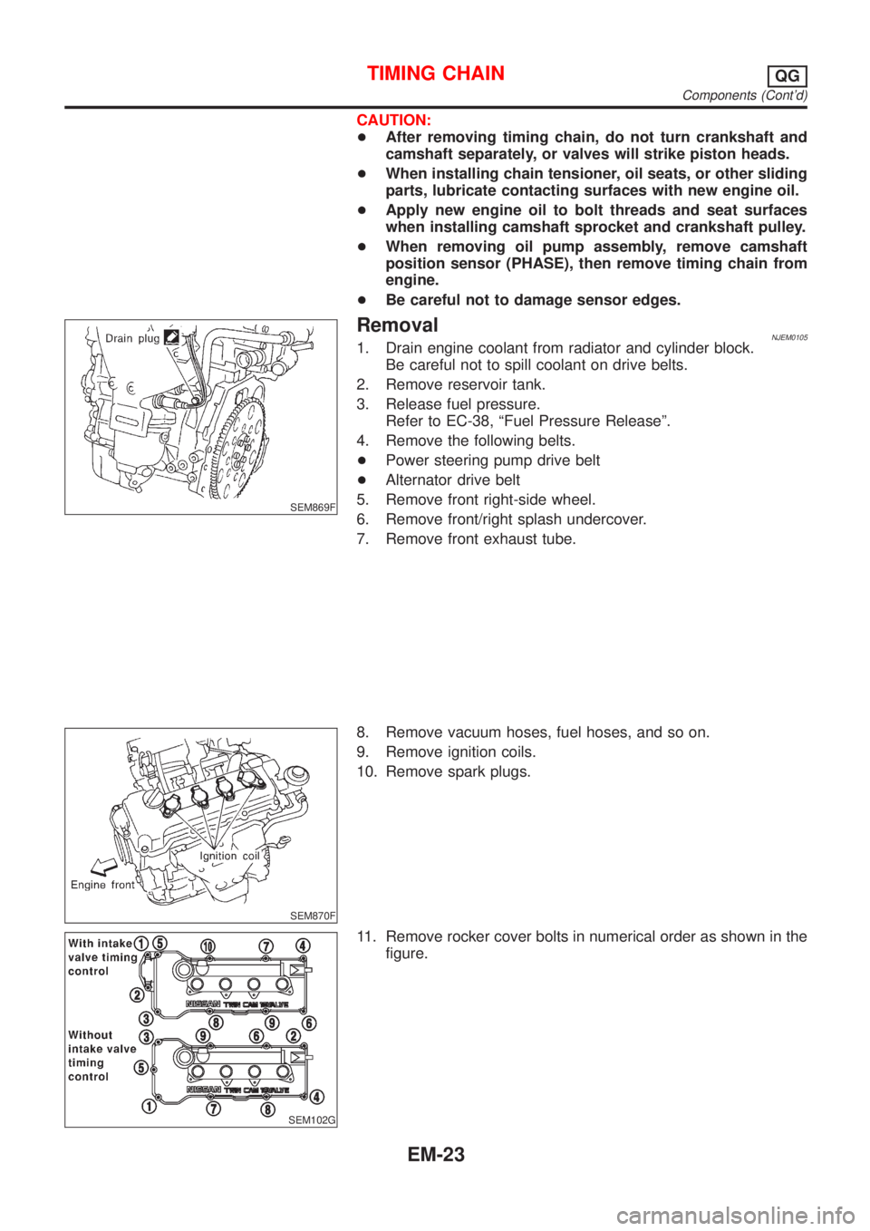
CAUTION:
+After removing timing chain, do not turn crankshaft and
camshaft separately, or valves will strike piston heads.
+When installing chain tensioner, oil seats, or other sliding
parts, lubricate contacting surfaces with new engine oil.
+Apply new engine oil to bolt threads and seat surfaces
when installing camshaft sprocket and crankshaft pulley.
+When removing oil pump assembly, remove camshaft
position sensor (PHASE), then remove timing chain from
engine.
+Be careful not to damage sensor edges.
SEM869F
RemovalNJEM01051. Drain engine coolant from radiator and cylinder block.
Be careful not to spill coolant on drive belts.
2. Remove reservoir tank.
3. Release fuel pressure.
Refer to EC-38, ªFuel Pressure Releaseº.
4. Remove the following belts.
+Power steering pump drive belt
+Alternator drive belt
5. Remove front right-side wheel.
6. Remove front/right splash undercover.
7. Remove front exhaust tube.
SEM870F
8. Remove vacuum hoses, fuel hoses, and so on.
9. Remove ignition coils.
10. Remove spark plugs.
SEM102G
11. Remove rocker cover bolts in numerical order as shown in the
figure.
TIMING CHAINQG
Components (Cont'd)
EM-23
Page 108 of 2493
SEM887F
24. Install cylinder head front cover.
+Apply liquid gasket to cylinder head front cover.
+Use Genuine Liquid Gasket or equivalent.
SEM889F
25. Install camshaft position sensor (PHASE).
SEM888F
26. Before installing rocker cover, apply a continuous bead of liq-
uid gasket to mating surface of cylinder head.
SEM105G
27. Install rocker cover with rocker cover gasket and tighten bolts
in numerical order as shown in the figure.
28. Install spark plugs.
29. Install ignition coils.
30. Install front exhaust tube.
31. Install front/right splash undercover.
32. Install front right-side wheel.
33. Drive belts.
For adjusting drive belt deflection, refer to EM-15, ªCheckingº.
34. Reinstall parts in reverse order of removal.
TIMING CHAINQG
Installation (Cont'd)
EM-30
Page 109 of 2493
SEM909F
ReplacementNJEM0015VALVE OIL SEALNJEM0015S011. Remove rocker cover.
2. Remove camshaft.
3. Remove valve spring. Refer to EM-36.
4. Remove valve oil seal with Tool.
Piston concerned should be set at TDC to prevent valve from
falling.
SEM910F
5. Apply new engine oil to new valve oil seal and install it with
Tool.
SEM911F
FRONT OIL SEALNJEM0015S021. Remove the following parts:
+Engine under cover
+RH engine side cover
+Alternator and power steering drive belts
+Crankshaft pulley
2. Remove front oil seal from front cover.
+Be careful not to scratch front cover.
SEM715A
SEM912F
3. Apply new engine oil to new oil seal and install it using a suit-
able tool.
+Install new oil seal in the direction shown.
OIL SEALQG
Replacement
EM-31
Page 112 of 2493

CAUTION:
+When installing camshaft and oil seal, lubricate contacting
surfaces with new engine oil.
+When tightening cylinder head bolts, camshaft sprocket
bolts and camshaft bracket bolts, lubricate bolt threads
and seat surfaces with new engine oil.
+Attach tags to valve lifters so as not to mix them up.
SEM869F
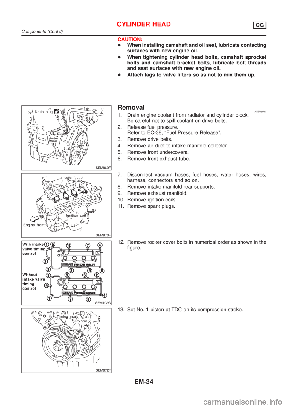
RemovalNJEM00171. Drain engine coolant from radiator and cylinder block.
Be careful not to spill coolant on drive belts.
2. Release fuel pressure.
Refer to EC-38, ªFuel Pressure Releaseº.
3. Remove drive belts.
4. Remove air duct to intake manifold collector.
5. Remove front undercovers.
6. Remove front exhaust tube.
SEM870F
7. Disconnect vacuum hoses, fuel hoses, water hoses, wires,
harness, connectors and so on.
8. Remove intake manifold rear supports.
9. Remove exhaust manifold.
10. Remove ignition coils.
11. Remove spark plugs.
SEM102G
12. Remove rocker cover bolts in numerical order as shown in the
figure.
SEM872F
13. Set No. 1 piston at TDC on its compression stroke.
CYLINDER HEADQG
Components (Cont'd)
EM-34
Page 126 of 2493
SEM887F
10. Install cylinder head front cover.
+Apply liquid gasket to cylinder head front cover.
+Use Genuine Liquid Gasket or equivalent.
SEM889F
11. Install camshaft position sensor (PHASE).
SEM888F
12. Before installing rocker cover, apply a continuous bead of liq-
uid gasket to mating surface of cylinder head.
SEM105G
13. Install rocker cover with rocker cover gasket and tighten bolts
in numerical order as shown in the figure.
14. Install spark plugs.
15. Install ignition coils.
16. Install exhaust manifold.
17. Install intake manifold rear supports.
18. Connect vacuum hoses, fuel hoses, water hose, wire, harness,
connectors and so on.
19. Install front exhaust tube.
20. Install front undercovers.
21. Install air duct to intake manifold collector.
22. Drive belts.
For adjusting drive belt deflection, refer to ªCheckingº, EM-15.
23. Reinstall parts in reverse order of removal.
CYLINDER HEADQG
Installation (Cont'd)
EM-48
Page 128 of 2493

WARNING:
+Position vehicle on a flat and solid surface.
+Place chocks at front and back of rear wheels.
+Do not remove engine until exhaust system has com-
pletely cooled off, otherwise, you may burn yourself
and/or fire may break out in fuel line.
+Before disconnecting fuel hose, release pressure.
Refer to EC-38, ªFuel Pressure Releaseº.
+Be sure to lift engine and transaxle in a safe manner.
+For engines not equipped with engine slingers, attach
proper slingers and bolts described in PARTS CATALOG.
CAUTION:
+When lifting engine, be sure to clear surrounding parts.
Use special care near accelerator wire casing, brake lines
and brake master cylinder.
+When lifting the engine, always use engine slingers in a
safe manner.
+When removing drive shaft, be careful not to damage
grease seal of transaxle.
+Before separating engine and transaxle, remove crank-
shaft position sensor (POS) from the cylinder block
assembly.
+Always be extra careful not to damage edge of crankshaft
position sensor (POS), or signal plate teeth.
Engine cannot be removed separately from transaxle. Remove
engine with transaxle as an assembly.
REMOVALNJEM0022S011. Drain coolant from radiator and cylinder block. Refer to LC-17,
ªChanging Engine Coolantº.
2. Remove coolant reservoir tank and bracket.
3. Drain engine oil.
4. Remove battery and battery tray.
5. Remove air cleaner and air duct.
6. Remove drive belts.
7. Remove alternator and air conditioner compressor from
engine.
8. Remove power steering oil pump from engine and position
aside.
Power steering oil pump does not need to be disconnected
from power steering tubes.
ENGINE ASSEMBLYQG
Removal and Installation (Cont'd)
EM-50
Page 142 of 2493

General SpecificationsNJEM0028
EngineQG15DE QG18DE
ClassificationGasoline
Cylinder arrangement4, in-line
Displacement
cm
3(cu in)1,497 (91.35) 1,769 (107.94)
Bore´stroke
mm (in)73.6´88.0 (2.898´3.465) 80.0´88.0 (3.150´3.465)
Valve arrangementDOHC
Firing order1-3-4-2
Number of piston ringsCompression 2
Oil 1
Number of main bearings5
Compression ratio9.5 (9.9*)
*: For QG15DE for Europe
EM120
abcde f
Valve timingQG18DE 222É 236É 0É (20É) 56É (36É) þ2É 44É
QG15DE 222É 222É 0É 42É þ2É 44É
( ): Valve timing control ON
Compression PressureNJEM0029Unit: kPa (bar, kg/cm2, psi)/350 rpm
Standard1,324 (13.24, 13.5, 192)
1,372 (13.720, 13.99, 198.9)*
Minimum1,128 (11.28, 11.5, 164)
1,176 (11.759, 11.99, 170.5)*
Difference limit between cylinders 98 (0.98, 1.0, 14)
*: For QG15DE
Belt DeflectionNJEM0045Unit: mm (in)
Applied engineUsed belt deflection
Deflection of new belt
LimitDeflection after adjust-
ment
AlternatorWith air conditioner
compressorQG15´18DE 8.1 (0.319)5.3 - 5.7
(0.209 - 0.224)4.5 - 5.0
(0.177 - 0.197)
Without air conditioner
compressorQG15´18DE 10.2 (0.402)6.5 - 7.0
(0.256 - 0.276)5.5 - 6.1
(0.217 - 0.240)
SERVICE DATA AND SPECIFICATIONS (SDS)QG
General Specifications
EM-64
Page 143 of 2493
Applied engineUsed belt deflection
Deflection of new belt
LimitDeflection after adjust-
ment
Power steering oil pumpQG15DE 8.5 (0.335)5.2 - 5.8
(0.205 - 0.228)4.6 - 5.2
(0.181 - 0.205)
QG18DE 7.1 (0.280)4.4 - 4.9
(0.173 - 0.193)3.9 - 4.4
(0.154 - 0.173)
Applied pushing force 98 N (10 kg, 22 lb)
Spark PlugNJEM0046
NGK Champion
TypeStandard BKR5E-11 RC10YC4
Hot BKR4E-11 Ð
Cold BKR6E-11 Ð
Plug gap mm (in)1.0 - 1.1 (0.039 - 0.043)
Cylinder HeadNJEM0030Unit: mm (in)
Standard Limit
Head surface flatness Less than 0.03 (0.0012) 0.1 (0.004)
Height 117.8 - 118.0 (4.638 - 4.646) Ð
SERVICE DATA AND SPECIFICATIONS (SDS)QG
Belt Deflection (Cont'd)
EM-65