2001 NISSAN ALMERA N16 check engine
[x] Cancel search: check enginePage 209 of 2493
JEM149G
JEM166G
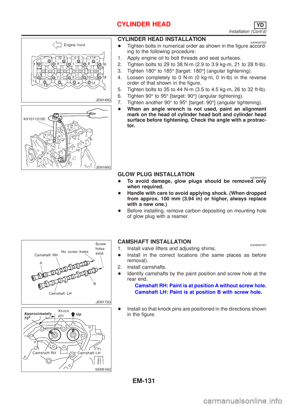
CYLINDER HEAD INSTALLATIONNJEM0067S05+Tighten bolts in numerical order as shown in the figure accord-
ing to the following procedure:
1. Apply engine oil to bolt threads and seat surfaces.
2. Tighten bolts to 29 to 38 N´m (2.9 to 3.9 kg-m, 21 to 28 ft-lb).
3. Tighten 180É to 185É [target: 180É] (angular tightening).
4. Loosen completely to 0 N´m (0 kg-m, 0 in-lb) in the reverse
order of that shown in the figure.
5. Tighten bolts to 35 to 44 N´m (3.5 to 4.5 kg-m, 26 to 32 ft-lb).
6. Tighten 90É to 95É [target: 90É] (angular tightening).
7. Tighten another 90É to 95É [target: 90É] (angular tightening).
+When an angle wrench is not used, paint an alignment
mark on the head of cylinder head bolt and cylinder head
surface before tightening. Check the angle with a protrac-
tor.
GLOW PLUG INSTALLATIONNJEM0067S06+To avoid damage, glow plugs should be removed only
when required.
+Handle with care to avoid applying shock. (When dropped
from approx. 100 mm (3.94 in) or higher, always replace
with a new one.)
+Before installing, remove carbon depositing on mounting hole
of glow plug with a reamer.
JEM173G
CAMSHAFT INSTALLATIONNJEM0067S071. Install valve lifters and adjusting shims.
+Install in the correct locations (the same places as before
removal).
2. Install camshafts.
+Identify camshafts by the paint position and screw hole at the
rear end.
Camshaft RH: Paint is at position A without screw hole.
Camshaft LH: Paint is at position B with screw hole.
SEM516G
+Install so that knock pins are positioned in the directions shown
in the figure.
CYLINDER HEADYD
Installation (Cont'd)
EM-131
Page 210 of 2493

JEM175G
3. Install camshaft brackets.
+Install correctly, identifying brackets by the journal No. and
front mark on top surface.
JEM160G
4. Tighten bolts in the order shown in the figure according to the
following procedure:
a. Tighten to 2.0 N´m (0.2 kg-m, 17 in-lb).
+Make sure camshaft thrusting parts (on rear side) securely fit
in their mating parts on the cylinder head.
b. Tighten to 6 N´m (0.6 kg-m, 52 in-lb).
c. Tighten to 12 to 13 N´m (1.2 to 1.4 kg-m, 9 to 10 ft-lb).
5. Install camshaft sprockets.
+Camshaft sprockets are commonly used for RH and LH.
+Align camshaft sprocket and dowel pin on camshaft, and
install.
+Holding the hexagonal part of camshaft with a wrench, tighten
bolt securing camshaft sprocket.
6. Before installing spill tube after installing secondary timing
chain, check and adjust valve clearance. Refer to EM-132,
ªValve Clearanceº.
7. Hereafter, install in the reverse order of removal.
JEM176G
Valve ClearanceNJEM0068CHECKINGNJEM0068S01Check valve clearance while engine is cold and not running.
1. Set the No. 1 piston to TDC on its compression stroke.
+Turn crankshaft pulley clockwise so that the knock pin on cam-
shaft LH faces straight above. (No position indicator, etc. is
provided on the crankshaft pulley.)
JEM177G
2. Put an alignment mark with paint, etc. on the crankshaft pul-
ley and on the oil pump as an angle indicator.
CYLINDER HEADYD
Installation (Cont'd)
EM-132
Page 211 of 2493
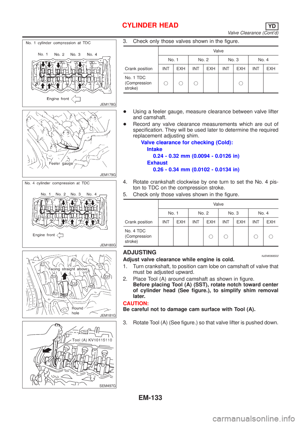
JEM178G
3. Check only those valves shown in the figure.
Crank positionValve
No. 1 No. 2 No. 3 No. 4
INT EXH INT EXH INT EXH INT EXH
No. 1 TDC
(Compression
stroke)jjj j
JEM179G
+Using a feeler gauge, measure clearance between valve lifter
and camshaft.
+Record any valve clearance measurements which are out of
specification. They will be used later to determine the required
replacement adjusting shim.
Valve clearance for checking (Cold):
Intake
0.24 - 0.32 mm (0.0094 - 0.0126 in)
Exhaust
0.26 - 0.34 mm (0.0102 - 0.0134 in)
JEM180G
4. Rotate crankshaft clockwise by one turn to set the No. 4 pis-
ton to TDC on the compression stroke.
5. Check only those valves shown in the figure.
Crank positionValve
No. 1 No. 2 No. 3 No. 4
INT EXH INT EXH INT EXH INT EXH
No. 4 TDC
(Compression
stroke)jj jj
JEM181G
ADJUSTINGNJEM0068S02Adjust valve clearance while engine is cold.
1. Turn crankshaft, to position cam lobe on camshaft of valve that
must be adjusted upward.
2. Place Tool (A) around camshaft as shown in figure.
Before placing Tool (A) (SST), rotate notch toward center
of cylinder head (See figure.), to simplify shim removal
later.
CAUTION:
Be careful not to damage cam surface with Tool (A).
SEM497G
3. Rotate Tool (A) (See figure.) so that valve lifter is pushed down.
CYLINDER HEADYD
Valve Clearance (Cont'd)
EM-133
Page 216 of 2493
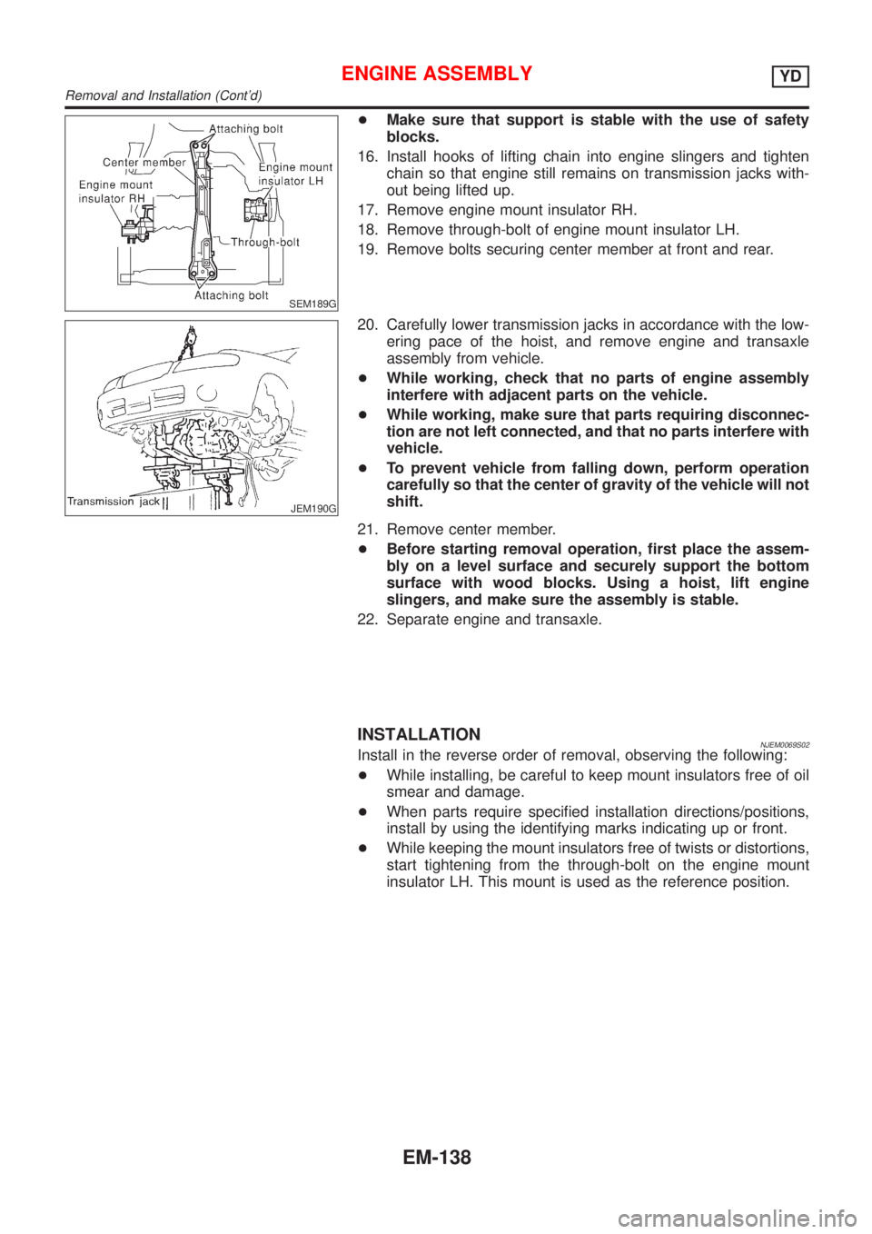
SEM189G
+Make sure that support is stable with the use of safety
blocks.
16. Install hooks of lifting chain into engine slingers and tighten
chain so that engine still remains on transmission jacks with-
out being lifted up.
17. Remove engine mount insulator RH.
18. Remove through-bolt of engine mount insulator LH.
19. Remove bolts securing center member at front and rear.
JEM190G
20. Carefully lower transmission jacks in accordance with the low-
ering pace of the hoist, and remove engine and transaxle
assembly from vehicle.
+While working, check that no parts of engine assembly
interfere with adjacent parts on the vehicle.
+While working, make sure that parts requiring disconnec-
tion are not left connected, and that no parts interfere with
vehicle.
+To prevent vehicle from falling down, perform operation
carefully so that the center of gravity of the vehicle will not
shift.
21. Remove center member.
+Before starting removal operation, first place the assem-
bly on a level surface and securely support the bottom
surface with wood blocks. Using a hoist, lift engine
slingers, and make sure the assembly is stable.
22. Separate engine and transaxle.
INSTALLATIONNJEM0069S02Install in the reverse order of removal, observing the following:
+While installing, be careful to keep mount insulators free of oil
smear and damage.
+When parts require specified installation directions/positions,
install by using the identifying marks indicating up or front.
+While keeping the mount insulators free of twists or distortions,
start tightening from the through-bolt on the engine mount
insulator LH. This mount is used as the reference position.
ENGINE ASSEMBLYYD
Removal and Installation (Cont'd)
EM-138
Page 219 of 2493
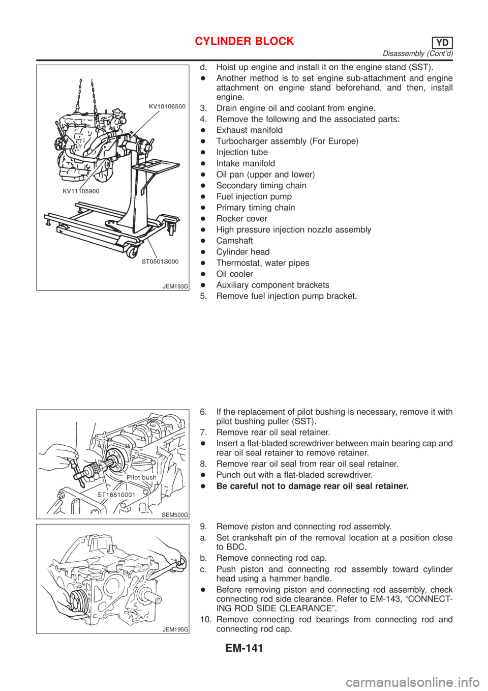
JEM193G
d. Hoist up engine and install it on the engine stand (SST).
+Another method is to set engine sub-attachment and engine
attachment on engine stand beforehand, and then, install
engine.
3. Drain engine oil and coolant from engine.
4. Remove the following and the associated parts:
+Exhaust manifold
+Turbocharger assembly (For Europe)
+Injection tube
+Intake manifold
+Oil pan (upper and lower)
+Secondary timing chain
+Fuel injection pump
+Primary timing chain
+Rocker cover
+High pressure injection nozzle assembly
+Camshaft
+Cylinder head
+Thermostat, water pipes
+Oil cooler
+Auxiliary component brackets
5. Remove fuel injection pump bracket.
SEM500G
6. If the replacement of pilot bushing is necessary, remove it with
pilot bushing puller (SST).
7. Remove rear oil seal retainer.
+Insert a flat-bladed screwdriver between main bearing cap and
rear oil seal retainer to remove retainer.
8. Remove rear oil seal from rear oil seal retainer.
+Punch out with a flat-bladed screwdriver.
+Be careful not to damage rear oil seal retainer.
JEM195G
9. Remove piston and connecting rod assembly.
a. Set crankshaft pin of the removal location at a position close
to BDC.
b. Remove connecting rod cap.
c. Push piston and connecting rod assembly toward cylinder
head using a hammer handle.
+Before removing piston and connecting rod assembly, check
connecting rod side clearance. Refer to EM-143, ªCONNECT-
ING ROD SIDE CLEARANCEº.
10. Remove connecting rod bearings from connecting rod and
connecting rod cap.
CYLINDER BLOCKYD
Disassembly (Cont'd)
EM-141
Page 223 of 2493
SEM599A
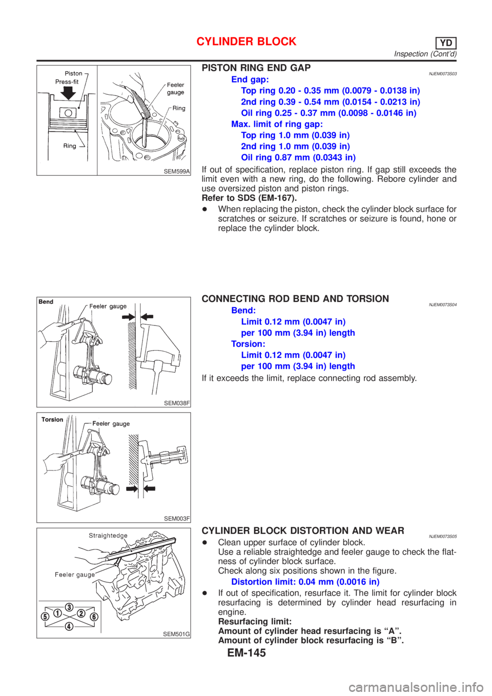
PISTON RING END GAPNJEM0073S03End gap:
Top ring 0.20 - 0.35 mm (0.0079 - 0.0138 in)
2nd ring 0.39 - 0.54 mm (0.0154 - 0.0213 in)
Oil ring 0.25 - 0.37 mm (0.0098 - 0.0146 in)
Max. limit of ring gap:
Top ring 1.0 mm (0.039 in)
2nd ring 1.0 mm (0.039 in)
Oil ring 0.87 mm (0.0343 in)
If out of specification, replace piston ring. If gap still exceeds the
limit even with a new ring, do the following. Rebore cylinder and
use oversized piston and piston rings.
Refer to SDS (EM-167).
+When replacing the piston, check the cylinder block surface for
scratches or seizure. If scratches or seizure is found, hone or
replace the cylinder block.
SEM038F
SEM003F
CONNECTING ROD BEND AND TORSIONNJEM0073S04Bend:
Limit 0.12 mm (0.0047 in)
per 100 mm (3.94 in) length
Torsion:
Limit 0.12 mm (0.0047 in)
per 100 mm (3.94 in) length
If it exceeds the limit, replace connecting rod assembly.
SEM501G
CYLINDER BLOCK DISTORTION AND WEARNJEM0073S05+Clean upper surface of cylinder block.
Use a reliable straightedge and feeler gauge to check the flat-
ness of cylinder block surface.
Check along six positions shown in the figure.
Distortion limit: 0.04 mm (0.0016 in)
+If out of specification, resurface it. The limit for cylinder block
resurfacing is determined by cylinder head resurfacing in
engine.
Resurfacing limit:
Amount of cylinder head resurfacing is ªAº.
Amount of cylinder block resurfacing is ªBº.
CYLINDER BLOCKYD
Inspection (Cont'd)
EM-145
Page 233 of 2493
JEM224G
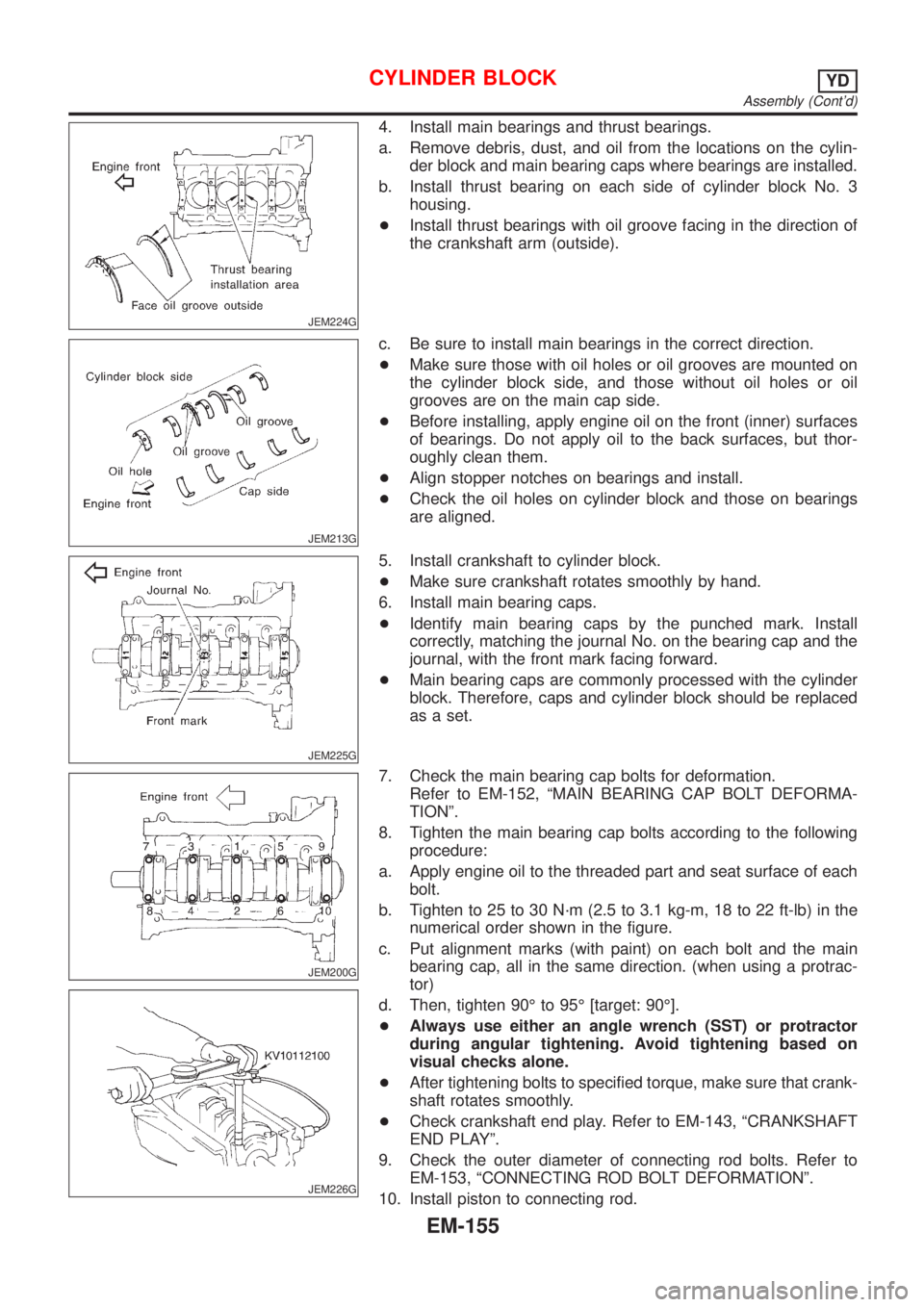
4. Install main bearings and thrust bearings.
a. Remove debris, dust, and oil from the locations on the cylin-
der block and main bearing caps where bearings are installed.
b. Install thrust bearing on each side of cylinder block No. 3
housing.
+Install thrust bearings with oil groove facing in the direction of
the crankshaft arm (outside).
JEM213G
c. Be sure to install main bearings in the correct direction.
+Make sure those with oil holes or oil grooves are mounted on
the cylinder block side, and those without oil holes or oil
grooves are on the main cap side.
+Before installing, apply engine oil on the front (inner) surfaces
of bearings. Do not apply oil to the back surfaces, but thor-
oughly clean them.
+Align stopper notches on bearings and install.
+Check the oil holes on cylinder block and those on bearings
are aligned.
JEM225G
5. Install crankshaft to cylinder block.
+Make sure crankshaft rotates smoothly by hand.
6. Install main bearing caps.
+Identify main bearing caps by the punched mark. Install
correctly, matching the journal No. on the bearing cap and the
journal, with the front mark facing forward.
+Main bearing caps are commonly processed with the cylinder
block. Therefore, caps and cylinder block should be replaced
as a set.
JEM200G
JEM226G
7. Check the main bearing cap bolts for deformation.
Refer to EM-152, ªMAIN BEARING CAP BOLT DEFORMA-
TIONº.
8. Tighten the main bearing cap bolts according to the following
procedure:
a. Apply engine oil to the threaded part and seat surface of each
bolt.
b. Tighten to 25 to 30 N´m (2.5 to 3.1 kg-m, 18 to 22 ft-lb) in the
numerical order shown in the figure.
c. Put alignment marks (with paint) on each bolt and the main
bearing cap, all in the same direction. (when using a protrac-
tor)
d. Then, tighten 90É to 95É [target: 90É].
+Always use either an angle wrench (SST) or protractor
during angular tightening. Avoid tightening based on
visual checks alone.
+After tightening bolts to specified torque, make sure that crank-
shaft rotates smoothly.
+Check crankshaft end play. Refer to EM-143, ªCRANKSHAFT
END PLAYº.
9. Check the outer diameter of connecting rod bolts. Refer to
EM-153, ªCONNECTING ROD BOLT DEFORMATIONº.
10. Install piston to connecting rod.
CYLINDER BLOCKYD
Assembly (Cont'd)
EM-155
Page 234 of 2493
JEM229G
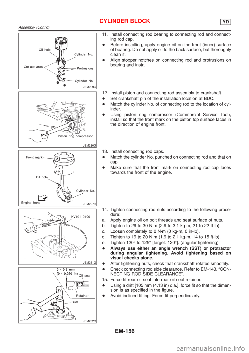
11. Install connecting rod bearing to connecting rod and connect-
ing rod cap.
+Before installing, apply engine oil on the front (inner) surface
of bearing. Do not apply oil to the back surface, but thoroughly
clean it.
+Align stopper notches on connecting rod and protrusions on
bearing and install.
JEM230G
12. Install piston and connecting rod assembly to crankshaft.
+Set crankshaft pin of the installation location at BDC.
+Match the cylinder No. of connecting rod to the location of cyl-
inder.
+Using piston ring compressor (Commercial Service Tool),
install so that the front mark on the piston top surface faces in
the direction of engine front.
JEM227G
13. Install connecting rod caps.
+Match the cylinder No. punched on connecting rod and that on
cap.
+Make sure that the front mark on connecting rod cap faces
towards the front of the engine.
JEM231G
JEM232G
14. Tighten connecting rod nuts according to the following proce-
dure:
a. Apply engine oil on bolt threads and seat surface of nuts.
b. Tighten to 29 to 30 N´m (2.9 to 3.1 kg-m, 21 to 22 ft-lb).
c. Loosen completely to 0 N´m (0 kg-m, 0 in-lb).
d. Tighten to 19 to 20 N´m (1.9 to 2.1 kg-m, 14 to 15 ft-lb).
e. Tighten 120É to 125É [target: 120É]. (angular tightening)
+Always use either an angle wrench (SST) or protractor
during angular tightening. Avoid tightening based on
visual checks alone.
+After tightening nuts, check that crankshaft rotates smoothly.
+Check connecting rod side clearance. Refer to EM-143, ªCON-
NECTING ROD SIDE CLEARANCEº.
15. Force fit rear oil seal into rear oil seal retainer.
+Using a drift [105 mm (4.13 in) dia.], force fit so that the dimen-
sion is as specified in the figure.
+Avoid inclined fitting. Force fit perpendicularly.
CYLINDER BLOCKYD
Assembly (Cont'd)
EM-156