Page 1564 of 2493
SAT065F
9. Remove inter body from upper body.
10. Remove pilot filter, separating plate and gaskets from upper
body.
SAT870J
11. Check to see that steel balls are properly positioned in inter
body and then remove them.
+Be careful not to lose steel balls.
SAT871J
12. Check to see that steel balls are properly positioned in upper
body and then remove them.
+Be careful not to lose steel balls.
SAT872J
INSPECTIONNJAT0131Lower and Upper BodiesNJAT0131S01+Check to see that retainer plates are properly positioned in
lower body.
SAT321G
+Check to see that retainer plates are properly positioned in
upper body.
REPAIR FOR COMPONENT PARTS
Control Valve Assembly (Cont'd)
AT-378
Page 1566 of 2493
SAT072F
b. Install upper separating gasket, upper inter separating gasket
and upper separating plate in order shown in illustration.
+Always use new gaskets.
SAT073F
c. Install reamer boltsFfrom bottom of upper body. Using reamer
bolts as guides, install separating plate and gaskets as a seat.
SAT074F
d. Install pilot filter.
SAT870J
e. Place inter body as shown in the illustration. Install steel balls
in their proper positions.
SAT076F
f. Install inter body on upper body using reamer boltsFas
guides.
+Be careful not to dislocate or drop steel balls.
REPAIR FOR COMPONENT PARTS
Control Valve Assembly (Cont'd)
AT-380
Page 1712 of 2493
RemovalNJBR0139
NBR351
1. Reservoir cap
2. Oil filter
3. Reservoir tank4. Seal
5. Cylinder body
6. Secondary piston assembly7. Primary piston assembly
8. Stopper cap
CAUTION:
Be careful not to splash brake fluid on painted areas; it may
cause paint damage. If brake fluid is splashed on painted
areas, wash it away with water immediately.
1. Connect a vinyl tube to air bleeder valve.
2. Drain brake fluid from each air bleeder valve, depressing brake
pedal to empty fluid from master cylinder.
3. Remove brake pipe flare nuts.
4. Remove master cylinder mounting nuts.
MASTER CYLINDER (NABCO)
Removal
BR-14
Page 1715 of 2493
RemovalNJBR0117
SBR766E
1. Reservoir cap
2. Oil filter (ABS models only)
3. Reservoir tank
4. Seal5. Cylinder body
6. Elastic pin
7. Piston stopper pin8. Secondary piston assembly
9. Primary piston assembly
10. Circlip
CAUTION:
Be careful not to splash brake fluid on painted areas; it may
cause paint damage. If brake fluid is splashed on painted
areas, wash it away with water immediately.
1. Connect a vinyl tube to front caliper air bleeder valve.
2. Drain brake fluid from each front caliper air bleeder valve,
depressing brake pedal to empty fluid from master cylinder.
3. Remove brake pipe flare nuts.
4. Remove master cylinder mounting nuts.
SBR231E
DisassemblyNJBR01181. Drive out elastic pin from cylinder body.
2. Remove reservoir tank and seals.
MASTER CYLINDER [BOSCH (NABCO)]
Removal
BR-17
Page 1973 of 2493

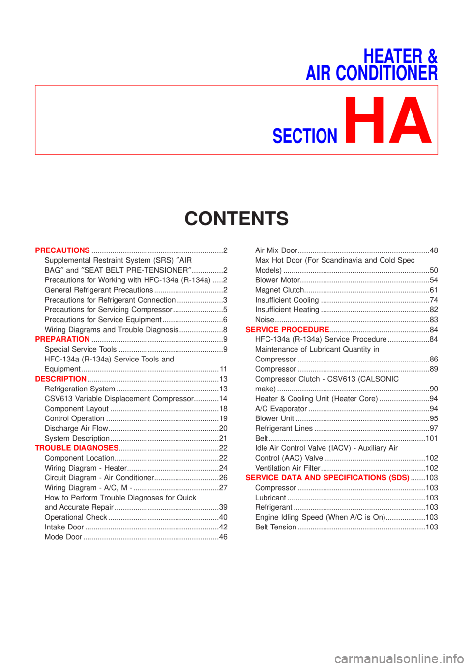
HEATER &
AIR CONDITIONER
SECTION
HA
CONTENTS
PRECAUTIONS...............................................................2
Supplemental Restraint System (SRS)²AIR
BAG²and²SEAT BELT PRE-TENSIONER²...............2
Precautions for Working with HFC-134a (R-134a) .....2
General Refrigerant Precautions .................................2
Precautions for Refrigerant Connection ......................3
Precautions for Servicing Compressor ........................5
Precautions for Service Equipment .............................6
Wiring Diagrams and Trouble Diagnosis .....................8
PREPARATION...............................................................9
Special Service Tools ..................................................9
HFC-134a (R-134a) Service Tools and
Equipment .................................................................. 11
DESCRIPTION...............................................................13
Refrigeration System .................................................13
CSV613 Variable Displacement Compressor............14
Component Layout ....................................................18
Control Operation ......................................................19
Discharge Air Flow.....................................................20
System Description ....................................................21
TROUBLE DIAGNOSES................................................22
Component Location..................................................22
Wiring Diagram - Heater............................................24
Circuit Diagram - Air Conditioner...............................26
Wiring Diagram - A/C, M - .........................................27
How to Perform Trouble Diagnoses for Quick
and Accurate Repair ..................................................39
Operational Check .....................................................40
Intake Door ................................................................42
Mode Door .................................................................46Air Mix Door ...............................................................48
Max Hot Door (For Scandinavia and Cold Spec
Models) ......................................................................50
Blower Motor..............................................................54
Magnet Clutch............................................................61
Insufficient Cooling ....................................................74
Insufficient Heating ....................................................82
Noise ..........................................................................83
SERVICE PROCEDURE................................................84
HFC-134a (R-134a) Service Procedure ....................84
Maintenance of Lubricant Quantity in
Compressor ...............................................................86
Compressor ...............................................................89
Compressor Clutch - CSV613 (CALSONIC
make) .........................................................................90
Heater & Cooling Unit (Heater Core) ........................94
A/C Evaporator ..........................................................94
Blower Unit ................................................................95
Refrigerant Lines .......................................................97
Belt ...........................................................................101
Idle Air Control Valve (IACV) - Auxiliary Air
Control (AAC) Valve ................................................102
Ventilation Air Filter ..................................................102
SERVICE DATA AND SPECIFICATIONS (SDS).......103
Compressor .............................................................103
Lubricant ..................................................................103
Refrigerant ...............................................................103
Engine Idling Speed (When A/C is On)...................103
Belt Tension .............................................................103
Page 2074 of 2493
Idle Air Control Valve (IACV) Ð Auxiliary Air
Control (AAC) Valve
INSPECTIONNJHA0199+Refer to EC-313 (QG), ªSystem Descriptionº.
RHA680H
Ventilation Air Filter
FUNCTIONNJHA0171Air inside passenger compartment is kept clean at either recircula-
tion or fresh mode by installing ventilation air filter into cooling unit.
SHA868E
REPLACEMENT TIMINGNJHA0172Replace ventilation air filter.
Refer to MA-8, ªPERIODIC MAINTENANCEº.
Caution label is fixed inside the glove box.
RHA681H
REPLACEMENT PROCEDURENJHA0173+Remove glove box.
+Remove filter cover.
+Take out the ventilation air filter from blower unit.
+Replace with new one and reinstall on blower unit.
+Reinstall glove box.
SERVICE PROCEDURE
Idle Air Control Valve (IACV) Ð Auxiliary Air Control (AAC) Valve
HA-102