Page 1042 of 2493

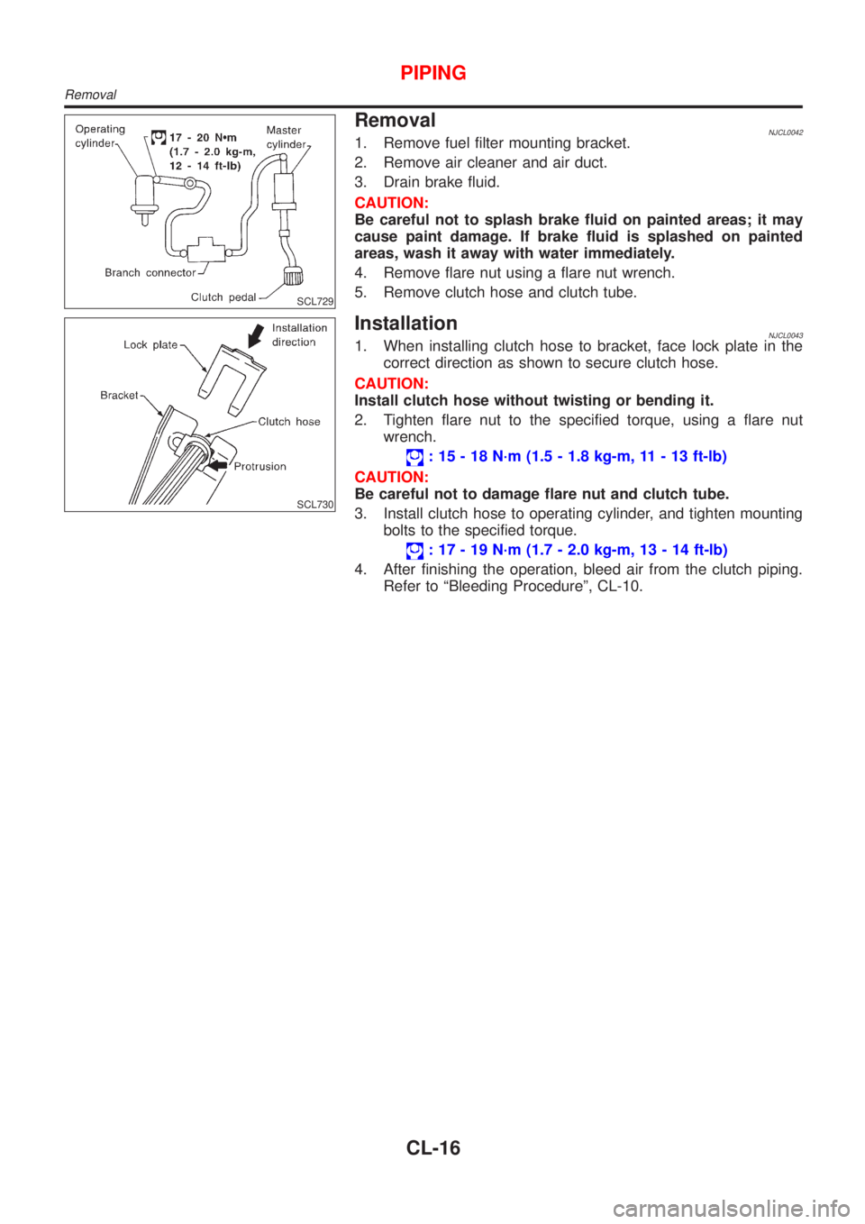
SCL729
RemovalNJCL00421. Remove fuel filter mounting bracket.
2. Remove air cleaner and air duct.
3. Drain brake fluid.
CAUTION:
Be careful not to splash brake fluid on painted areas; it may
cause paint damage. If brake fluid is splashed on painted
areas, wash it away with water immediately.
4. Remove flare nut using a flare nut wrench.
5. Remove clutch hose and clutch tube.
SCL730
InstallationNJCL00431. When installing clutch hose to bracket, face lock plate in the
correct direction as shown to secure clutch hose.
CAUTION:
Install clutch hose without twisting or bending it.
2. Tighten flare nut to the specified torque, using a flare nut
wrench.
: 15 - 18 N´m (1.5 - 1.8 kg-m, 11 - 13 ft-lb)
CAUTION:
Be careful not to damage flare nut and clutch tube.
3. Install clutch hose to operating cylinder, and tighten mounting
bolts to the specified torque.
: 17 - 19 N´m (1.7 - 2.0 kg-m, 13 - 14 ft-lb)
4. After finishing the operation, bleed air from the clutch piping.
Refer to ªBleeding Procedureº, CL-10.
PIPING
Removal
CL-16
Page 1077 of 2493
SMT940D
SMT951D
21. Pick up EGI harness clamp and install engine slinger. Next, set
chain block.
22. Jack up the air compressor engine bracket.
23. Remove engine front mounting.
24. Remove LH side mounting. Refer to EM-136, ªRemoval and
Installationº.
SMT952D
25. Jack up until engine oil filter bracket bolts are just about to
touch the side frame.
SMT941D
26. Remove bolts securing transaxle.
27. While the transaxle is suspended, withdraw the transaxle case
from the engine without hitting suspension member.
+Open the front of the transaxle when the clutch cover
appears. Then, lower the transaxle pulling it toward the
right front.
+The spacer between the engine and transaxle should be
left at the engine side.
28. Remove spacer.
REMOVAL AND INSTALLATIONRS5F50A
Removal (Cont'd)
MT-27
Page 1196 of 2493

+The fluid has an odor, is discolored, and there is no evidence of metal or clutch facing particles.
+The threads in one or more of the converter bolt holes are damaged.
+Transaxle failure did not display evidence of damaged or worn internal parts, steel particles or clutch plate
lining material in unit and inside the fluid filter.
+Vehicle has been exposed to high mileage (only). The exception may be where the torque converter clutch
dampener plate lining has seen excess wear by vehicles operated in heavy and/or constant traffic, such
as taxi, delivery or police use.
EURO-OBD SELF-DIAGNOSIS Ð EURO-OBD ÐNJAT0247S04+A/T self-diagnosis is performed by the TCM in combination with the ECM. The results can be read through
the blinking pattern of the O/D OFF indicator or the malfunction indicator (MI). Refer to the table on AT-53
for the indicator used to display each self-diagnostic result.
+The self-diagnostic results indicated by the MI are automatically stored in both the ECM and TCM memo-
ries.
Always perform the procedure ªHOW TO ERASE DTCº on AT-50 to complete the repair and avoid
unnecessary blinking of the MI.
+The following self-diagnostic items can be detected using ECM self-diagnostic results mode* only when
the O/D OFF indicator lamp does not indicate any malfunctions.
þ PNP switch
þ A/T 1st, 2nd, 3rd, or 4th gear function
*: For details of EURO-OBD, refer to EC-57, ªON BOARD DIAGNOSTIC SYSTEM DESCRIPTIONº.
+Certain systems and components, especially those related to EURO-OBD, may use a new style
slide-locking type harness connector.
For description and how to disconnect, refer to EL-5, ªHARNESS CONNECTORº.
Wiring Diagrams and Trouble DiagnosisNJAT0248When you read wiring diagrams, refer to the following:
+GI-12, ªHOW TO READ WIRING DIAGRAMSº
+EL-10, ªPOWER SUPPLY ROUTINGº
When you perform trouble diagnosis, refer to the following:
+GI-32, ªHOW TO FOLLOW TEST GROUP IN TROUBLE DIAGNOSISº
+GI-21, ªHOW TO PERFORM EFFICIENT DIAGNOSIS FOR AN ELECTRICAL INCIDENTº
PRECAUTIONS
Service Notice or Precautions (Cont'd)
AT-10
Page 1485 of 2493
6 DETECT MALFUNCTIONING ITEM
1. Remove control valve assembly. Refer to ªON-VEHICLE SERVICEº, AT-343.
2. Check the following items:
+Valves to control line pressure (Pressure regulator valve, pressure modifier valve, pilot valve and pilot filter)
+Line pressure solenoid valve (AT-174: Except for Euro-OBD/AT-237: Euro-OBD)
3. Disassemble A/T.
4. Check the following items:
+Oil pump assembly
+Torque converter
+Reverse clutch assembly
+High clutch assembly
+Low & reverse brake assembly
+Low one-way clutch
OK or NG
OK©GO TO 5.
NG©Repair or replace damaged parts.
TROUBLE DIAGNOSES FOR SYMPTOMS
6. Vehicle Does Not Creep Backward In ªRº Position (Cont'd)
AT-299
Page 1488 of 2493
6 DETECT MALFUNCTIONING ITEM
1. Remove control valve assembly. Refer to AT-343.
2. Check the following items:
+Valves to control line pressure (Pressure regulator valve, pressure modifier valve, pilot valve and pilot filter)
+Line pressure solenoid valve (AT-174: Except for Euro-OBD/AT-237: Euro-OBD)
3. Disassemble A/T.
4. Check the following items:
+Oil pump assembly
+Forward clutch assembly
+Forward one-way clutch
+Low one-way clutch
+Low & reverse brake assembly
+Torque converter
OK or NG
OK©GO TO 5.
NG©Repair or replace damaged parts.
TROUBLE DIAGNOSES FOR SYMPTOMS
7. Vehicle Does Not Creep Forward In ªDº, ª2º Or ª1º Position (Cont'd)
AT-302
Page 1491 of 2493

6 DETECT MALFUNCTIONING ITEM
1. Remove control valve assembly. Refer to AT-343.
2. Check the following items:
+Shift valve A
+Shift valve B
+Shift solenoid valve A
+Shift solenoid valve B
+Pilot valve
+Pilot filter
OK or NG
OK©GO TO 7.
NG©Repair or replace damaged parts.
7 CHECK SYMPTOM
Check again.
OK or NG
OK©INSPECTION END
NG©1. Perform TCM input/output signal inspection.
2. If NG, recheck TCM pin terminals for damage or loose connection with harness con-
nector.
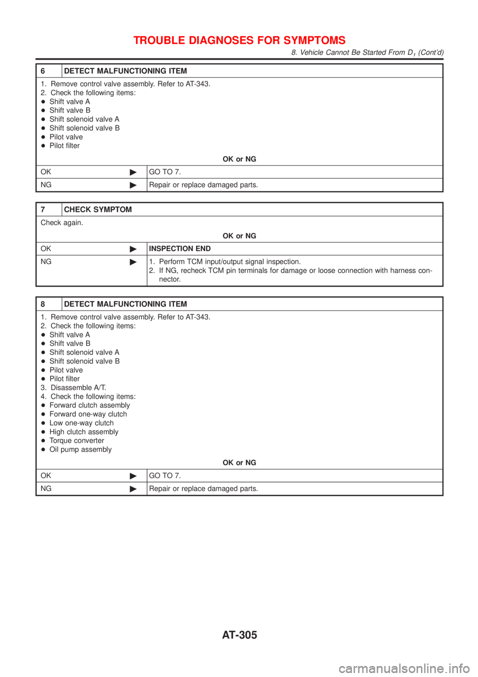
8 DETECT MALFUNCTIONING ITEM
1. Remove control valve assembly. Refer to AT-343.
2. Check the following items:
+Shift valve A
+Shift valve B
+Shift solenoid valve A
+Shift solenoid valve B
+Pilot valve
+Pilot filter
3. Disassemble A/T.
4. Check the following items:
+Forward clutch assembly
+Forward one-way clutch
+Low one-way clutch
+High clutch assembly
+Torque converter
+Oil pump assembly
OK or NG
OK©GO TO 7.
NG©Repair or replace damaged parts.
TROUBLE DIAGNOSES FOR SYMPTOMS
8. Vehicle Cannot Be Started From D1(Cont'd)
AT-305
Page 1493 of 2493
4 CHECK THROTTLE POSITION SENSOR
Check throttle position sensor. Refer to EC-168, ªDTC P0120 THROTTLE POSITION SENSORº.
SAT004K
OK or NG
OK©GO TO 5.
NG©Repair or replace throttle position sensor.
5 CHECK A/T FLUID CONIDITION
1. Remove oil pan.
2. Check A/T fluid condition.
SAT171B
OK or NG
OK©GO TO 6.
NG©GO TO 8.
6 DETECT MALFUNCTIONING ITEM
1. Remove control valve. Refer to AT-343.
2. Check the following items:
+Shift valve A
+Shift solenoid valve A (AT-140: Except for Euro-OBD/AT-244: Euro-OBD)
+Pilot valve
+Pilot filter
OK or NG
OK©GO TO 7.
NG©Repair or replace damaged parts.
TROUBLE DIAGNOSES FOR SYMPTOMS
9. A/T Does Not Shift: D1®D2Or Does Not Kickdown: D4®D2(Cont'd)
AT-307
Page 1494 of 2493
7 CHECK SYMPTOM
Check again.
OK or NG
OK©INSPECTION END
NG©1. Perform TCM input/output signal inspection.
2. If NG, recheck TCM pin terminals for damage or loose connection with harness con-
nector.
8 DETECT MALFUNCTIONING ITEM
1. Remove control valve. Refer to AT-343.
2. Check the following items:
+Shift valve A
+Shift solenoid valve A (AT-140: Except for Euro-OBD/AT-244: Euro-OBD)
+Pilot valve
+Pilot filter
3. Disassemble A/T.
4. Check the following items:
+Servo piston assembly
+Brake band
+Oil pump assembly
OK or NG
OK©GO TO 7.
NG©Repair or replace damaged parts.
TROUBLE DIAGNOSES FOR SYMPTOMS
9. A/T Does Not Shift: D1®D2Or Does Not Kickdown: D4®D2(Cont'd)
AT-308