2001 NISSAN ALMERA N16 coolant
[x] Cancel search: coolantPage 219 of 2493

JEM193G
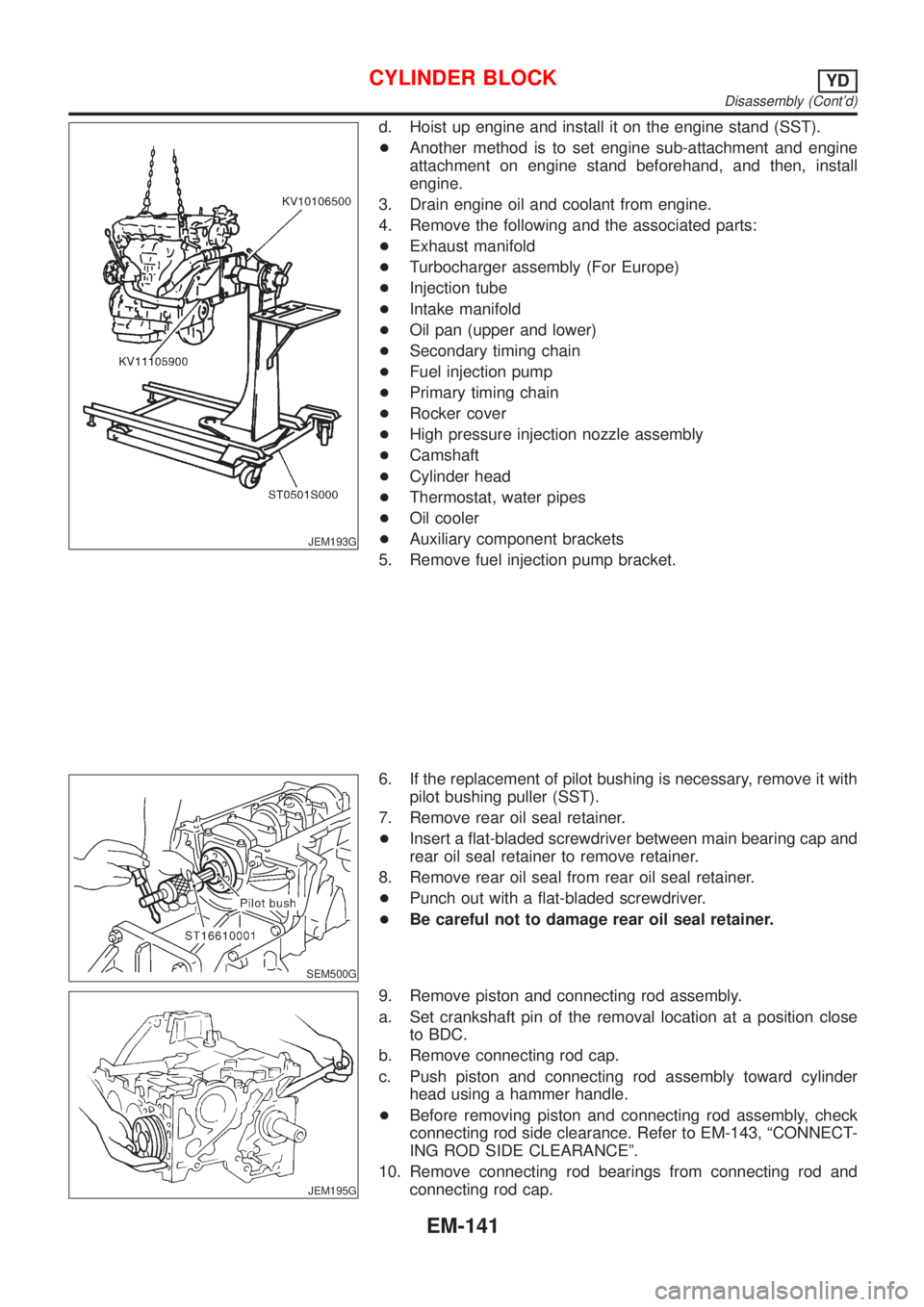
d. Hoist up engine and install it on the engine stand (SST).
+Another method is to set engine sub-attachment and engine
attachment on engine stand beforehand, and then, install
engine.
3. Drain engine oil and coolant from engine.
4. Remove the following and the associated parts:
+Exhaust manifold
+Turbocharger assembly (For Europe)
+Injection tube
+Intake manifold
+Oil pan (upper and lower)
+Secondary timing chain
+Fuel injection pump
+Primary timing chain
+Rocker cover
+High pressure injection nozzle assembly
+Camshaft
+Cylinder head
+Thermostat, water pipes
+Oil cooler
+Auxiliary component brackets
5. Remove fuel injection pump bracket.
SEM500G
6. If the replacement of pilot bushing is necessary, remove it with
pilot bushing puller (SST).
7. Remove rear oil seal retainer.
+Insert a flat-bladed screwdriver between main bearing cap and
rear oil seal retainer to remove retainer.
8. Remove rear oil seal from rear oil seal retainer.
+Punch out with a flat-bladed screwdriver.
+Be careful not to damage rear oil seal retainer.
JEM195G
9. Remove piston and connecting rod assembly.
a. Set crankshaft pin of the removal location at a position close
to BDC.
b. Remove connecting rod cap.
c. Push piston and connecting rod assembly toward cylinder
head using a hammer handle.
+Before removing piston and connecting rod assembly, check
connecting rod side clearance. Refer to EM-143, ªCONNECT-
ING ROD SIDE CLEARANCEº.
10. Remove connecting rod bearings from connecting rod and
connecting rod cap.
CYLINDER BLOCKYD
Disassembly (Cont'd)
EM-141
Page 232 of 2493

JEM222G
OIL JET RELIEF VALVENJEM0073S20Using a clean resin rod, press down on the check valve inside relief
valve. Check for appropriate bounce/repulsion and smooth
operation.
AssemblyNJEM0074PISTONNJEM0074S011. With using snap ring pliers, install snap rings to grooves at the
rear side of the piston.
+Install securely to fully fit into the groove.
2. Install piston to the connecting rod.
+Heat the piston with an industrial drier to 60 to 70ÉC (140 to
158ÉF) so that the piston pin can be easily inserted by finger.
Then, insert the piston pin from the front of the piston into the
piston and into the connecting rod.
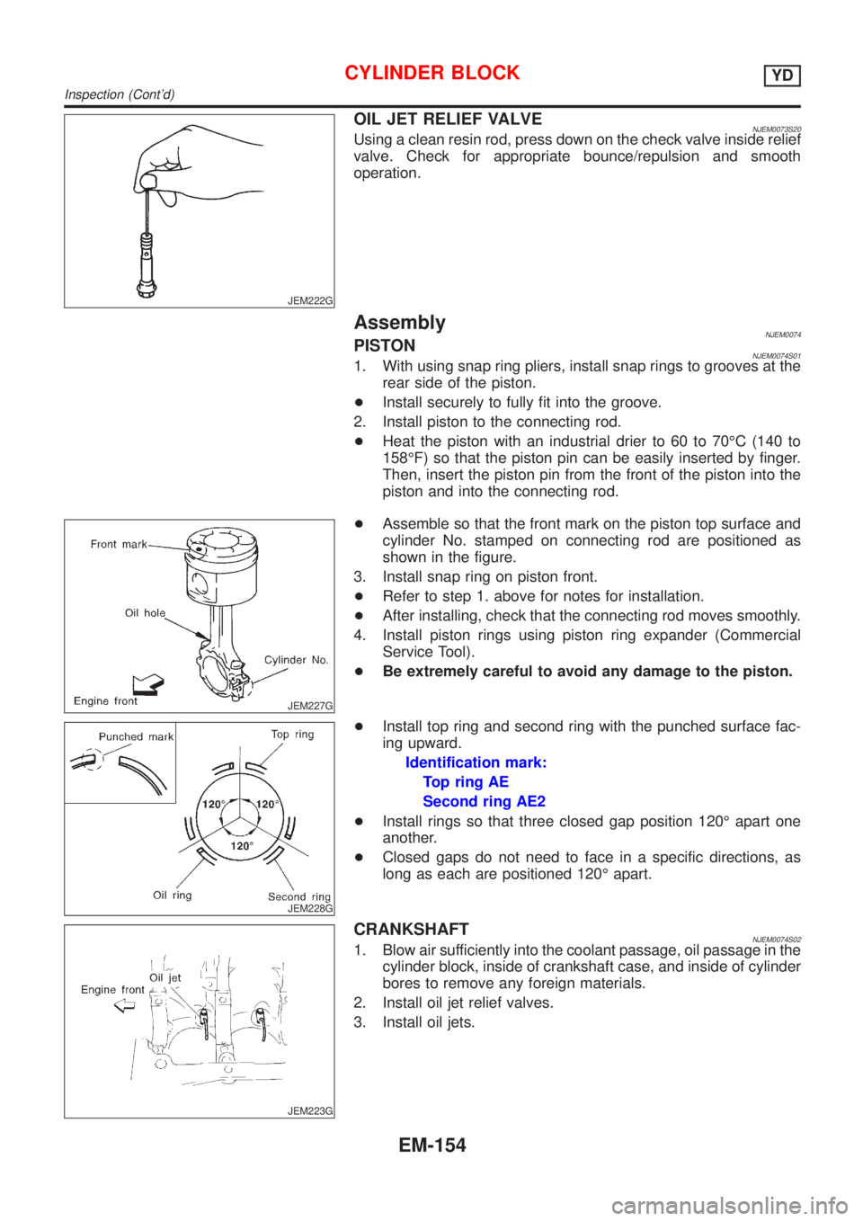
JEM227G
+Assemble so that the front mark on the piston top surface and
cylinder No. stamped on connecting rod are positioned as
shown in the figure.
3. Install snap ring on piston front.
+Refer to step 1. above for notes for installation.
+After installing, check that the connecting rod moves smoothly.
4. Install piston rings using piston ring expander (Commercial
Service Tool).
+Be extremely careful to avoid any damage to the piston.
JEM228G
+Install top ring and second ring with the punched surface fac-
ing upward.
Identification mark:
Top ring AE
Second ring AE2
+Install rings so that three closed gap position 120É apart one
another.
+Closed gaps do not need to face in a specific directions, as
long as each are positioned 120É apart.
JEM223G
CRANKSHAFTNJEM0074S021. Blow air sufficiently into the coolant passage, oil passage in the
cylinder block, inside of crankshaft case, and inside of cylinder
bores to remove any foreign materials.
2. Install oil jet relief valves.
3. Install oil jets.
CYLINDER BLOCKYD
Inspection (Cont'd)
EM-154
Page 249 of 2493

ENGINE LUBRICATION &
COOLING SYSTEMS
SECTION
LC
CONTENTS
QG
ENGINE LUBRICATION SYSTEM..................................3
Precautions ..................................................................3
LIQUID GASKET APPLICATION PROCEDURE............3
Preparation ..................................................................3
SPECIAL SERVICE TOOLS........................................3
Lubrication Circuit ........................................................4
Oil Pressure Check......................................................5
Oil Pump ......................................................................5
REMOVAL AND INSTALLATION.................................5
DISASSEMBLY AND ASSEMBLY................................6
INSPECTION.............................................................7
REGULATOR VALVE INSPECTION............................7
Changing Engine Oil....................................................8
Changing Oil Filter .......................................................9
Service Data and Specifications (SDS).....................10
OIL PRESSURE CHECK..........................................10
OIL PUMP INSPECTION..........................................10
REGULATOR VALVE INSPECTION..........................10
OIL CAPACITY........................................................10
ENGINE COOLING SYSTEM........................................ 11
Precautions ................................................................ 11
LIQUID GASKET APPLICATION PROCEDURE.......... 11
Preparation ................................................................ 11
SPECIAL SERVICE TOOLS...................................... 11
Cooling Circuit ...........................................................12
System Check............................................................12
CHECKING COOLING SYSTEM HOSES...................12
CHECKING RADIATOR............................................13
CHECKING RADIATOR CAP....................................13
CHECKING COOLING SYSTEM FOR LEAKS............13
Water Pump ...............................................................14
REMOVAL AND INSTALLATION...............................14
INSPECTION...........................................................14
Thermostat .................................................................15
REMOVAL AND INSTALLATION...............................15
INSPECTION...........................................................16
Radiator .....................................................................16
COMPONENTS.......................................................16
Cooling Fan ...............................................................17
COMPONENTS.......................................................17
CONTROL SYSTEM................................................17
Changing Engine Coolant..........................................17
- DRAINING ENGINE COOLANT -............................17
- REFILLING ENGINE COOLANT -...........................18
- FLUSHING COOLING SYSTEM -............................19
Radiator (Aluminum type) ..........................................20
PREPARATION.......................................................20
DISASSEMBLY........................................................20
ASSEMBLY.............................................................21
INSPECTION...........................................................22
Overheating Cause Analysis .....................................23
Service Data and Specifications (SDS).....................24
THERMOSTAT........................................................24
RADIATOR..............................................................24
COOLANT CAPACITY..............................................24
YD
ENGINE LUBRICATION SYSTEM................................25
Precautions ................................................................25
LIQUID GASKET APPLICATION PROCEDURE..........25
Preparation ................................................................25
SPECIAL SERVICE TOOLS......................................25
Lubrication Circuit ......................................................26
Oil Pressure Check....................................................27
Oil Pump ....................................................................27
REMOVAL AND INSTALLATION...............................27
DISASSEMBLY AND ASSEMBLY..............................28
OIL PUMP INSPECTION..........................................28
REGULATOR VALVE INSPECTION..........................29
Changing Engine Oil..................................................30
Oil Filter Bracket ........................................................31
REMOVAL AND INSTALLATION...............................31
Changing Oil Filter .....................................................31
REMOVAL...............................................................32
INSTALLATION........................................................32
Oil Cooler ...................................................................33
REMOVAL AND INSTALLATION...............................33
Service Data and Specifications (SDS).....................34
OIL PRESSURE CHECK..........................................34
Page 250 of 2493

REGULATOR VALVE INSPECTION..........................34
OIL PUMP INSPECTION..........................................34
ENGINE OIL CAPACITY...........................................34
ENGINE COOLING SYSTEM........................................35
Precautions ................................................................35
LIQUID GASKET APPLICATION PROCEDURE..........35
Preparation ................................................................35
SPECIAL SERVICE TOOLS......................................35
Cooling Circuit ...........................................................36
System Check............................................................37
CHECKING COOLING SYSTEM HOSES...................37
CHECKING RADIATOR............................................37
CHECKING RADIATOR CAP....................................37
CHECKING COOLING SYSTEM FOR LEAKS............38
Water Pump ...............................................................38
REMOVAL AND INSTALLATION...............................38
REMOVAL...............................................................39
INSPECTION...........................................................39
INSTALLATION........................................................39
Thermostat .................................................................40
REMOVAL AND INSTALLATION...............................40
INSPECTION...........................................................41
Radiator .....................................................................41
COMPONENTS.......................................................41
REMOVAL AND INSTALLATION...............................42
Cooling Fan ...............................................................42
COMPONENTS.......................................................42
CONTROL SYSTEM................................................42
Changing Engine Coolant..........................................43
- DRAINING ENGINE COOLANT -............................43
- REFILLING ENGINE COOLANT -...........................43
- FLUSHING COOLING SYSTEM -............................45
Radiator (Aluminum type) ..........................................46
Overheating Cause Analysis .....................................46
Service Data and Specifications (SDS).....................47
THERMOSTAT........................................................47
RADIATOR..............................................................47
ENGINE COOLANT CAPACITY................................47
CONTENTS(Cont'd)
LC-2
Page 251 of 2493

SEM164F
AEM080
Precautions
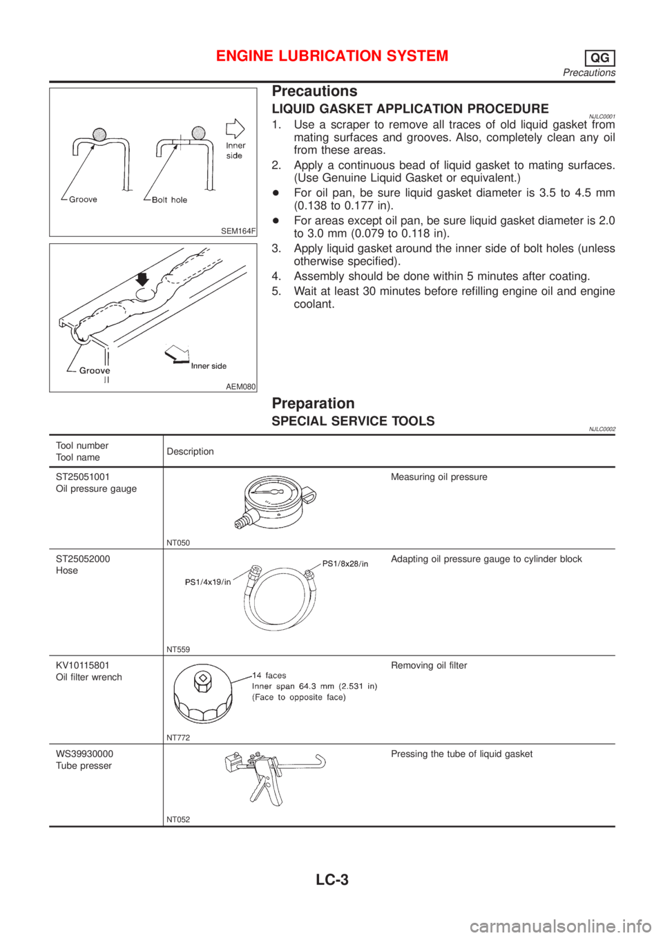
LIQUID GASKET APPLICATION PROCEDURENJLC00011. Use a scraper to remove all traces of old liquid gasket from
mating surfaces and grooves. Also, completely clean any oil
from these areas.
2. Apply a continuous bead of liquid gasket to mating surfaces.
(Use Genuine Liquid Gasket or equivalent.)
+For oil pan, be sure liquid gasket diameter is 3.5 to 4.5 mm
(0.138 to 0.177 in).
+For areas except oil pan, be sure liquid gasket diameter is 2.0
to 3.0 mm (0.079 to 0.118 in).
3. Apply liquid gasket around the inner side of bolt holes (unless
otherwise specified).
4. Assembly should be done within 5 minutes after coating.
5. Wait at least 30 minutes before refilling engine oil and engine
coolant.
Preparation
SPECIAL SERVICE TOOLSNJLC0002
Tool number
Tool nameDescription
ST25051001
Oil pressure gauge
NT050
Measuring oil pressure
ST25052000
Hose
NT559
Adapting oil pressure gauge to cylinder block
KV10115801
Oil filter wrench
NT772
Removing oil filter
WS39930000
Tube presser
NT052
Pressing the tube of liquid gasket
ENGINE LUBRICATION SYSTEMQG
Precautions
LC-3
Page 259 of 2493

SEM164F
AEM080
Precautions
LIQUID GASKET APPLICATION PROCEDURENJLC00141. Use a scraper to remove all traces of old liquid gasket from
mating surfaces and grooves. Also, completely clean any oil
from these areas.
2. Apply a continuous bead of liquid gasket to mating surfaces.
(Use Genuine Liquid Gasket or equivalent.)
+For oil pan, be sure liquid gasket diameter is 3.5 to 4.5 mm
(0.138 to 0.177 in).
+For areas except oil pan, be sure liquid gasket diameter is 2.0
to 3.0 mm (0.079 to 0.118 in).
3. Apply liquid gasket around the inner side of bolt holes (unless
otherwise specified).
4. Assembly should be done within 5 minutes after coating.
5. Wait at least 30 minutes before refilling engine oil and engine
coolant.
Preparation
SPECIAL SERVICE TOOLSNJLC0015
Tool number
Tool nameDescription
EG17650301
Radiator cap tester
adapter
NT564
Adapting radiator cap tester to radiator filler neck
a: 28 (1.10) dia.
b: 31.4 (1.236) dia.
c: 41.3 (1.626) dia.
Unit: mm (in)
KV99103510
Radiator plate pliers A
NT224
Installing radiator upper and lower tanks
KV99103520
Radiator plate pliers B
NT225
Removing radiator upper and lower tanks
ENGINE COOLING SYSTEMQG
Precautions
LC-11
Page 262 of 2493

Water Pump
REMOVAL AND INSTALLATIONNJLC0018
SEM858F
SEM859F
CAUTION:
+When removing water pump assembly, be careful not to
get coolant on drive belt.
+Water pump cannot be disassembled and should be
replaced as a unit.
+After installing water pump, and check for leaks using
radiator cap tester.
1. Drain engine coolant.
Refer to LC-17, ªChanging Engine Coolantº.
2. Remove drive belts and idler pulley.
3. Loosen water pump pulley bolts.
4. Remove water pump pulley.
5. Remove front right wheel.
6. Remove front right undercover and front right fender protector.
7. Remove water pump bolts.
8. Remove water pump.
9. Reinstall parts in reverse order of removal.
SEM860F
INSPECTIONNJLC0019+Check body assembly and vane for rust or corrosion.
+Check for rough operation due to excessive end play.
ENGINE COOLING SYSTEMQG
Water Pump
LC-14
Page 263 of 2493

Thermostat
REMOVAL AND INSTALLATIONNJLC0021
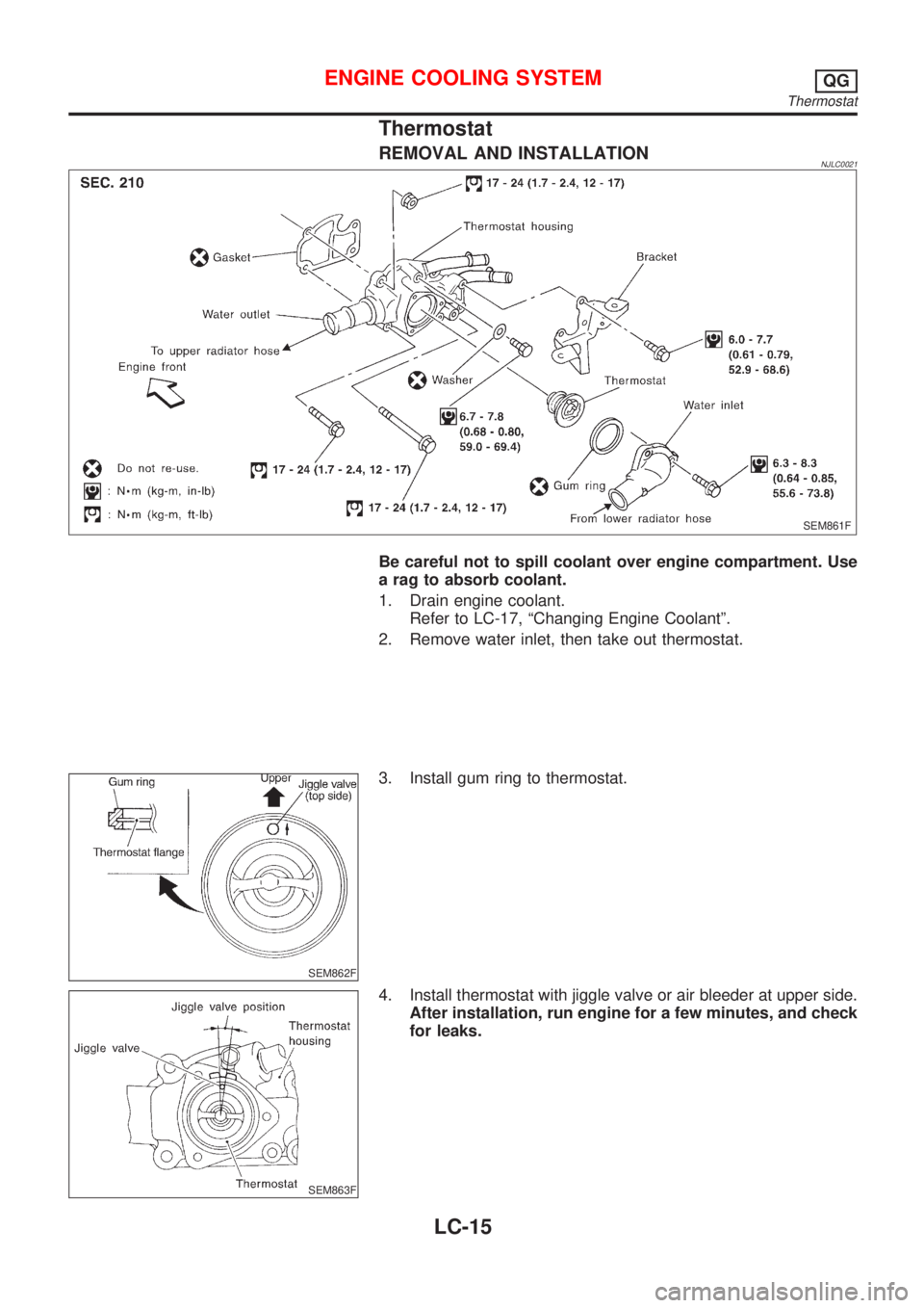
SEM861F
Be careful not to spill coolant over engine compartment. Use
a rag to absorb coolant.
1. Drain engine coolant.
Refer to LC-17, ªChanging Engine Coolantº.
2. Remove water inlet, then take out thermostat.
SEM862F
3. Install gum ring to thermostat.
SEM863F
4. Install thermostat with jiggle valve or air bleeder at upper side.
After installation, run engine for a few minutes, and check
for leaks.
ENGINE COOLING SYSTEMQG
Thermostat
LC-15