2001 NISSAN ALMERA N16 change time
[x] Cancel search: change timePage 511 of 2493
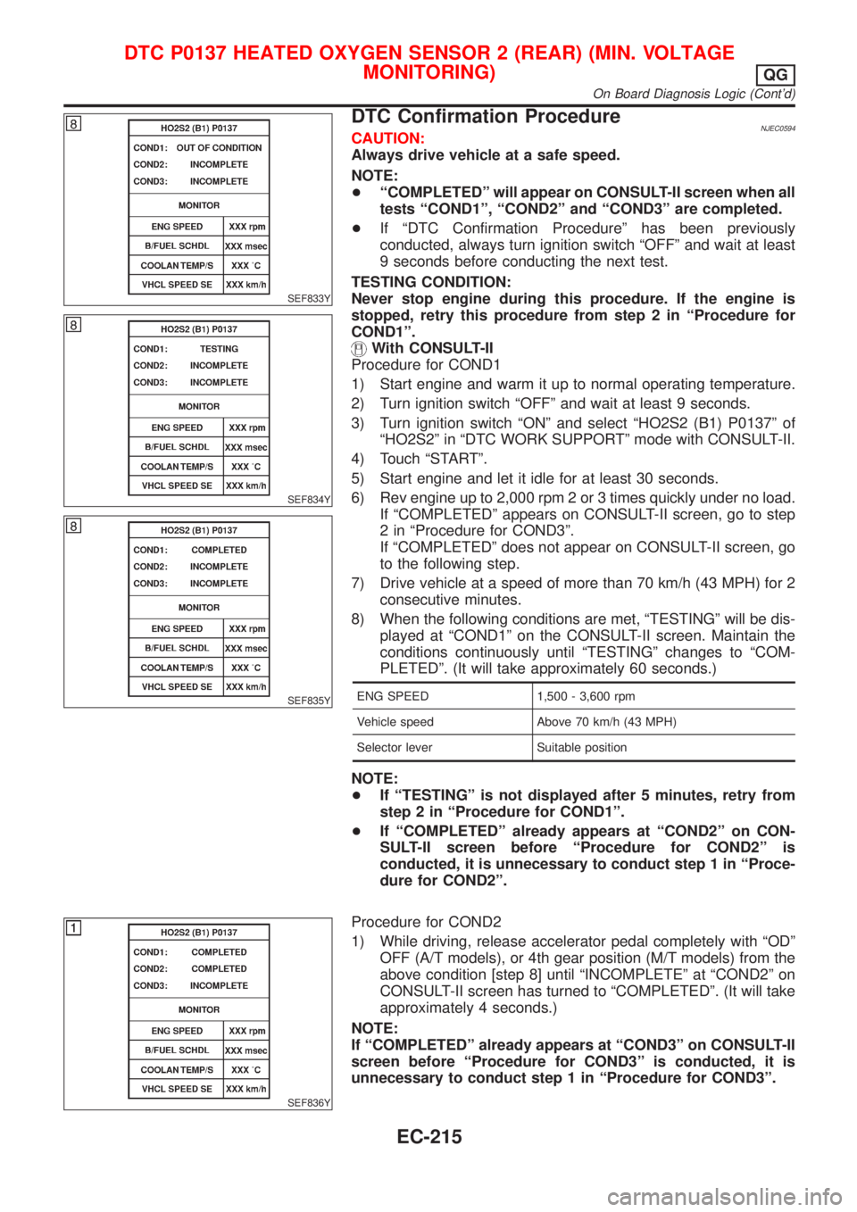
SEF833Y
SEF834Y
SEF835Y
DTC Confirmation ProcedureNJEC0594CAUTION:
Always drive vehicle at a safe speed.
NOTE:
+ªCOMPLETEDº will appear on CONSULT-II screen when all
tests ªCOND1º, ªCOND2º and ªCOND3º are completed.
+If ªDTC Confirmation Procedureº has been previously
conducted, always turn ignition switch ªOFFº and wait at least
9 seconds before conducting the next test.
TESTING CONDITION:
Never stop engine during this procedure. If the engine is
stopped, retry this procedure from step 2 in ªProcedure for
COND1º.
With CONSULT-II
Procedure for COND1
1) Start engine and warm it up to normal operating temperature.
2) Turn ignition switch ªOFFº and wait at least 9 seconds.
3) Turn ignition switch ªONº and select ªHO2S2 (B1) P0137º of
ªHO2S2º in ªDTC WORK SUPPORTº mode with CONSULT-II.
4) Touch ªSTARTº.
5) Start engine and let it idle for at least 30 seconds.
6) Rev engine up to 2,000 rpm 2 or 3 times quickly under no load.
If ªCOMPLETEDº appears on CONSULT-II screen, go to step
2 in ªProcedure for COND3º.
If ªCOMPLETEDº does not appear on CONSULT-II screen, go
to the following step.
7) Drive vehicle at a speed of more than 70 km/h (43 MPH) for 2
consecutive minutes.
8) When the following conditions are met, ªTESTINGº will be dis-
played at ªCOND1º on the CONSULT-II screen. Maintain the
conditions continuously until ªTESTINGº changes to ªCOM-
PLETEDº. (It will take approximately 60 seconds.)
ENG SPEED 1,500 - 3,600 rpm
Vehicle speed Above 70 km/h (43 MPH)
Selector lever Suitable position
NOTE:
+If ªTESTINGº is not displayed after 5 minutes, retry from
step 2 in ªProcedure for COND1º.
+If ªCOMPLETEDº already appears at ªCOND2º on CON-
SULT-II screen before ªProcedure for COND2º is
conducted, it is unnecessary to conduct step 1 in ªProce-
dure for COND2º.
SEF836Y
Procedure for COND2
1) While driving, release accelerator pedal completely with ªODº
OFF (A/T models), or 4th gear position (M/T models) from the
above condition [step 8] until ªINCOMPLETEº at ªCOND2º on
CONSULT-II screen has turned to ªCOMPLETEDº. (It will take
approximately 4 seconds.)
NOTE:
If ªCOMPLETEDº already appears at ªCOND3º on CONSULT-II
screen before ªProcedure for COND3º is conducted, it is
unnecessary to conduct step 1 in ªProcedure for COND3º.
DTC P0137 HEATED OXYGEN SENSOR 2 (REAR) (MIN. VOLTAGE
MONITORING)
QG
On Board Diagnosis Logic (Cont'd)
EC-215
Page 519 of 2493

SEF837Y
SEF838Y
SEF839Y
DTC Confirmation ProcedureNJEC0596CAUTION:
Always drive vehicle at a safe speed.
NOTE:
+ªCOMPLETEDº will appear on CONSULT-II screen when all
tests ªCOND1º, ªCOND2º and ªCOND3º are completed.
+If ªDTC Confirmation Procedureº has been previously
conducted, always turn ignition switch ªOFFº and wait at least
9 seconds before conducting the next test.
TESTING CONDITION:
Never stop engine during this procedure. If the engine is
stopped, retry this procedure from step 2 in ªProcedure for
COND1º.
With CONSULT-II
Procedure for COND1
1) Start engine and warm it up to normal operating temperature.
2) Turn ignition switch ªOFFº and wait at least 9 seconds.
3) Turn ignition switch ªONº and select ªHO2S2 (B1) P0138º of
ªHO2S2º in ªDTC WORK SUPPORTº mode with CONSULT-II.
4) Touch ªSTARTº.
5) Start engine and let it idle for at least 30 seconds.
6) Rev engine up to 2,000 rpm 2 or 3 times quickly under no load.
If ªCOMPLETEDº appears on CONSULT-II screen, go to step
2 in ªProcedure for COND3º.
If ªCOMPLETEDº does not appear on CONSULT-II screen, go
to the following step.
7) Drive vehicle at a speed of more than 70 km/h (43 MPH) for 2
consecutive minutes.
8) When the following conditions are met, ªTESTINGº will be dis-
played at ªCOND1º on the CONSULT-II screen. Maintain the
conditions continuously until ªTESTINGº changes to ªCOM-
PLETEDº. (It will take approximately 60 seconds.)
ENG SPEED 1,500 - 3,600 rpm
Vehicle speed Above 70 km/h (43 MPH)
Selector lever Suitable position
NOTE:
+If ªTESTINGº is not displayed after 5 minutes, retry from
step 2 in ªProcedure for COND1º.
+If ªCOMPLETEDº already appears at ªCOND2º on CON-
SULT-II screen before ªProcedure for COND2º is
conducted, it is unnecessary to conduct step 1 in ªProce-
dure for COND2º.
SEF840Y
Procedure for COND2
1) While driving, release accelerator pedal completely with ªODº
OFF (A/T models), or 4th gear position (M/T models) from the
above condition [step 8] until ªINCOMPLETEº at ªCOND2º on
CONSULT-II screen is turned to ªCOMPLETEDº. (It will take
approximately 4 seconds.)
NOTE:
If ªCOMPLETEDº already appears at ªCOND3º on CONSULT-II
screen before ªProcedure for COND3º is conducted, it is
unnecessary to conduct step 1 in ªProcedure for COND3º.
DTC P0138 HEATED OXYGEN SENSOR 2 (REAR) (MAX. VOLTAGE
MONITORING)
QG
On Board Diagnosis Logic (Cont'd)
EC-223
Page 526 of 2493
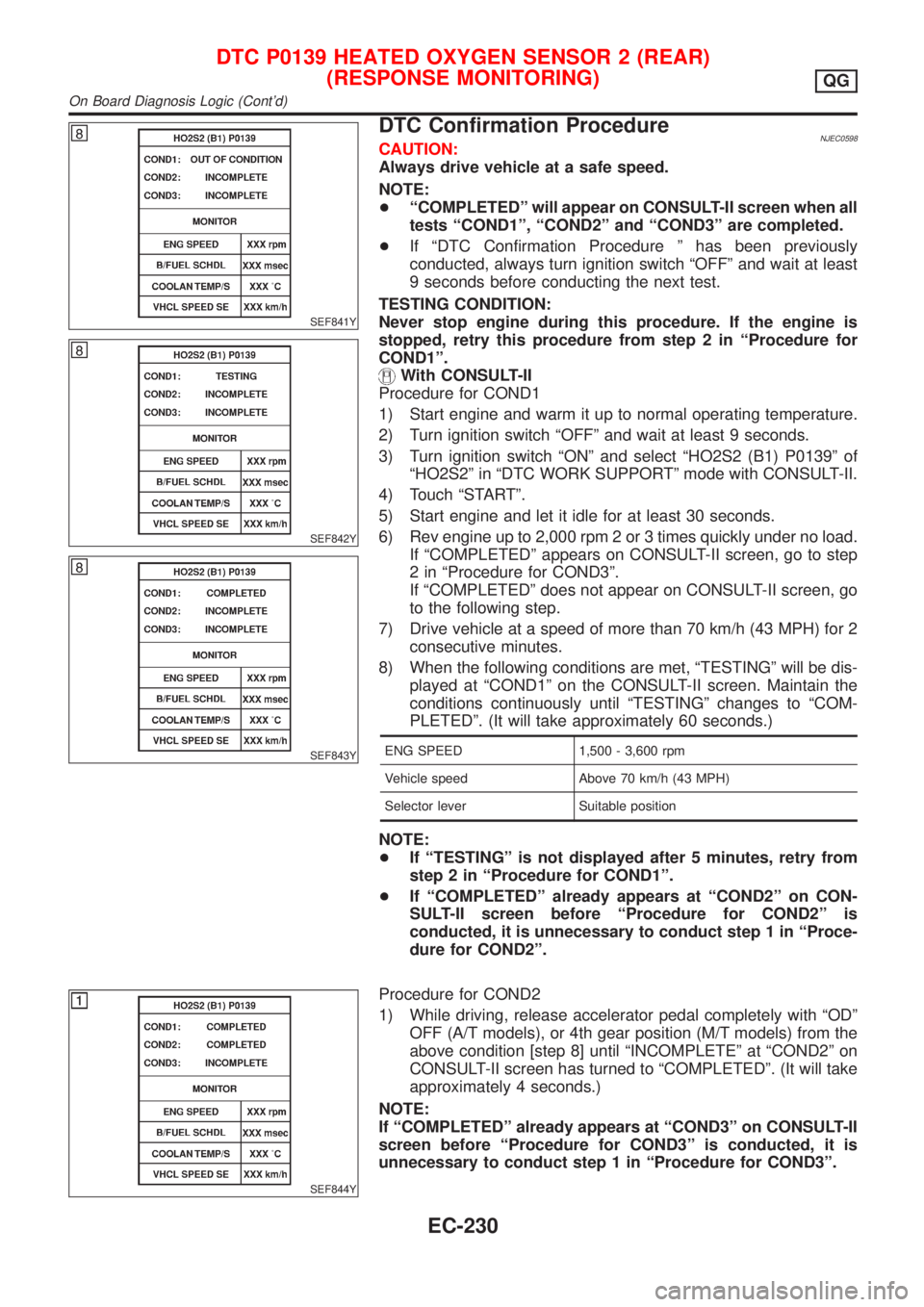
SEF841Y
SEF842Y
SEF843Y
DTC Confirmation ProcedureNJEC0598CAUTION:
Always drive vehicle at a safe speed.
NOTE:
+ªCOMPLETEDº will appear on CONSULT-II screen when all
tests ªCOND1º, ªCOND2º and ªCOND3º are completed.
+If ªDTC Confirmation Procedure º has been previously
conducted, always turn ignition switch ªOFFº and wait at least
9 seconds before conducting the next test.
TESTING CONDITION:
Never stop engine during this procedure. If the engine is
stopped, retry this procedure from step 2 in ªProcedure for
COND1º.
With CONSULT-II
Procedure for COND1
1) Start engine and warm it up to normal operating temperature.
2) Turn ignition switch ªOFFº and wait at least 9 seconds.
3) Turn ignition switch ªONº and select ªHO2S2 (B1) P0139º of
ªHO2S2º in ªDTC WORK SUPPORTº mode with CONSULT-II.
4) Touch ªSTARTº.
5) Start engine and let it idle for at least 30 seconds.
6) Rev engine up to 2,000 rpm 2 or 3 times quickly under no load.
If ªCOMPLETEDº appears on CONSULT-II screen, go to step
2 in ªProcedure for COND3º.
If ªCOMPLETEDº does not appear on CONSULT-II screen, go
to the following step.
7) Drive vehicle at a speed of more than 70 km/h (43 MPH) for 2
consecutive minutes.
8) When the following conditions are met, ªTESTINGº will be dis-
played at ªCOND1º on the CONSULT-II screen. Maintain the
conditions continuously until ªTESTINGº changes to ªCOM-
PLETEDº. (It will take approximately 60 seconds.)
ENG SPEED 1,500 - 3,600 rpm
Vehicle speed Above 70 km/h (43 MPH)
Selector lever Suitable position
NOTE:
+If ªTESTINGº is not displayed after 5 minutes, retry from
step 2 in ªProcedure for COND1º.
+If ªCOMPLETEDº already appears at ªCOND2º on CON-
SULT-II screen before ªProcedure for COND2º is
conducted, it is unnecessary to conduct step 1 in ªProce-
dure for COND2º.
SEF844Y
Procedure for COND2
1) While driving, release accelerator pedal completely with ªODº
OFF (A/T models), or 4th gear position (M/T models) from the
above condition [step 8] until ªINCOMPLETEº at ªCOND2º on
CONSULT-II screen has turned to ªCOMPLETEDº. (It will take
approximately 4 seconds.)
NOTE:
If ªCOMPLETEDº already appears at ªCOND3º on CONSULT-II
screen before ªProcedure for COND3º is conducted, it is
unnecessary to conduct step 1 in ªProcedure for COND3º.
DTC P0139 HEATED OXYGEN SENSOR 2 (REAR)
(RESPONSE MONITORING)
QG
On Board Diagnosis Logic (Cont'd)
EC-230
Page 527 of 2493
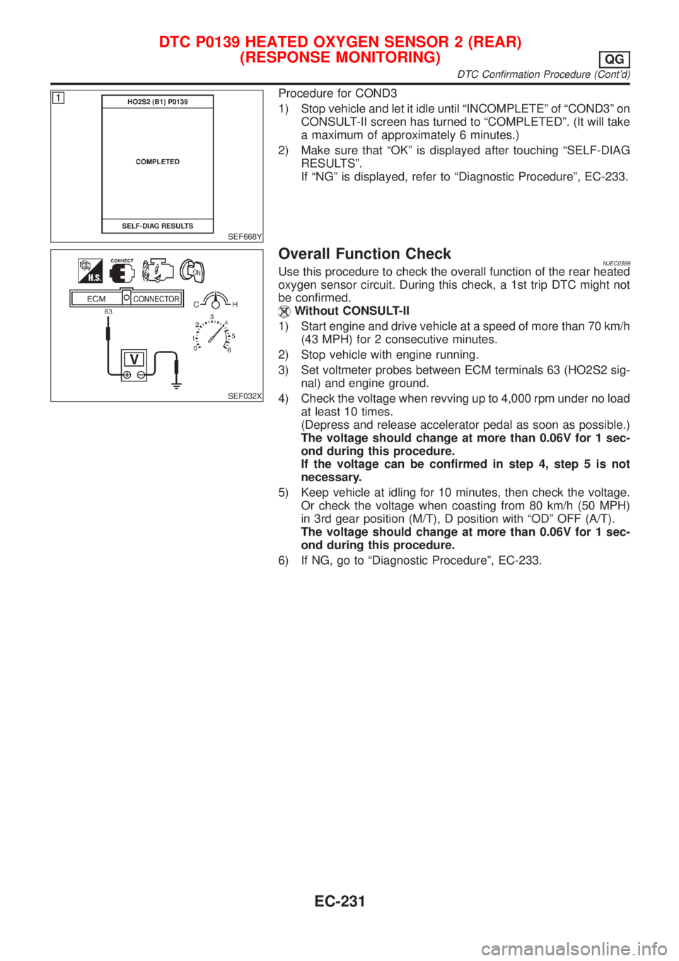
SEF668Y
Procedure for COND3
1) Stop vehicle and let it idle until ªINCOMPLETEº of ªCOND3º on
CONSULT-II screen has turned to ªCOMPLETEDº. (It will take
a maximum of approximately 6 minutes.)
2) Make sure that ªOKº is displayed after touching ªSELF-DIAG
RESULTSº.
If ªNGº is displayed, refer to ªDiagnostic Procedureº, EC-233.
SEF032X
Overall Function CheckNJEC0599Use this procedure to check the overall function of the rear heated
oxygen sensor circuit. During this check, a 1st trip DTC might not
be confirmed.
Without CONSULT-II
1) Start engine and drive vehicle at a speed of more than 70 km/h
(43 MPH) for 2 consecutive minutes.
2) Stop vehicle with engine running.
3) Set voltmeter probes between ECM terminals 63 (HO2S2 sig-
nal) and engine ground.
4) Check the voltage when revving up to 4,000 rpm under no load
at least 10 times.
(Depress and release accelerator pedal as soon as possible.)
The voltage should change at more than 0.06V for 1 sec-
ond during this procedure.
If the voltage can be confirmed in step 4, step 5 is not
necessary.
5) Keep vehicle at idling for 10 minutes, then check the voltage.
Or check the voltage when coasting from 80 km/h (50 MPH)
in 3rd gear position (M/T), D position with ªODº OFF (A/T).
The voltage should change at more than 0.06V for 1 sec-
ond during this procedure.
6) If NG, go to ªDiagnostic Procedureº, EC-233.
DTC P0139 HEATED OXYGEN SENSOR 2 (REAR)
(RESPONSE MONITORING)
QG
DTC Confirmation Procedure (Cont'd)
EC-231
Page 582 of 2493
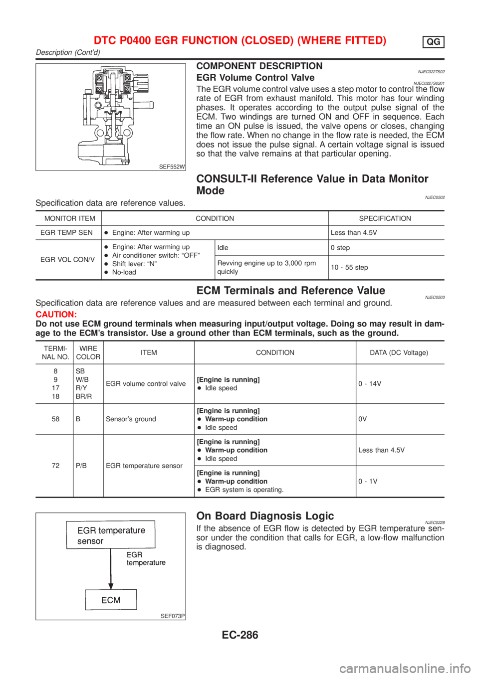
SEF552W
COMPONENT DESCRIPTIONNJEC0227S02EGR Volume Control ValveNJEC0227S0201The EGR volume control valve uses a step motor to control the flow
rate of EGR from exhaust manifold. This motor has four winding
phases. It operates according to the output pulse signal of the
ECM. Two windings are turned ON and OFF in sequence. Each
time an ON pulse is issued, the valve opens or closes, changing
the flow rate. When no change in the flow rate is needed, the ECM
does not issue the pulse signal. A certain voltage signal is issued
so that the valve remains at that particular opening.
CONSULT-II Reference Value in Data Monitor
Mode
NJEC0502Specification data are reference values.
MONITOR ITEM CONDITION SPECIFICATION
EGR TEMP SEN+Engine: After warming up Less than 4.5V
EGR VOL CON/V+Engine: After warming up
+Air conditioner switch: ªOFFº
+Shift lever: ªNº
+No-loadIdle 0 step
Revving engine up to 3,000 rpm
quickly10 - 55 step
ECM Terminals and Reference ValueNJEC0503Specification data are reference values and are measured between each terminal and ground.
CAUTION:
Do not use ECM ground terminals when measuring input/output voltage. Doing so may result in dam-
age to the ECM's transistor. Use a ground other than ECM terminals, such as the ground.
TERMI-
NAL NO.WIRE
COLORITEM CONDITION DATA (DC Voltage)
8
9
17
18SB
W/B
R/Y
BR/REGR volume control valve[Engine is running]
+Idle speed0 - 14V
58 B Sensor's ground[Engine is running]
+Warm-up condition
+Idle speed0V
72 P/B EGR temperature sensor[Engine is running]
+Warm-up condition
+Idle speedLess than 4.5V
[Engine is running]
+Warm-up condition
+EGR system is operating.0-1V
SEF073P
On Board Diagnosis LogicNJEC0228If the absence of EGR flow is detected by EGR temperature sen-
sor under the condition that calls for EGR, a low-flow malfunction
is diagnosed.
DTC P0400 EGR FUNCTION (CLOSED) (WHERE FITTED)QG
Description (Cont'd)
EC-286
Page 590 of 2493
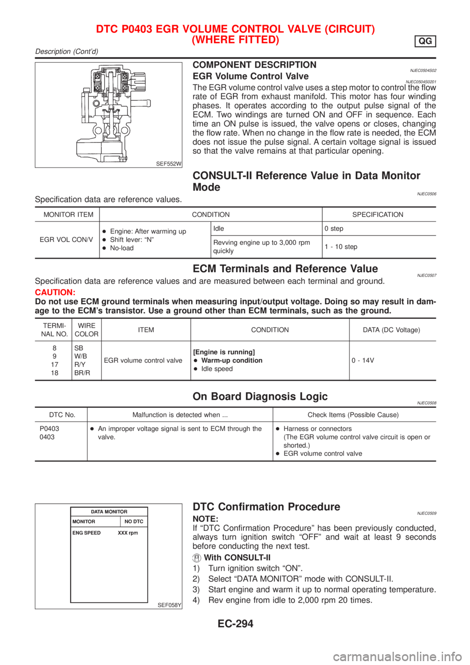
SEF552W
COMPONENT DESCRIPTIONNJEC0504S02EGR Volume Control ValveNJEC0504S0201The EGR volume control valve uses a step motor to control the flow
rate of EGR from exhaust manifold. This motor has four winding
phases. It operates according to the output pulse signal of the
ECM. Two windings are turned ON and OFF in sequence. Each
time an ON pulse is issued, the valve opens or closes, changing
the flow rate. When no change in the flow rate is needed, the ECM
does not issue the pulse signal. A certain voltage signal is issued
so that the valve remains at that particular opening.
CONSULT-II Reference Value in Data Monitor
Mode
NJEC0506Specification data are reference values.
MONITOR ITEM CONDITION SPECIFICATION
EGR VOL CON/V+Engine: After warming up
+Shift lever: ªNº
+No-loadIdle 0 step
Revving engine up to 3,000 rpm
quickly1 - 10 step
ECM Terminals and Reference ValueNJEC0507Specification data are reference values and are measured between each terminal and ground.
CAUTION:
Do not use ECM ground terminals when measuring input/output voltage. Doing so may result in dam-
age to the ECM's transistor. Use a ground other than ECM terminals, such as the ground.
TERMI-
NAL NO.WIRE
COLORITEM CONDITION DATA (DC Voltage)
8
9
17
18SB
W/B
R/Y
BR/REGR volume control valve[Engine is running]
+Warm-up condition
+Idle speed0 - 14V
On Board Diagnosis LogicNJEC0508
DTC No. Malfunction is detected when ... Check Items (Possible Cause)
P0403
0403+An improper voltage signal is sent to ECM through the
valve.+Harness or connectors
(The EGR volume control valve circuit is open or
shorted.)
+EGR volume control valve
SEF058Y
DTC Confirmation ProcedureNJEC0509NOTE:
If ªDTC Confirmation Procedureº has been previously conducted,
always turn ignition switch ªOFFº and wait at least 9 seconds
before conducting the next test.
With CONSULT-II
1) Turn ignition switch ªONº.
2) Select ªDATA MONITORº mode with CONSULT-II.
3) Start engine and warm it up to normal operating temperature.
4) Rev engine from idle to 2,000 rpm 20 times.
DTC P0403 EGR VOLUME CONTROL VALVE (CIRCUIT)
(WHERE FITTED)
QG
Description (Cont'd)
EC-294
Page 609 of 2493
DescriptionNJEC0279SYSTEM DESCRIPTIONNJEC0279S01
Sensor Input Signal to ECMECM func-
tionActuator
Crankshaft position sensor (POS) Engine speed
Idle air
controlIACV-AAC valve Camshaft position sensor (PHASE) Engine speed and cylinder number
Engine coolant temperature sensor Engine coolant temperature
Ignition switch Start signal
Throttle position sensor Throttle position
PNP switch Park/Neutral position
Air conditioner switch Air conditioner operation
Power steering oil pressure switch Power steering load signal
Battery Battery voltage
Vehicle speed sensor Vehicle speed
Cooling fan Cooling fan operation
Electrical load Electrical load signal
This system automatically controls engine idle speed to a specified
level. Idle speed is controlled through fine adjustment of the
amount of air which by-passes the throttle valve via IACV-AAC
valve. The IACV-AAC valve changes the opening of the air by-pass
passage to control the amount of auxiliary air. This valve is actu-
ated by a step motor built into the valve, which moves the valve in
the axial direction in steps corresponding to the ECM output sig-
nals. One step of IACV-AAC valve movement causes the respec-
tive opening of the air by-pass passage. (i.e. when the step
advances, the opening is enlarged.) The opening of the valve is
varied to allow for optimum control of the engine idling speed. The
crankshaft position sensor (POS) detects the actual engine speed
and sends a signal to the ECM. The ECM then controls the step
position of the IACV-AAC valve so that engine speed coincides with
the target value memorized in ECM. The target engine speed is the
lowest speed at which the engine can operate steadily. The opti-
mum value stored in the ECM is determined by taking into consid-
eration various engine conditions, such as during warm up,
deceleration, and engine load (air conditioner, power steering, cool-
ing fan operation and electrical load).
SEF937W
COMPONENT DESCRIPTIONNJEC0279S02IACV-AAC ValveNJEC0279S0202The IACV-AAC valve is operated by a step motor for centralized
control of auxiliary air supply. This motor has four winding phases
and is actuated by the output signals of ECM which turns ON and
OFF two windings each in sequence. Each time the IACV-AAC
valve opens or closes to change the auxiliary air quantity, the ECM
sends a pulse signal to the step motor. When no change in the
auxiliary air quantity is needed, the ECM does not issue the pulse
signal. A certain voltage signal is issued so that the valve remains
at that particular opening.
DTC P0505 IDLE AIR CONTROL VALVE (IACV) Ð AUXILIARY AIR CONTROL
(AAC) VALVE
QG
Description
EC-313
Page 650 of 2493
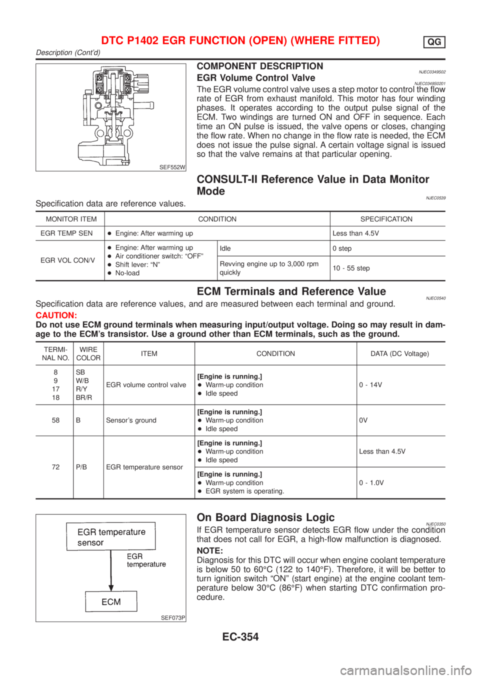
SEF552W
COMPONENT DESCRIPTIONNJEC0349S02EGR Volume Control ValveNJEC0349S0201The EGR volume control valve uses a step motor to control the flow
rate of EGR from exhaust manifold. This motor has four winding
phases. It operates according to the output pulse signal of the
ECM. Two windings are turned ON and OFF in sequence. Each
time an ON pulse is issued, the valve opens or closes, changing
the flow rate. When no change in the flow rate is needed, the ECM
does not issue the pulse signal. A certain voltage signal is issued
so that the valve remains at that particular opening.
CONSULT-II Reference Value in Data Monitor
Mode
NJEC0539Specification data are reference values.
MONITOR ITEM CONDITION SPECIFICATION
EGR TEMP SEN+Engine: After warming up Less than 4.5V
EGR VOL CON/V+Engine: After warming up
+Air conditioner switch: ªOFFº
+Shift lever: ªNº
+No-loadIdle 0 step
Revving engine up to 3,000 rpm
quickly10 - 55 step
ECM Terminals and Reference ValueNJEC0540Specification data are reference values, and are measured between each terminal and ground.
CAUTION:
Do not use ECM ground terminals when measuring input/output voltage. Doing so may result in dam-
age to the ECM's transistor. Use a ground other than ECM terminals, such as the ground.
TERMI-
NAL NO.WIRE
COLORITEM CONDITION DATA (DC Voltage)
8
9
17
18SB
W/B
R/Y
BR/REGR volume control valve[Engine is running.]
+Warm-up condition
+Idle speed0 - 14V
58 B Sensor's ground[Engine is running.]
+Warm-up condition
+Idle speed0V
72 P/B EGR temperature sensor[Engine is running.]
+Warm-up condition
+Idle speedLess than 4.5V
[Engine is running.]
+Warm-up condition
+EGR system is operating.0 - 1.0V
SEF073P
On Board Diagnosis LogicNJEC0350If EGR temperature sensor detects EGR flow under the condition
that does not call for EGR, a high-flow malfunction is diagnosed.
NOTE:
Diagnosis for this DTC will occur when engine coolant temperature
is below 50 to 60ÉC (122 to 140ÉF). Therefore, it will be better to
turn ignition switch ªONº (start engine) at the engine coolant tem-
perature below 30ÉC (86ÉF) when starting DTC confirmation pro-
cedure.
DTC P1402 EGR FUNCTION (OPEN) (WHERE FITTED)QG
Description (Cont'd)
EC-354