2001 NISSAN ALMERA N16 change time
[x] Cancel search: change timePage 669 of 2493
SEF463R
SEF288D
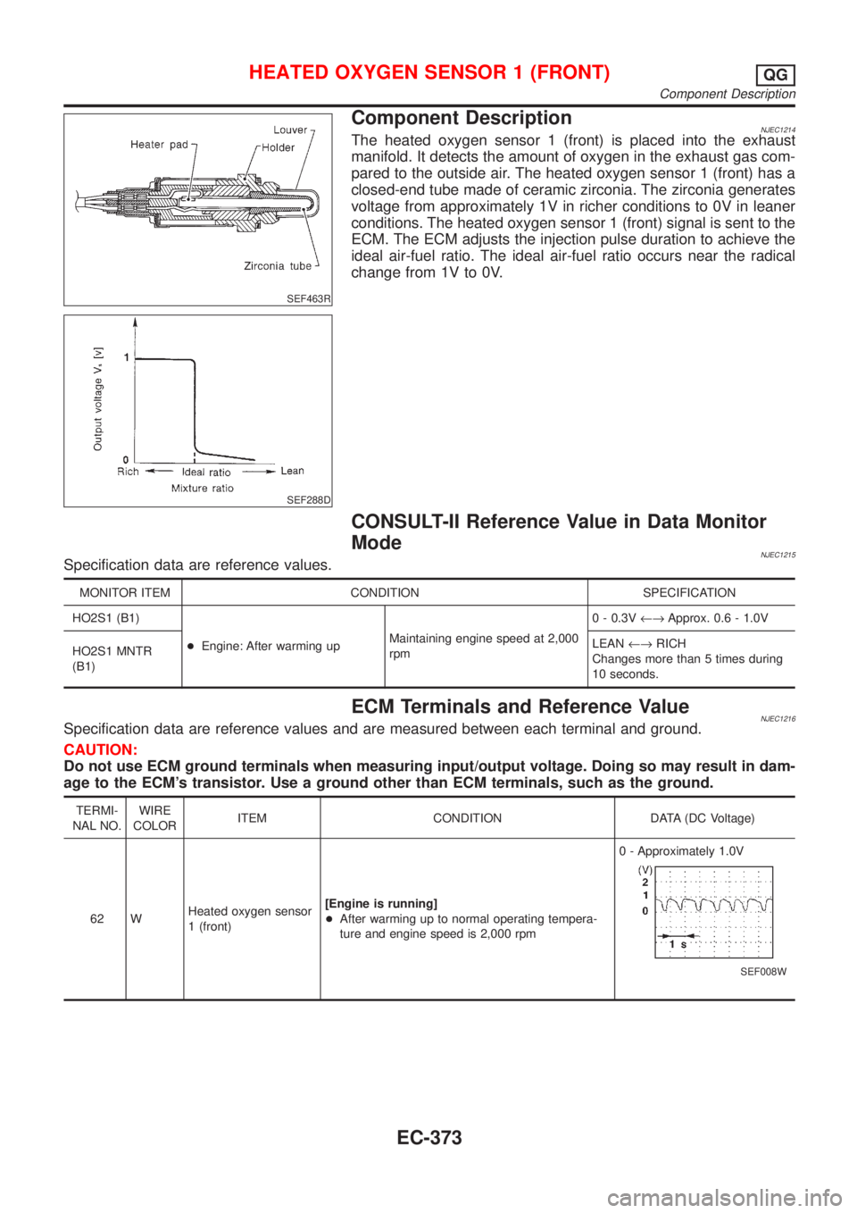
Component DescriptionNJEC1214The heated oxygen sensor 1 (front) is placed into the exhaust
manifold. It detects the amount of oxygen in the exhaust gas com-
pared to the outside air. The heated oxygen sensor 1 (front) has a
closed-end tube made of ceramic zirconia. The zirconia generates
voltage from approximately 1V in richer conditions to 0V in leaner
conditions. The heated oxygen sensor 1 (front) signal is sent to the
ECM. The ECM adjusts the injection pulse duration to achieve the
ideal air-fuel ratio. The ideal air-fuel ratio occurs near the radical
change from 1V to 0V.
CONSULT-II Reference Value in Data Monitor
Mode
NJEC1215Specification data are reference values.
MONITOR ITEM CONDITION SPECIFICATION
HO2S1 (B1)
+Engine: After warming upMaintaining engine speed at 2,000
rpm0 - 0.3V¨Approx. 0.6 - 1.0V
HO2S1 MNTR
(B1)LEAN¨RICH
Changes more than 5 times during
10 seconds.
ECM Terminals and Reference ValueNJEC1216Specification data are reference values and are measured between each terminal and ground.
CAUTION:
Do not use ECM ground terminals when measuring input/output voltage. Doing so may result in dam-
age to the ECM's transistor. Use a ground other than ECM terminals, such as the ground.
TERMI-
NAL NO.WIRE
COLORITEM CONDITION DATA (DC Voltage)
62 WHeated oxygen sensor
1 (front)[Engine is running]
+After warming up to normal operating tempera-
ture and engine speed is 2,000 rpm0 - Approximately 1.0V
SEF008W
HEATED OXYGEN SENSOR 1 (FRONT)QG
Component Description
EC-373
Page 673 of 2493
7 CHECK HEATED OXYGEN SENSOR 1 (FRONT)
Refer to ªComponent Inspectionº, EC-377.
OK or NG
OK©GO TO 8.
NG©Replace heated oxygen sensor 1 (front).
8 CHECK INTERMITTENT INCIDENT
Perform ªTROUBLE DIAGNOSIS FOR INTERMITTENT INCIDENTº, EC-144.
©INSPECTION END
SEF646Y
SEF647Y
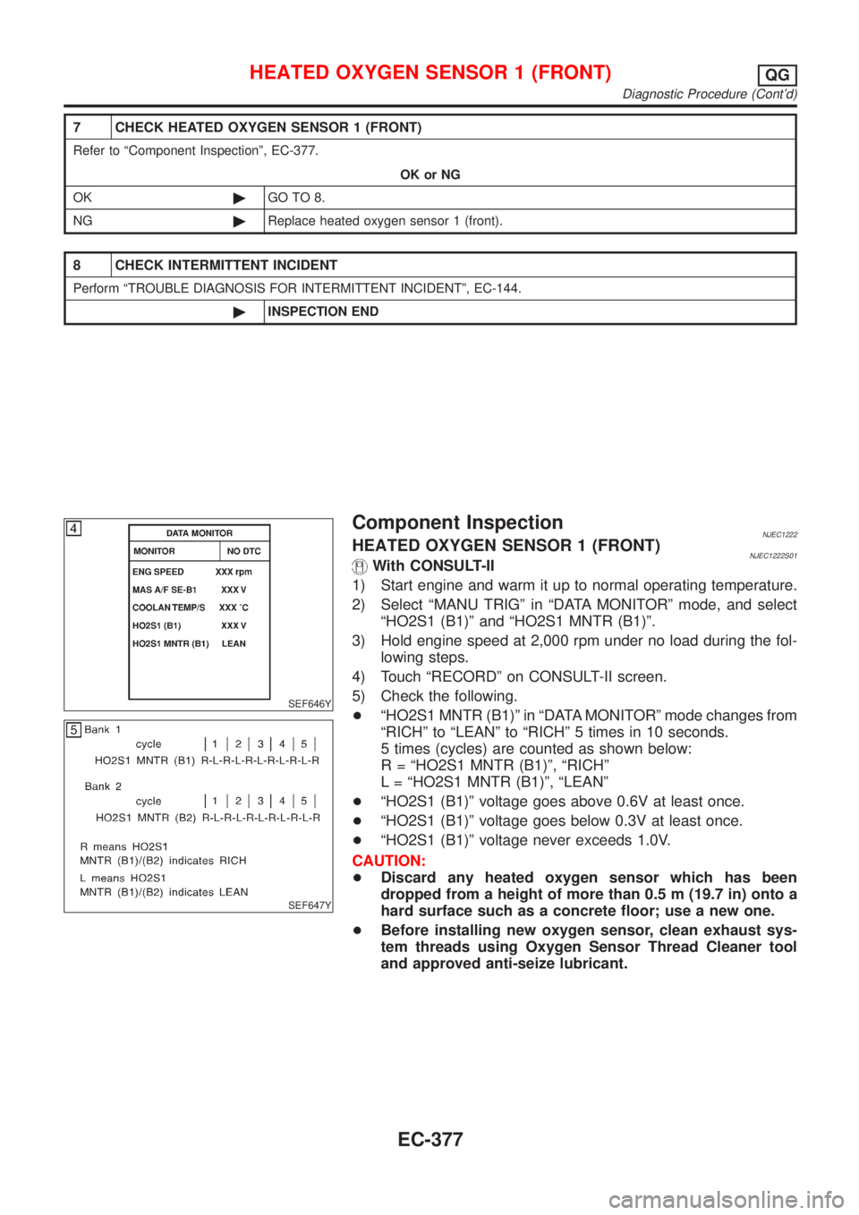
Component InspectionNJEC1222HEATED OXYGEN SENSOR 1 (FRONT)NJEC1222S01With CONSULT-II
1) Start engine and warm it up to normal operating temperature.
2) Select ªMANU TRIGº in ªDATA MONITORº mode, and select
ªHO2S1 (B1)º and ªHO2S1 MNTR (B1)º.
3) Hold engine speed at 2,000 rpm under no load during the fol-
lowing steps.
4) Touch ªRECORDº on CONSULT-II screen.
5) Check the following.
+ªHO2S1 MNTR (B1)º in ªDATA MONITORº mode changes from
ªRICHº to ªLEANº to ªRICHº 5 times in 10 seconds.
5 times (cycles) are counted as shown below:
R = ªHO2S1 MNTR (B1)º, ªRICHº
L = ªHO2S1 MNTR (B1)º, ªLEANº
+ªHO2S1 (B1)º voltage goes above 0.6V at least once.
+ªHO2S1 (B1)º voltage goes below 0.3V at least once.
+ªHO2S1 (B1)º voltage never exceeds 1.0V.
CAUTION:
+Discard any heated oxygen sensor which has been
dropped from a height of more than 0.5 m (19.7 in) onto a
hard surface such as a concrete floor; use a new one.
+Before installing new oxygen sensor, clean exhaust sys-
tem threads using Oxygen Sensor Thread Cleaner tool
and approved anti-seize lubricant.
HEATED OXYGEN SENSOR 1 (FRONT)QG
Diagnostic Procedure (Cont'd)
EC-377
Page 697 of 2493
SEF552W
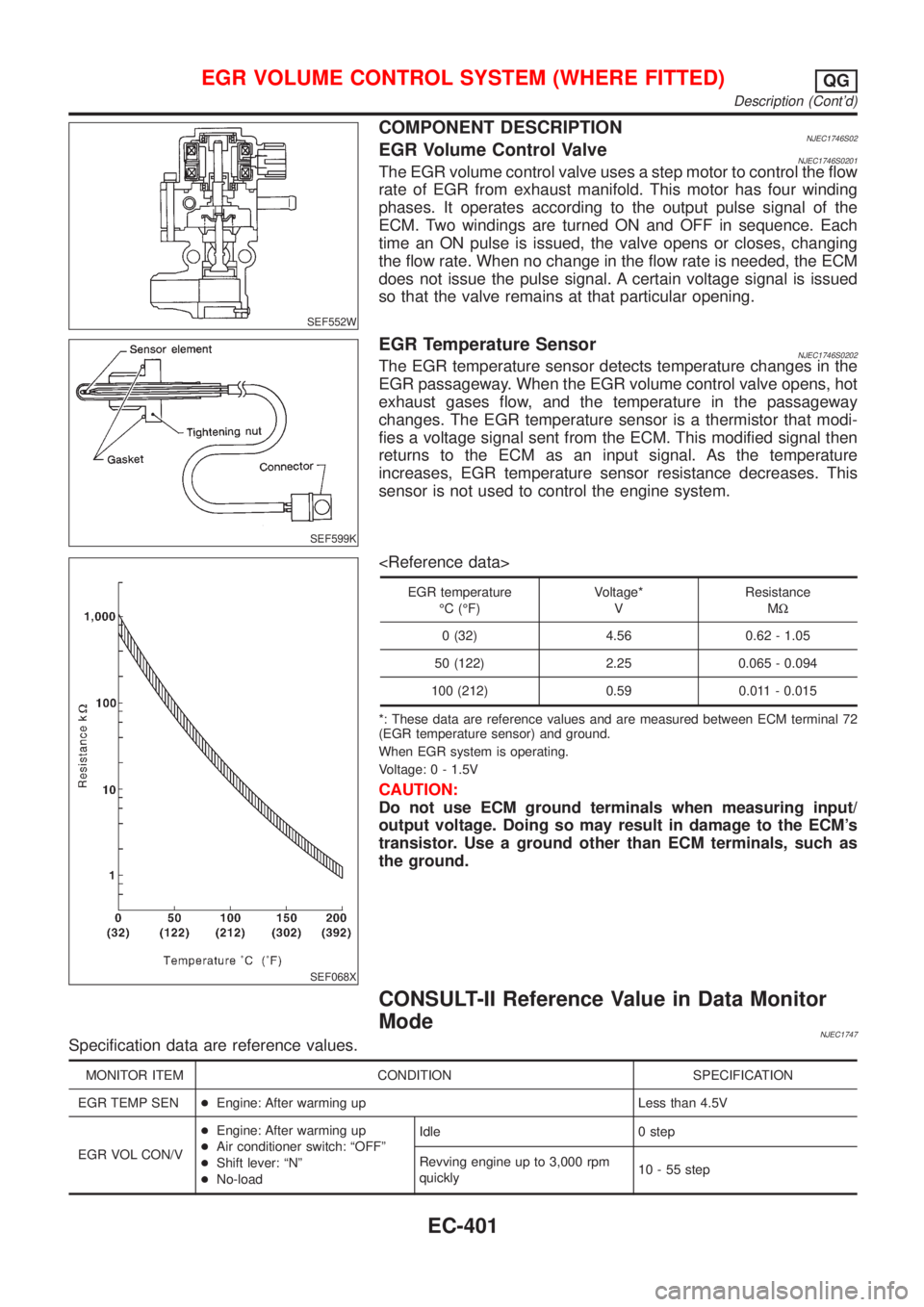
COMPONENT DESCRIPTIONNJEC1746S02EGR Volume Control ValveNJEC1746S0201The EGR volume control valve uses a step motor to control the flow
rate of EGR from exhaust manifold. This motor has four winding
phases. It operates according to the output pulse signal of the
ECM. Two windings are turned ON and OFF in sequence. Each
time an ON pulse is issued, the valve opens or closes, changing
the flow rate. When no change in the flow rate is needed, the ECM
does not issue the pulse signal. A certain voltage signal is issued
so that the valve remains at that particular opening.
SEF599K
EGR Temperature SensorNJEC1746S0202The EGR temperature sensor detects temperature changes in the
EGR passageway. When the EGR volume control valve opens, hot
exhaust gases flow, and the temperature in the passageway
changes. The EGR temperature sensor is a thermistor that modi-
fies a voltage signal sent from the ECM. This modified signal then
returns to the ECM as an input signal. As the temperature
increases, EGR temperature sensor resistance decreases. This
sensor is not used to control the engine system.
SEF068X
EGR temperature
ÉC (ÉF)Voltage*
VResistance
MW
0 (32) 4.56 0.62 - 1.05
50 (122) 2.25 0.065 - 0.094
100 (212) 0.59 0.011 - 0.015
*: These data are reference values and are measured between ECM terminal 72
(EGR temperature sensor) and ground.
When EGR system is operating.
Voltage: 0 - 1.5V
CAUTION:
Do not use ECM ground terminals when measuring input/
output voltage. Doing so may result in damage to the ECM's
transistor. Use a ground other than ECM terminals, such as
the ground.
CONSULT-II Reference Value in Data Monitor
Mode
NJEC1747Specification data are reference values.
MONITOR ITEM CONDITION SPECIFICATION
EGR TEMP SEN+Engine: After warming up Less than 4.5V
EGR VOL CON/V+Engine: After warming up
+Air conditioner switch: ªOFFº
+Shift lever: ªNº
+No-loadIdle 0 step
Revving engine up to 3,000 rpm
quickly10 - 55 step
EGR VOLUME CONTROL SYSTEM (WHERE FITTED)QG
Description (Cont'd)
EC-401
Page 714 of 2493
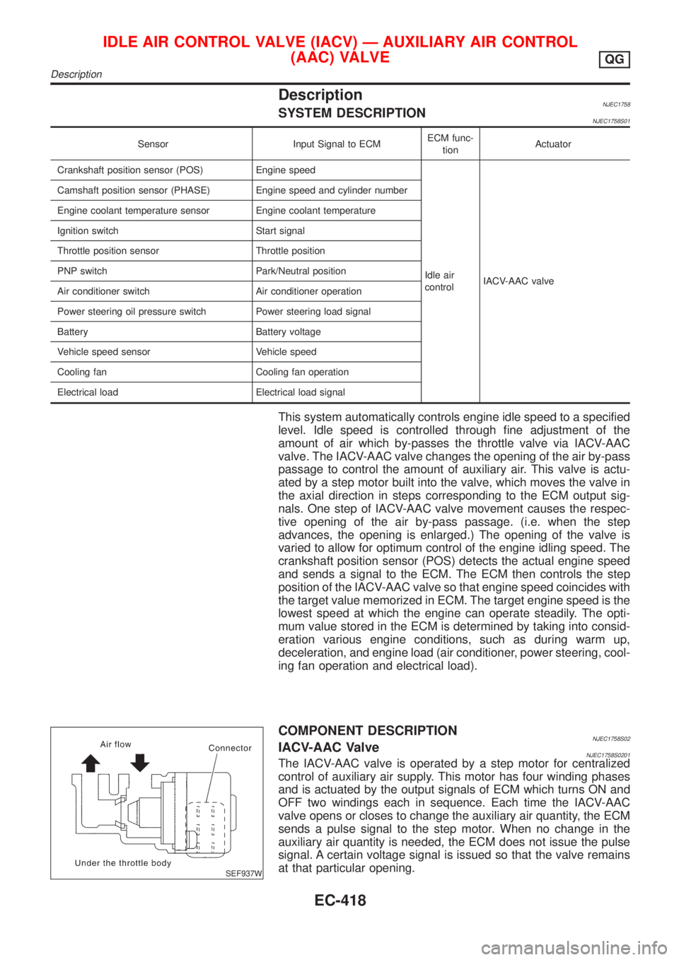
DescriptionNJEC1758SYSTEM DESCRIPTIONNJEC1758S01
Sensor Input Signal to ECMECM func-
tionActuator
Crankshaft position sensor (POS) Engine speed
Idle air
controlIACV-AAC valve Camshaft position sensor (PHASE) Engine speed and cylinder number
Engine coolant temperature sensor Engine coolant temperature
Ignition switch Start signal
Throttle position sensor Throttle position
PNP switch Park/Neutral position
Air conditioner switch Air conditioner operation
Power steering oil pressure switch Power steering load signal
Battery Battery voltage
Vehicle speed sensor Vehicle speed
Cooling fan Cooling fan operation
Electrical load Electrical load signal
This system automatically controls engine idle speed to a specified
level. Idle speed is controlled through fine adjustment of the
amount of air which by-passes the throttle valve via IACV-AAC
valve. The IACV-AAC valve changes the opening of the air by-pass
passage to control the amount of auxiliary air. This valve is actu-
ated by a step motor built into the valve, which moves the valve in
the axial direction in steps corresponding to the ECM output sig-
nals. One step of IACV-AAC valve movement causes the respec-
tive opening of the air by-pass passage. (i.e. when the step
advances, the opening is enlarged.) The opening of the valve is
varied to allow for optimum control of the engine idling speed. The
crankshaft position sensor (POS) detects the actual engine speed
and sends a signal to the ECM. The ECM then controls the step
position of the IACV-AAC valve so that engine speed coincides with
the target value memorized in ECM. The target engine speed is the
lowest speed at which the engine can operate steadily. The opti-
mum value stored in the ECM is determined by taking into consid-
eration various engine conditions, such as during warm up,
deceleration, and engine load (air conditioner, power steering, cool-
ing fan operation and electrical load).
SEF937W
COMPONENT DESCRIPTIONNJEC1758S02IACV-AAC ValveNJEC1758S0201The IACV-AAC valve is operated by a step motor for centralized
control of auxiliary air supply. This motor has four winding phases
and is actuated by the output signals of ECM which turns ON and
OFF two windings each in sequence. Each time the IACV-AAC
valve opens or closes to change the auxiliary air quantity, the ECM
sends a pulse signal to the step motor. When no change in the
auxiliary air quantity is needed, the ECM does not issue the pulse
signal. A certain voltage signal is issued so that the valve remains
at that particular opening.
IDLE AIR CONTROL VALVE (IACV) Ð AUXILIARY AIR CONTROL
(AAC) VALVE
QG
Description
EC-418
Page 802 of 2493
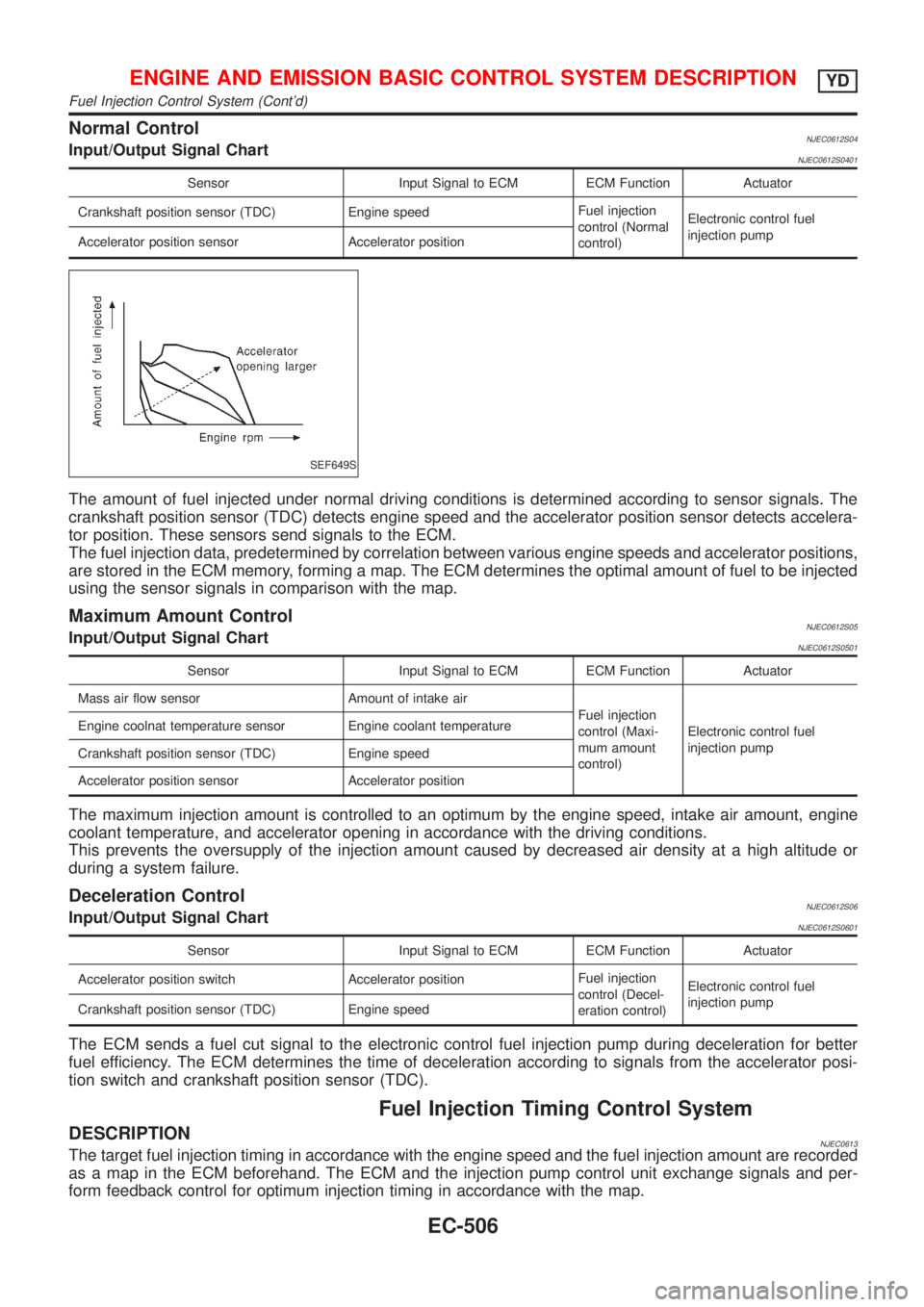
Normal ControlNJEC0612S04Input/Output Signal ChartNJEC0612S0401
Sensor Input Signal to ECM ECM Function Actuator
Crankshaft position sensor (TDC) Engine speedFuel injection
control (Normal
control)Electronic control fuel
injection pump
Accelerator position sensor Accelerator position
SEF649S
The amount of fuel injected under normal driving conditions is determined according to sensor signals. The
crankshaft position sensor (TDC) detects engine speed and the accelerator position sensor detects accelera-
tor position. These sensors send signals to the ECM.
The fuel injection data, predetermined by correlation between various engine speeds and accelerator positions,
are stored in the ECM memory, forming a map. The ECM determines the optimal amount of fuel to be injected
using the sensor signals in comparison with the map.
Maximum Amount ControlNJEC0612S05Input/Output Signal ChartNJEC0612S0501
Sensor Input Signal to ECM ECM Function Actuator
Mass air flow sensor Amount of intake air
Fuel injection
control (Maxi-
mum amount
control)Electronic control fuel
injection pump Engine coolnat temperature sensor Engine coolant temperature
Crankshaft position sensor (TDC) Engine speed
Accelerator position sensor Accelerator position
The maximum injection amount is controlled to an optimum by the engine speed, intake air amount, engine
coolant temperature, and accelerator opening in accordance with the driving conditions.
This prevents the oversupply of the injection amount caused by decreased air density at a high altitude or
during a system failure.
Deceleration ControlNJEC0612S06Input/Output Signal ChartNJEC0612S0601
Sensor Input Signal to ECM ECM Function Actuator
Accelerator position switch Accelerator positionFuel injection
control (Decel-
eration control)Electronic control fuel
injection pump
Crankshaft position sensor (TDC) Engine speed
The ECM sends a fuel cut signal to the electronic control fuel injection pump during deceleration for better
fuel efficiency. The ECM determines the time of deceleration according to signals from the accelerator posi-
tion switch and crankshaft position sensor (TDC).
Fuel Injection Timing Control System
DESCRIPTIONNJEC0613The target fuel injection timing in accordance with the engine speed and the fuel injection amount are recorded
as a map in the ECM beforehand. The ECM and the injection pump control unit exchange signals and per-
form feedback control for optimum injection timing in accordance with the map.
ENGINE AND EMISSION BASIC CONTROL SYSTEM DESCRIPTIONYD
Fuel Injection Control System (Cont'd)
EC-506
Page 818 of 2493
DTC and MI Detection LogicNJEC0626When a malfunction is detected, the malfunction (DTC) is stored in the ECM memory.
The MI will light up each time the ECM detects malfunction. For diagnostic items causing the MI to light up,
refer to ªTROUBLE DIAGNOSIS Ð INDEXº, EC-492.
Diagnostic Trouble Code (DTC)NJEC0627HOW TO READ DTCNJEC0627S01The DTC can be read by the following methods.
Without CONSULT-II
ECM displays the DTC by a set of four digit numbers with MI illumination in the diagnostic test mode II (Self-
diagnostic results). Example: 0103, 0807, 1002, etc.
With CONSULT-II
CONSULT-II displays the DTC in ªSELF-DIAG RESULTSº mode. Examples: P0115, P0571, P1202, etc.
These DTCs are prescribed by ISO15031-6.
(CONSULT-II also displays the malfunctioning component or system.)
+Output of the trouble code means that the indicated circuit has a malfunction. However, in the Mode
II it does not indicate whether the malfunction is still occurring or occurred in the past and returned
to normal.
CONSULT-II can identify them. Therefore, using CONSULT-II (if available) is recommended.
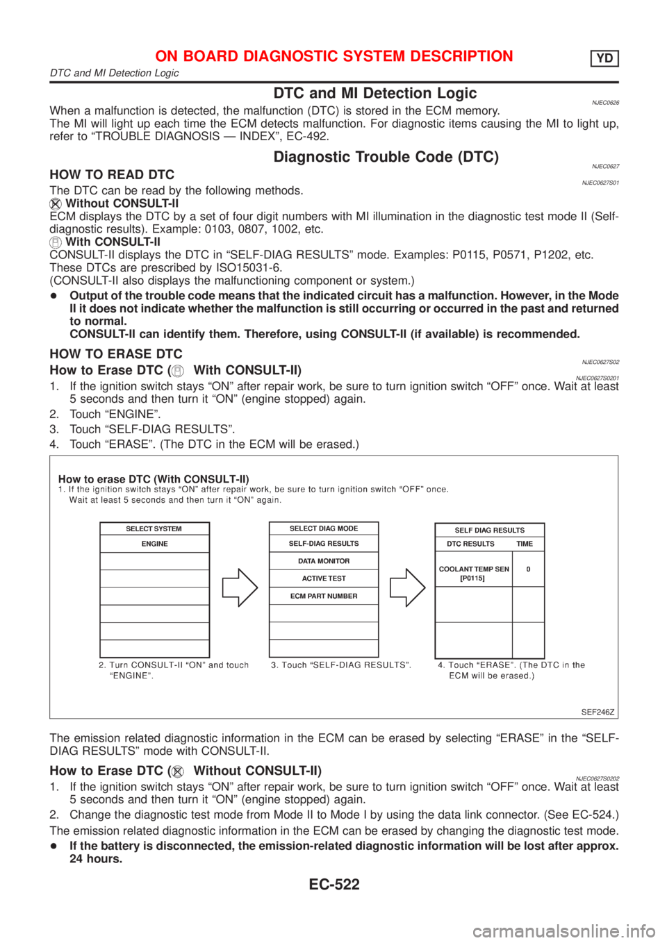
HOW TO ERASE DTCNJEC0627S02How to Erase DTC (With CONSULT-II)NJEC0627S02011. If the ignition switch stays ªONº after repair work, be sure to turn ignition switch ªOFFº once. Wait at least
5 seconds and then turn it ªONº (engine stopped) again.
2. Touch ªENGINEº.
3. Touch ªSELF-DIAG RESULTSº.
4. Touch ªERASEº. (The DTC in the ECM will be erased.)
SEF246Z
The emission related diagnostic information in the ECM can be erased by selecting ªERASEº in the ªSELF-
DIAG RESULTSº mode with CONSULT-II.
How to Erase DTC (Without CONSULT-II)NJEC0627S02021. If the ignition switch stays ªONº after repair work, be sure to turn ignition switch ªOFFº once. Wait at least
5 seconds and then turn it ªONº (engine stopped) again.
2. Change the diagnostic test mode from Mode II to Mode I by using the data link connector. (See EC-524.)
The emission related diagnostic information in the ECM can be erased by changing the diagnostic test mode.
+If the battery is disconnected, the emission-related diagnostic information will be lost after approx.
24 hours.
ON BOARD DIAGNOSTIC SYSTEM DESCRIPTIONYD
DTC and MI Detection Logic
EC-522
Page 821 of 2493
Diagnostic Test Mode I Ð Bulb CheckNJEC0628S03In this mode, the MI on the instrument panel should stay ON. If it remains OFF, check the bulb. Refer to EL-107,
ªWARNING LAMPSº or see EC-701.
Diagnostic Test Mode I Ð Malfunction WarningNJEC0628S04
MI Condition
ON When the malfunction is detected or the ECM's CPU is malfunctioning.
OFF No malfunction.
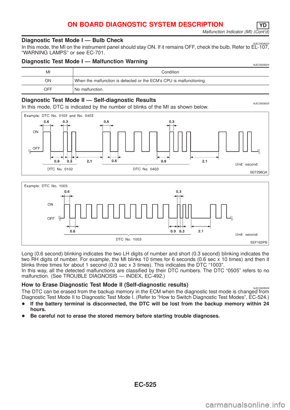
Diagnostic Test Mode II Ð Self-diagnostic ResultsNJEC0628S05In this mode, DTC is indicated by the number of blinks of the MI as shown below.
SEF298QA
SEF162PB
Long (0.6 second) blinking indicates the two LH digits of number and short (0.3 second) blinking indicates the
two RH digits of number. For example, the MI blinks 10 times for 6 seconds (0.6 sec x 10 times) and then it
blinks three times for about 1 second (0.3 sec x 3 times). This indicates the DTC ª1003º.
In this way, all the detected malfunctions are classified by their DTC numbers. The DTC ª0505º refers to no
malfunction. (See TROUBLE DIAGNOSIS Ð INDEX, EC-492.)
How to Erase Diagnostic Test Mode II (Self-diagnostic results)NJEC0628S06The DTC can be erased from the backup memory in the ECM when the diagnostic test mode is changed from
Diagnostic Test Mode II to Diagnostic Test Mode I. (Refer to ªHow to Switch Diagnostic Test Modesº, EC-524.)
+If the battery terminal is disconnected, the DTC will be lost from the backup memory within 24
hours.
+Be careful not to erase the stored memory before starting trouble diagnoses.
ON BOARD DIAGNOSTIC SYSTEM DESCRIPTIONYD
Malfunction Indicator (MI) (Cont'd)
EC-525
Page 826 of 2493
ACTIVE TEST MODENJEC0629S05
TEST ITEM CONDITION JUDGEMENT CHECK ITEM (REMEDY)
COOLING FAN+Ignition switch: ON
+Operate the cooling fan at
ªLOWº, ªHIº speed and turn
ªOFFº using CONSULT-II.Cooling fan moves at ªLOWº, ªHIº
speed and stops.+Harness and connector
+Cooling fan motor
+Cooling fan relay
EGR VOL
CONT/V+Ignition switch: ON
+Change EGR volume control
valve opening step using CON-
SULT-II.EGR volume control valve makes
an operating sound.+Harness and connector
+EGR volume control valve
GLOW RLY+Ignition switch: ON (Engine
stopped)
+Turn the glow relay ªONº and
ªOFFº using CONSULT-II and
listen to operating sound.Glow relay makes the operating
sound.+Harness and connector
+Glow relay
SEF373Y
SEF707X
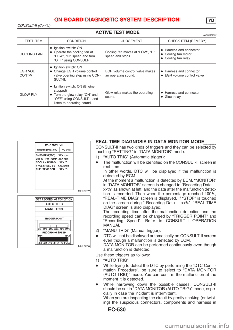
REAL TIME DIAGNOSIS IN DATA MONITOR MODENJEC0629S06CONSULT-II has two kinds of triggers and they can be selected by
touching ªSETTINGº in ªDATA MONITORº mode.
1) ªAUTO TRIGº (Automatic trigger):
+The malfunction will be identified on the CONSULT-II screen in
real time.
In other words, DTC will be displayed if the malfunction is
detected by ECM.
At the moment a malfunction is detected by ECM, ªMONITORº
in ªDATA MONITORº screen is changed to ªRecording Data ...
xx%º as shown at left, and the data after the malfunction detec-
tion is recorded. Then when the percentage reached 100%,
ªREAL-TIME DIAGº screen is displayed. If ªSTOPº is touched
on the screen during ª Recording Data ... xx%º, ªREAL-TIME
DIAGº screen is also displayed.
The recording time after the malfunction detection and the
recording speed can be changed by ªTRIGGER POINTº and
ªRecording Speedº. Refer to CONSULT-II OPERATION
MANUAL.
2) ªMANU TRIGº (Manual trigger):
+DTC will not be displayed automatically on CONSULT-II screen
even though a malfunction is detected by ECM.
DATA MONITOR can be performed continuously even though
a malfunction is detected.
Use these triggers as follows:
1) ªAUTO TRIGº
+While trying to detect the DTC by performing the ªDTC Confir-
mation Procedureº, be sure to select to ªDATA MONITOR
(AUTO TRIG)º mode. You can confirm the malfunction at the
moment it is detected.
+While narrowing down the possible causes, CONSULT-II
should be set in ªDATA MONITOR (AUTO TRIG)º mode, espe-
cially in case the incident is intermittent.
When you are inspecting the circuit by gently shaking (or twist-
ing) the suspicious connectors, components and harness in
ON BOARD DIAGNOSTIC SYSTEM DESCRIPTIONYD
CONSULT-II (Cont'd)
EC-530