2001 NISSAN ALMERA N16 change time
[x] Cancel search: change timePage 2051 of 2493
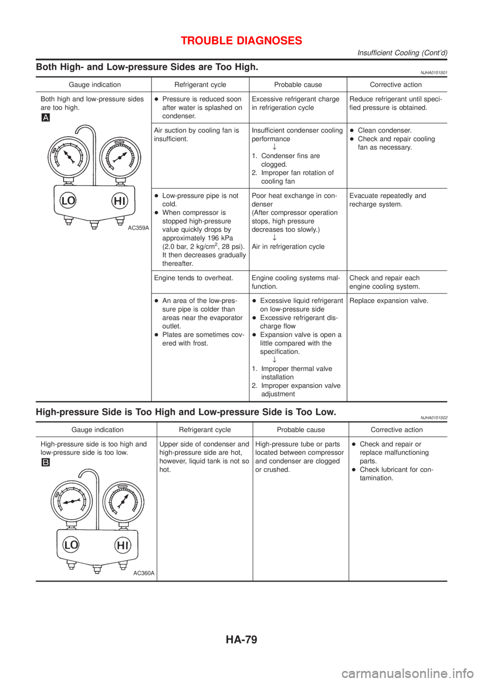
Both High- and Low-pressure Sides are Too High.NJHA0151S01
Gauge indication Refrigerant cycle Probable cause Corrective action
Both high and low-pressure sides
are too high.
AC359A
+Pressure is reduced soon
after water is splashed on
condenser.Excessive refrigerant charge
in refrigeration cycleReduce refrigerant until speci-
fied pressure is obtained.
Air suction by cooling fan is
insufficient.Insufficient condenser cooling
performance
¯
1. Condenser fins are
clogged.
2. Improper fan rotation of
cooling fan+Clean condenser.
+Check and repair cooling
fan as necessary.
+Low-pressure pipe is not
cold.
+When compressor is
stopped high-pressure
value quickly drops by
approximately 196 kPa
(2.0 bar, 2 kg/cm
2, 28 psi).
It then decreases gradually
thereafter.Poor heat exchange in con-
denser
(After compressor operation
stops, high pressure
decreases too slowly.)
¯
Air in refrigeration cycleEvacuate repeatedly and
recharge system.
Engine tends to overheat. Engine cooling systems mal-
function.Check and repair each
engine cooling system.
+An area of the low-pres-
sure pipe is colder than
areas near the evaporator
outlet.
+Plates are sometimes cov-
ered with frost.+Excessive liquid refrigerant
on low-pressure side
+Excessive refrigerant dis-
charge flow
+Expansion valve is open a
little compared with the
specification.
¯
1. Improper thermal valve
installation
2. Improper expansion valve
adjustmentReplace expansion valve.
High-pressure Side is Too High and Low-pressure Side is Too Low.NJHA0151S02
Gauge indication Refrigerant cycle Probable cause Corrective action
High-pressure side is too high and
low-pressure side is too low.
AC360A
Upper side of condenser and
high-pressure side are hot,
however, liquid tank is not so
hot.High-pressure tube or parts
located between compressor
and condenser are clogged
or crushed.+Check and repair or
replace malfunctioning
parts.
+Check lubricant for con-
tamination.
TROUBLE DIAGNOSES
Insufficient Cooling (Cont'd)
HA-79
Page 2201 of 2493
Component Parts and Harness Connector
Location
NJEL0441For details, refer to ªELECTRICAL UNIT LOCATIONº (EL-319) and
ªHARNESS LAYOUTº (EL-324).
System DescriptionNJEL0442UNIFIED CONTROL METERNJEL0442S01+Speedometer, odo/trip meter, tachometer, fuel gauge and water temperature gauge are controlled totally
by control unit built-in combination meter.
+Digital meter is adopted for odo/trip meter.*
*The record of the odo meter is kept even if the battery cable is disconnected. The record of the trip meter
is erased when the battery cable is disconnected.
+Odo/trip meter segment can be checked in diagnosis mode.
+Meter/gauge can be checked in diagnosis mode.
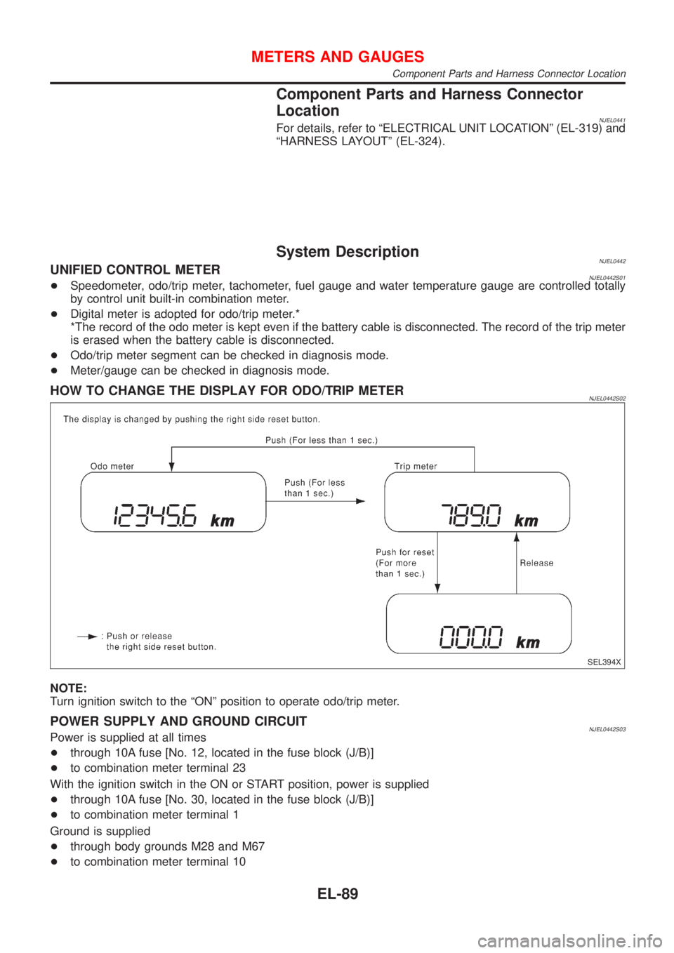
HOW TO CHANGE THE DISPLAY FOR ODO/TRIP METERNJEL0442S02
SEL394X
NOTE:
Turn ignition switch to the ªONº position to operate odo/trip meter.
POWER SUPPLY AND GROUND CIRCUITNJEL0442S03Power is supplied at all times
+through 10A fuse [No. 12, located in the fuse block (J/B)]
+to combination meter terminal 23
With the ignition switch in the ON or START position, power is supplied
+through 10A fuse [No. 30, located in the fuse block (J/B)]
+to combination meter terminal 1
Ground is supplied
+through body grounds M28 and M67
+to combination meter terminal 10
METERS AND GAUGES
Component Parts and Harness Connector Location
EL-89
Page 2261 of 2493
System Description=NJEL0497Refer to Owner's Manual for audio system operating instructions.
Power is supplied at all times
+through 15A fuse (No. 32, located in the fusible link and fuse block)
+to audio unit terminal 9
+to CD auto changer terminal 32.
With the ignition switch in the ACC or ON position, power is supplied
+through 10A fuse [No. 1, located in the fuse block (J/B)]
+to audio unit terminal 3,
+to CD auto changer terminal 36 and
Ground is supplied through the case of the audio unit.
Audio signals are supplied
+through audio unit terminals 7, 10, 11, 12, 13, 14, 15, 16
+to terminals 1 and 2 of front door speaker LH and RH,
+to terminals 1 and 2 of rear door speaker LH and RH and
+to terminals 1 and 2 of pillar tweeter LH and RH (with 6 speakers)
When the navigation system is triggered,
power is supplied
+through navi control unit terminal 46
+to speaker relay terminal 2
Ground is supplied
+through navi control unit terminal 44
+to speaker relay terminal 1
With power and ground supplied, the relay is energized, and then audio signal is interrupted to front door
speaker LH (LHD models) or RH (RHD models), and pillar tweeter LH (LHD models) or RH (RHD models)
For detailed, refer to ªNAVIGATION SYSTEMº.
NATS AUDIO LINKNJEL0497S01DescriptionNJEL0497S0101The link with the NATS IMMU implies that the audio unit can basically only be operated if connected to the
matching NATS IMMU to which the audio unit was initially fitted on the production line.
Since radio operation is impossible after the link with the NATS is disrupted theft of the audio unit is basically
useless since special equipment is required to reset the audio unit.
Initialization process for audio units that are linked to the NATS IMMU
New audio units will be delivered to the factories in the ªNEWº state, i.e. ready to be linked with the vehicle's
NATS. When the audio unit in ªNEWº state is first switched on at the factory, it will start up communication
with the vehicle's immobiliser control unit (IMMU) and send a code (the ªaudio unit Codeº) to the IMMU. The
IMMU will then store this code, which is unique to each audio unit, in its (permanent) memory.
Upon receipt of the code by the IMMU, the NATS will confirm correct receipt of the audio unit code to the audio
unit. Hereafter, the audio unit will operate as normal.
During the initialisation process, ªNEWº is displayed on the audio unit display. Normally though, communica-
tion between audio unit and IMMU takes such a short time (300 ms) that the audio unit seems to switch on
directly without showing ªNEWº on its display.
Normal operation
Each time the audio unit is switched on afterwards, the audio unit code will be verified between the audio unit
and the NATS before the audio unit becomes operational. During the code verification process, ªWAITº is
shown on the audio unit display. Again, the communication takes such a short time (300 ms) that the audio
unit seems to switch on directly without showing ªWAITº on its display.
When the radio is locked
In case of a audio unit being linked with the vehicle's NATS (immobilizer system), disconnection of the link
between the audio unit and the IMMU will cause the audio unit to switch into the lock (ªSECUREº) mode in
which the audio unit is fully inoperative. Hence, repair of the audio unit is basically impossible, unless the audio
unit is reset to the ªNEWº state for which special decoding equipment is required.
Clarion has provided their authorized service representatives with so called ªdecoder boxesº which can bring
the audio unit back to the ªNEWº state, enabling the audio unit to be switched on after which repair can be
AUDIO
System Description
EL-149
Page 2343 of 2493
USER ACTION TCU Reaction COMPONENT TESTED
Lighting switch turned 1st position or 2nd
position from offHazard flash once Tail lamp signal
Key put in ignition from out Hazard flash once Key in detect signal
Door lock/unlock switch is pressed Hazard flash once Central door lock/unlock signal
*) Hazard may flash a second time because of Driver's door status signal change. The min. delay time between flash actions is 100
ms.
In case the system does not operate as described above, check the concerned circuit for open or short. After
completion, the Diagnostic Mode can be switched off by pressing the rear defogger switch or by turning the
ignition to ªONº. The hazard lamp will flash at 3 Hz for 3 seconds to confirm that Diagnostic Mode has been
switched off.
TIME CONTROL UNIT
Trouble Diagnoses (Cont'd)
EL-231
Page 2373 of 2493
SEL504X
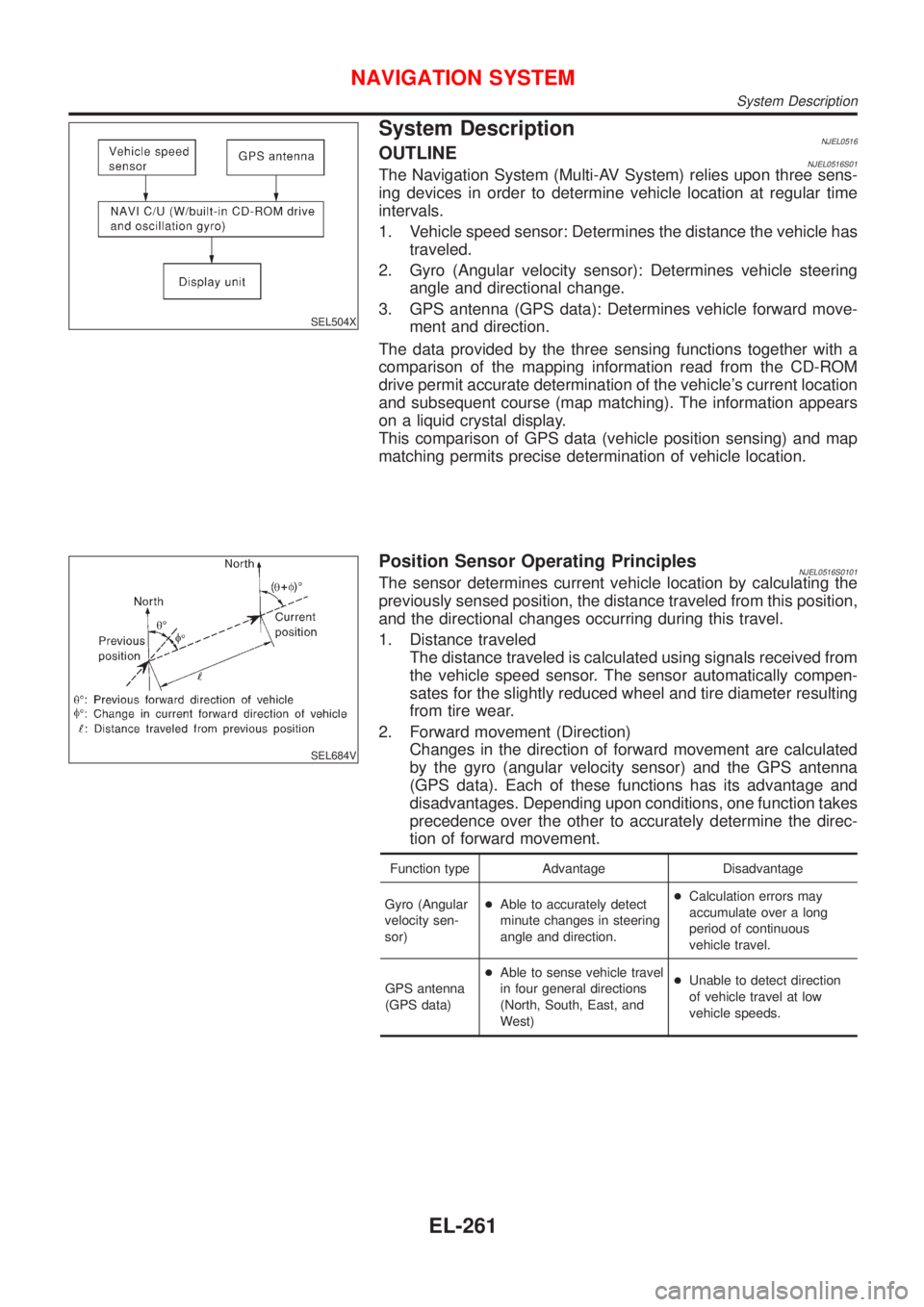
System DescriptionNJEL0516OUTLINENJEL0516S01The Navigation System (Multi-AV System) relies upon three sens-
ing devices in order to determine vehicle location at regular time
intervals.
1. Vehicle speed sensor: Determines the distance the vehicle has
traveled.
2. Gyro (Angular velocity sensor): Determines vehicle steering
angle and directional change.
3. GPS antenna (GPS data): Determines vehicle forward move-
ment and direction.
The data provided by the three sensing functions together with a
comparison of the mapping information read from the CD-ROM
drive permit accurate determination of the vehicle's current location
and subsequent course (map matching). The information appears
on a liquid crystal display.
This comparison of GPS data (vehicle position sensing) and map
matching permits precise determination of vehicle location.
SEL684V
Position Sensor Operating PrinciplesNJEL0516S0101The sensor determines current vehicle location by calculating the
previously sensed position, the distance traveled from this position,
and the directional changes occurring during this travel.
1. Distance traveled
The distance traveled is calculated using signals received from
the vehicle speed sensor. The sensor automatically compen-
sates for the slightly reduced wheel and tire diameter resulting
from tire wear.
2. Forward movement (Direction)
Changes in the direction of forward movement are calculated
by the gyro (angular velocity sensor) and the GPS antenna
(GPS data). Each of these functions has its advantage and
disadvantages. Depending upon conditions, one function takes
precedence over the other to accurately determine the direc-
tion of forward movement.
Function type Advantage Disadvantage
Gyro (Angular
velocity sen-
sor)+Able to accurately detect
minute changes in steering
angle and direction.+Calculation errors may
accumulate over a long
period of continuous
vehicle travel.
GPS antenna
(GPS data)+Able to sense vehicle travel
in four general directions
(North, South, East, and
West)+Unable to detect direction
of vehicle travel at low
vehicle speeds.
NAVIGATION SYSTEM
System Description
EL-261
Page 2374 of 2493
SEL685V
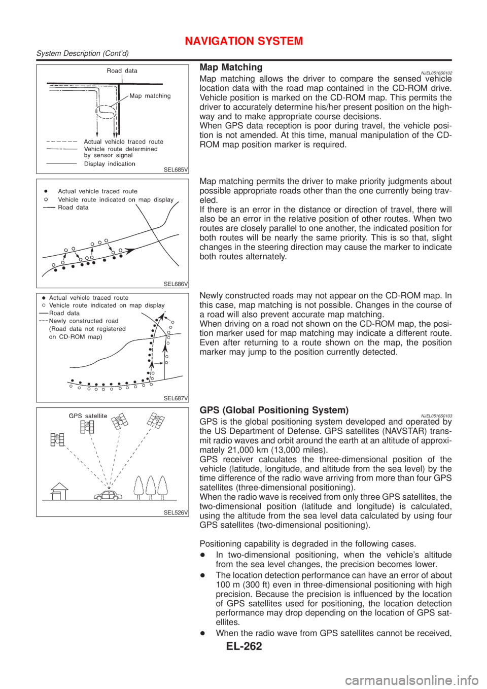
Map MatchingNJEL0516S0102Map matching allows the driver to compare the sensed vehicle
location data with the road map contained in the CD-ROM drive.
Vehicle position is marked on the CD-ROM map. This permits the
driver to accurately determine his/her present position on the high-
way and to make appropriate course decisions.
When GPS data reception is poor during travel, the vehicle posi-
tion is not amended. At this time, manual manipulation of the CD-
ROM map position marker is required.
SEL686V
Map matching permits the driver to make priority judgments about
possible appropriate roads other than the one currently being trav-
eled.
If there is an error in the distance or direction of travel, there will
also be an error in the relative position of other routes. When two
routes are closely parallel to one another, the indicated position for
both routes will be nearly the same priority. This is so that, slight
changes in the steering direction may cause the marker to indicate
both routes alternately.
SEL687V
Newly constructed roads may not appear on the CD-ROM map. In
this case, map matching is not possible. Changes in the course of
a road will also prevent accurate map matching.
When driving on a road not shown on the CD-ROM map, the posi-
tion marker used for map matching may indicate a different route.
Even after returning to a route shown on the map, the position
marker may jump to the position currently detected.
SEL526V
GPS (Global Positioning System)NJEL0516S0103GPS is the global positioning system developed and operated by
the US Department of Defense. GPS satellites (NAVSTAR) trans-
mit radio waves and orbit around the earth at an altitude of approxi-
mately 21,000 km (13,000 miles).
GPS receiver calculates the three-dimensional position of the
vehicle (latitude, longitude, and altitude from the sea level) by the
time difference of the radio wave arriving from more than four GPS
satellites (three-dimensional positioning).
When the radio wave is received from only three GPS satellites, the
two-dimensional position (latitude and longitude) is calculated,
using the altitude from the sea level data calculated by using four
GPS satellites (two-dimensional positioning).
Positioning capability is degraded in the following cases.
+In two-dimensional positioning, when the vehicle's altitude
from the sea level changes, the precision becomes lower.
+The location detection performance can have an error of about
100 m (300 ft) even in three-dimensional positioning with high
precision. Because the precision is influenced by the location
of GPS satellites used for positioning, the location detection
performance may drop depending on the location of GPS sat-
ellites.
+When the radio wave from GPS satellites cannot be received,
NAVIGATION SYSTEM
System Description (Cont'd)
EL-262
Page 2397 of 2493
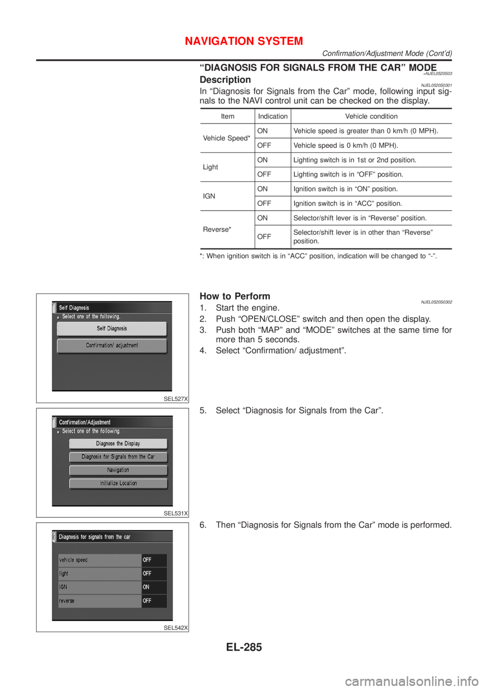
ªDIAGNOSIS FOR SIGNALS FROM THE CARº MODE=NJEL0520S03DescriptionNJEL0520S0301In ªDiagnosis for Signals from the Carº mode, following input sig-
nals to the NAVI control unit can be checked on the display.
Item Indication Vehicle condition
Vehicle Speed*ON Vehicle speed is greater than 0 km/h (0 MPH).
OFF Vehicle speed is 0 km/h (0 MPH).
LightON Lighting switch is in 1st or 2nd position.
OFF Lighting switch is in ªOFFº position.
IGNON Ignition switch is in ªONº position.
OFF Ignition switch is in ªACCº position.
Reverse*ON Selector/shift lever is in ªReverseº position.
OFFSelector/shift lever is in other than ªReverseº
position.
*: When ignition switch is in ªACCº position, indication will be changed to ª-º.
SEL527X
How to PerformNJEL0520S03021. Start the engine.
2. Push ªOPEN/CLOSEº switch and then open the display.
3. Push both ªMAPº and ªMODEº switches at the same time for
more than 5 seconds.
4. Select ªConfirmation/ adjustmentº.
SEL531X
5. Select ªDiagnosis for Signals from the Carº.
SEL542X
6. Then ªDiagnosis for Signals from the Carº mode is performed.
NAVIGATION SYSTEM
Confirmation/Adjustment Mode (Cont'd)
EL-285
Page 2401 of 2493
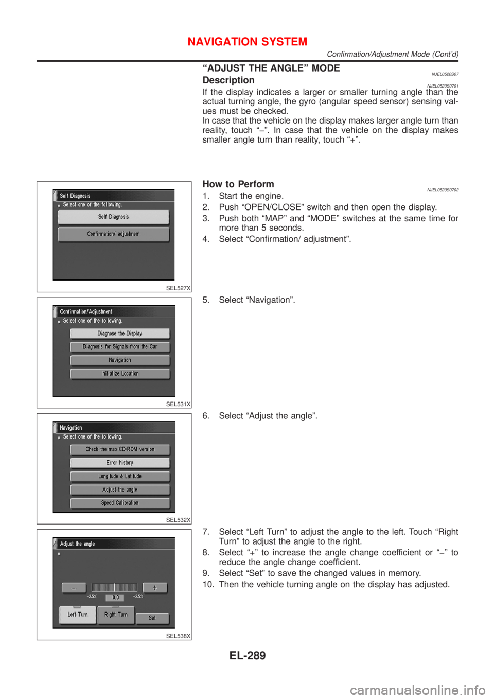
ªADJUST THE ANGLEº MODENJEL0520S07DescriptionNJEL0520S0701If the display indicates a larger or smaller turning angle than the
actual turning angle, the gyro (angular speed sensor) sensing val-
ues must be checked.
In case that the vehicle on the display makes larger angle turn than
reality, touch ªþº. In case that the vehicle on the display makes
smaller angle turn than reality, touch ª+º.
SEL527X
How to PerformNJEL0520S07021. Start the engine.
2. Push ªOPEN/CLOSEº switch and then open the display.
3. Push both ªMAPº and ªMODEº switches at the same time for
more than 5 seconds.
4. Select ªConfirmation/ adjustmentº.
SEL531X
5. Select ªNavigationº.
SEL532X
6. Select ªAdjust the angleº.
SEL538X
7. Select ªLeft Turnº to adjust the angle to the left. Touch ªRight
Turnº to adjust the angle to the right.
8. Select ª+º to increase the angle change coefficient or ªþº to
reduce the angle change coefficient.
9. Select ªSetº to save the changed values in memory.
10. Then the vehicle turning angle on the display has adjusted.
NAVIGATION SYSTEM
Confirmation/Adjustment Mode (Cont'd)
EL-289