Page 1139 of 2493

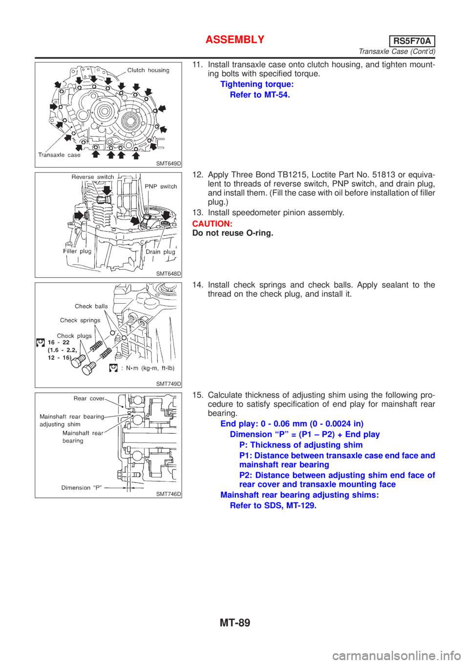
SMT649D
11. Install transaxle case onto clutch housing, and tighten mount-
ing bolts with specified torque.
Tightening torque:
Refer to MT-54.
SMT648D
12. Apply Three Bond TB1215, Loctite Part No. 51813 or equiva-
lent to threads of reverse switch, PNP switch, and drain plug,
and install them. (Fill the case with oil before installation of filler
plug.)
13. Install speedometer pinion assembly.
CAUTION:
Do not reuse O-ring.
SMT749D
14. Install check springs and check balls. Apply sealant to the
thread on the check plug, and install it.
SMT746D
15. Calculate thickness of adjusting shim using the following pro-
cedure to satisfy specification of end play for mainshaft rear
bearing.
End play: 0 - 0.06 mm (0 - 0.0024 in)
Dimension ªPº = (P1 ± P2) + End play
P: Thickness of adjusting shim
P1: Distance between transaxle case end face and
mainshaft rear bearing
P2: Distance between adjusting shim end face of
rear cover and transaxle mounting face
Mainshaft rear bearing adjusting shims:
Refer to SDS, MT-129.
ASSEMBLYRS5F70A
Transaxle Case (Cont'd)
MT-89
Page 1529 of 2493
SAT992C
Control Valve Assembly and AccumulatorsNJAT0110REMOVALNJAT0110S011. Drain ATF from transaxle.
2. Remove oil pan and gasket.
SAT064K
3. Disconnect A/T solenoid valve harness connector.
AAT265A
4. Remove stopper ring from A/T solenoid harness terminal body.
5. Remove A/T solenoid harness by pushing terminal body into
transmission case.
AAT260A
6. Remove control valve assembly by removing fixing bolts.
Bolt length, number and location:
Bolt symbol A B C
Bolt length ª!º
40.0 mm
(1.575 in)33.0 mm
(1.299 in)43.5 mm
(1.713 in)
Number of bolts 5 6 2
+Be careful not to drop manual valve and servo release
accumulator return springs.
7. Disassemble and inspect control valve assembly if necessary.
Refer to AT-354.
ON-VEHICLE SERVICE
Control Valve Assembly and Accumulators
AT-343
Page 1532 of 2493

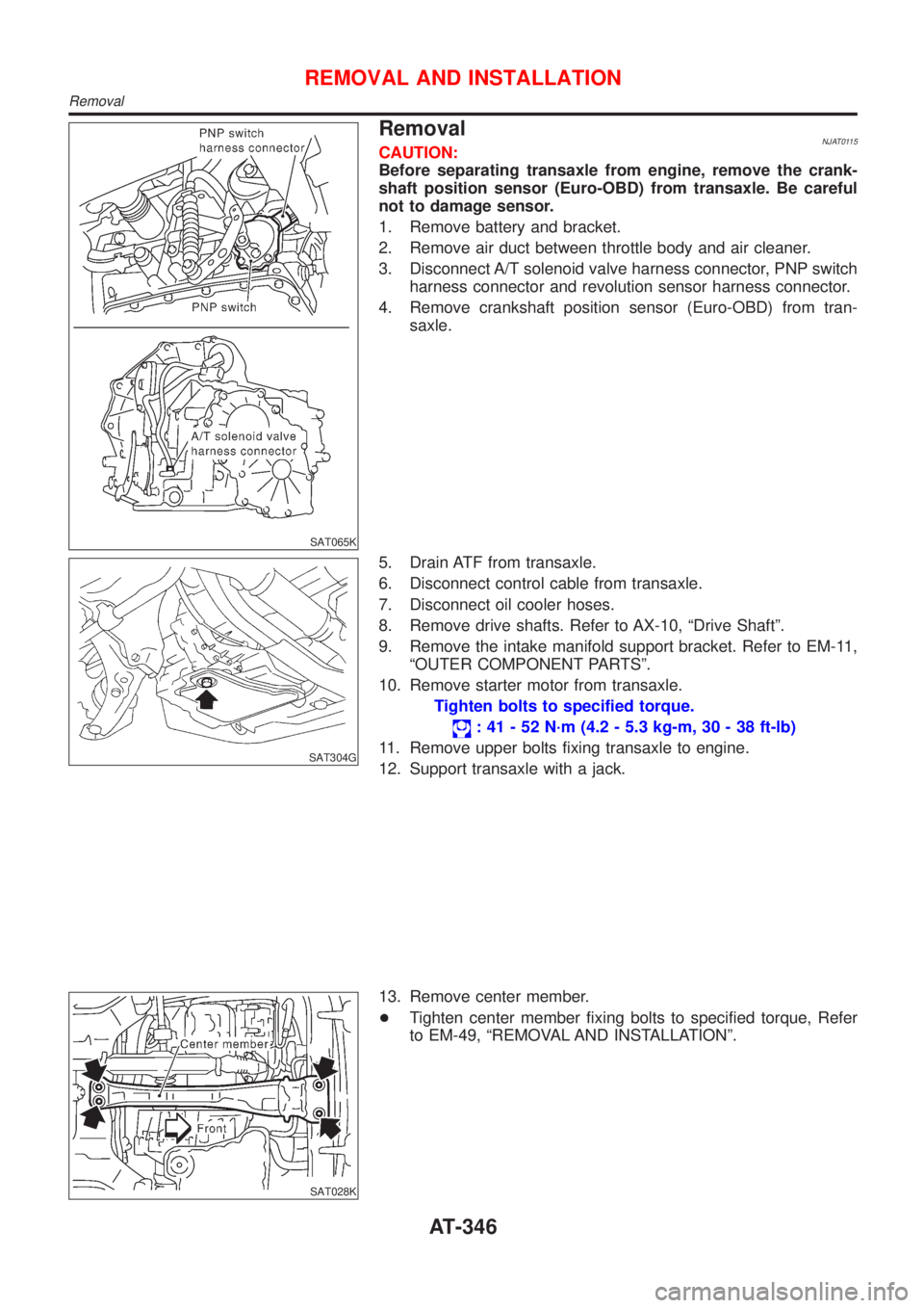
SAT065K
RemovalNJAT0115CAUTION:
Before separating transaxle from engine, remove the crank-
shaft position sensor (Euro-OBD) from transaxle. Be careful
not to damage sensor.
1. Remove battery and bracket.
2. Remove air duct between throttle body and air cleaner.
3. Disconnect A/T solenoid valve harness connector, PNP switch
harness connector and revolution sensor harness connector.
4. Remove crankshaft position sensor (Euro-OBD) from tran-
saxle.
SAT304G
5. Drain ATF from transaxle.
6. Disconnect control cable from transaxle.
7. Disconnect oil cooler hoses.
8. Remove drive shafts. Refer to AX-10, ªDrive Shaftº.
9. Remove the intake manifold support bracket. Refer to EM-11,
ªOUTER COMPONENT PARTSº.
10. Remove starter motor from transaxle.
Tighten bolts to specified torque.
: 41 - 52 N´m (4.2 - 5.3 kg-m, 30 - 38 ft-lb)
11. Remove upper bolts fixing transaxle to engine.
12. Support transaxle with a jack.
SAT028K
13. Remove center member.
+Tighten center member fixing bolts to specified torque, Refer
to EM-49, ªREMOVAL AND INSTALLATIONº.
REMOVAL AND INSTALLATION
Removal
AT-346
Page 1633 of 2493
AAT260A
d. Tighten boltsA,BandC.
:7-9N´m(0.7 - 0.9 kg-m, 61 - 78 in-lb)
Bolt length, number and location
Bolt symbolABC
Bolt length ª!º
40.0 mm
(1.575 in)33.0 mm
(1.299 in)43.5 mm
(1.713 in)
Number of bolts 5 6 2
SAT418D
8. Install oil pan.
a. Attach magnet to oil pan.
SAT128E
b. Install new oil pan gasket on transmission case.
c. Install oil pan on transmission case.
+Always replace oil pan bolts as they are self-sealing bolts.
+Tighten the four bolts in a criss-cross pattern to prevent
dislocation of gasket.
d. Tighten drain plug to specified torque.
SAT023JB
9. Install PNP switch.
a. Set manual shaft in ªPº position.
b. Temporarily install PNP switch on manual shaft.
c. Move selector lever to ªNº position.
ASSEMBLY
Assembly (4) (Cont'd)
AT-447
Page 1634 of 2493
SAT426DB
d. Usea4mm(0.157 in) pin for this adjustment.
1) Insert the pin straight into the manual shaft adjustment hole.
2) Rotate PNP switch until the pin can also be inserted straight
into hole in PNP switch.
e. Tighten PNP switch fixing bolts.
f. Remove pin from adjustment hole after adjusting PNP switch.
SAT586H
10. Install oil charging pipe and oil cooler tube to transmission
case.
SAT428DA
11. Install torque converter.
a. Pour ATF into torque converter.
+Approximately 1 liter (7/8 Imp qt) of fluid is required for a
new torque converter.
+When reusing old torque converter, add the same amount
of fluid as was drained.
SAT429D
b. Install torque converter while aligning notches of torque con-
verter with notches of oil pump.
SAT430D
c. Measure distance ªAº to check that torque converter is in
proper position.
Distance ªAº:
15.9 mm (0.626 in) or more
ASSEMBLY
Assembly (4) (Cont'd)
AT-448
Page 1693 of 2493

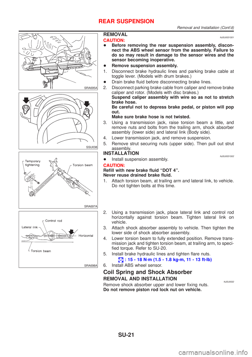
SRA695A
SSU038
REMOVALNJSU0031S01CAUTION:
+Before removing the rear suspension assembly, discon-
nect the ABS wheel sensor from the assembly. Failure to
do so may result in damage to the sensor wires and the
sensor becoming inoperative.
+Remove suspension assembly.
1. Disconnect brake hydraulic lines and parking brake cable at
toggle lever. (Models with drum brakes.)
+Drain brake fluid before disconnecting brake lines.
2. Disconnect parking brake cable from caliper and remove brake
caliper and rotor. (Models with disc brakes.)
Suspend caliper assembly with wire so as not to stretch
brake hose.
Be careful not to depress brake pedal, or piston will pop
out.
Make sure brake hose is not twisted.
3. Using a transmission jack, raise torsion beam a little, and
remove nuts and bolts from the trailing arm, shock absorber
assembly (lower side) and lateral link (Body side).
4. Lower transmission jack, and remove suspension.
5. Remove strut securing nuts (upper side). Then pull out strut
assembly.
SRA697A
INSTALLATIONNJSU0031S02+Install suspension assembly.
CAUTION:
Refill with new brake fluid ªDOT 4º.
Never reuse drained brake fluid.
1. Attach torsion beam, at trailing arm and lateral link, to vehicle.
Do not tighten bolts at this time.
SRA698A
2. Using a transmission jack, place lateral link and control rod
horizontally against torsion beam. Tighten lateral link on
vehicle.
3. Attach shock absorber assembly to vehicle. Then tighten the
lower side of shock absorber assembly.
4. Lower torsion beam to fully extended position. Remove trans-
mission jack and tighten torsion beam, at trailing arm, to speci-
fied torque. Refer to SU-20.
5. Install brake hydraulic lines and tighten flare nuts.
: 15 - 18 N´m (1.5 - 1.8 kg-m, 11 - 13 ft-lb)
6. Install ABS wheel sensor.
Coil Spring and Shock Absorber
REMOVAL AND INSTALLATIONNJSU0032Remove shock absorber upper and lower fixing nuts.
Do not remove piston rod lock nut on vehicle.
REAR SUSPENSION
Removal and Installation (Cont'd)
SU-21
Page 1708 of 2493
2. Cover openings to prevent entrance of air and dirt whenever
disconnecting brake line.
InspectionNJBR0012Check brake lines (tubes and hoses) for cracks, deterioration or
other damage. Replace any damaged parts.
SBR686C
InstallationNJBR0013CAUTION:
+Refill with new brake fluid ªDOT 4º.
+Never reuse drained brake fluid.
1. Tighten all flare nuts and connecting bolts.
Specification:
Flare nut
15 - 18 N´m (1.5 - 1.8 kg-m, 11 - 13 ft-lb)
Connecting bolt
17 - 20 N´m (1.7 - 2.0 kg-m, 12 - 14 ft-lb)
2. Refill until new brake fluid comes out of each air bleeder valve.
3. Bleed air. Refer to ªBleeding Brake Systemº, BR-8.
BRAKE HYDRAULIC LINE
Inspection
BR-10
Page 1719 of 2493
InstallationNJBR0026CAUTION:
+Be careful not to deform or bend brake pipes, during
installation of booster.
+Replace clevis pin if damaged.
+Refill with new brake fluid ªDOT 4º.
+Never reuse drained brake fluid.
+Take care not to damage brake booster mounting bolt
thread when installing. Due to the acute angle of
installation, the threads can be damaged with the dash
panel.
SBR237EA
1. Before fitting booster, temporarily adjust clevis to dimension
shown.
2. Fit booster, then secure mounting nuts (brake pedal bracket to
master cylinder) lightly.
3. Connect brake pedal and booster input rod with clevis pin.
4. Secure mounting nuts.
Specification:
13 - 16 N´m (1.3 - 1.6 kg-m,9-12ft-lb)
5. Install master cylinder. Refer to ªInstallationº in ªMASTER
CYLINDERº, BR-19.
6. Bleed air. Refer to ªBleeding Brake Systemº, BR-8.
BRAKE BOOSTER
Installation
BR-21