Page 262 of 2493
Water Pump
REMOVAL AND INSTALLATIONNJLC0018
SEM858F
SEM859F
CAUTION:
+When removing water pump assembly, be careful not to
get coolant on drive belt.
+Water pump cannot be disassembled and should be
replaced as a unit.
+After installing water pump, and check for leaks using
radiator cap tester.
1. Drain engine coolant.
Refer to LC-17, ªChanging Engine Coolantº.
2. Remove drive belts and idler pulley.
3. Loosen water pump pulley bolts.
4. Remove water pump pulley.
5. Remove front right wheel.
6. Remove front right undercover and front right fender protector.
7. Remove water pump bolts.
8. Remove water pump.
9. Reinstall parts in reverse order of removal.
SEM860F
INSPECTIONNJLC0019+Check body assembly and vane for rust or corrosion.
+Check for rough operation due to excessive end play.
ENGINE COOLING SYSTEMQG
Water Pump
LC-14
Page 281 of 2493
Oil CoolerNJLC0077
YLC015
REMOVAL AND INSTALLATIONNJLC0077S011. Draining the coolant
Refer to LC-43, ªChanging Engine Coolantº.
2. Remove the exhaust front tube.
YLC027
3. Reinstall all removed parts in the reverse order of removal.
+Confirm that no foreign objects are adhering to the installation
planes of the oil cooler or block.
+Tighten the connecting bolt after aligning the stopper on the
cylinder block side with protrusion of the oil cooler.
ENGINE LUBRICATION SYSTEMYD
Oil Cooler
LC-33
Page 287 of 2493
JLC294B
REMOVALNJLC00561. Remove the undercover, splash cover (right), and accessory
belt.
2. Drain engine coolant. Refer to LC-43, ªChanging Engine Cool-
antº.
3. Support the bottom of the oil pan with a floor jack etc., and
remove the right engine mount bracket (front side of the
engine).
4. Remove the water pump pulley.
+Loosen the pulley bolts after fixing the pulley using a screw-
driver etc.
5. Remove engine mount brackets.
6. Remove the water pump.
INSPECTIONNJLC0057+Check for rust and contamination adhering to the water pump
and vane.
+Turn the pump shaft by hand, and check that the pump turns
smoothly without looseness.
INSTALLATIONNJLC0058+Install the parts in the reverse order of removal.
+Install the water pump pulley with the front mark (painted white,
used to prevent errors during assembly) facing the front of the
engine. Refer to the figure above.
ENGINE COOLING SYSTEMYD
Water Pump (Cont'd)
LC-39
Page 1040 of 2493
ComponentsNJCL0019
YCL003
RemovalNJCL00201. Drain brake fluid.
CAUTION:
Be careful not to splash brake fluid on painted areas; it may
cause paint damage. If brake fluid is splashed on painted
areas, wash it away with water immediately.
2. Remove union bolt and clutch hose from operating cylinder.
3. Remove operating cylinder mounting bolts, and remove cylin-
der from vehicle.
DisassemblyNJCL0021Remove dust cover, and remove piston assembly from cylinder
body.
InspectionNJCL0022Inspect for following, and replace parts if necessary.
+Damage, foreign material, wear, rust, and pinholes on the cyl-
inder inner surface, piston, and sliding part of piston cup
+Weak spring
+Crack and deformation of dust cover
OPERATING CYLINDER
Components
CL-14
Page 1042 of 2493

SCL729
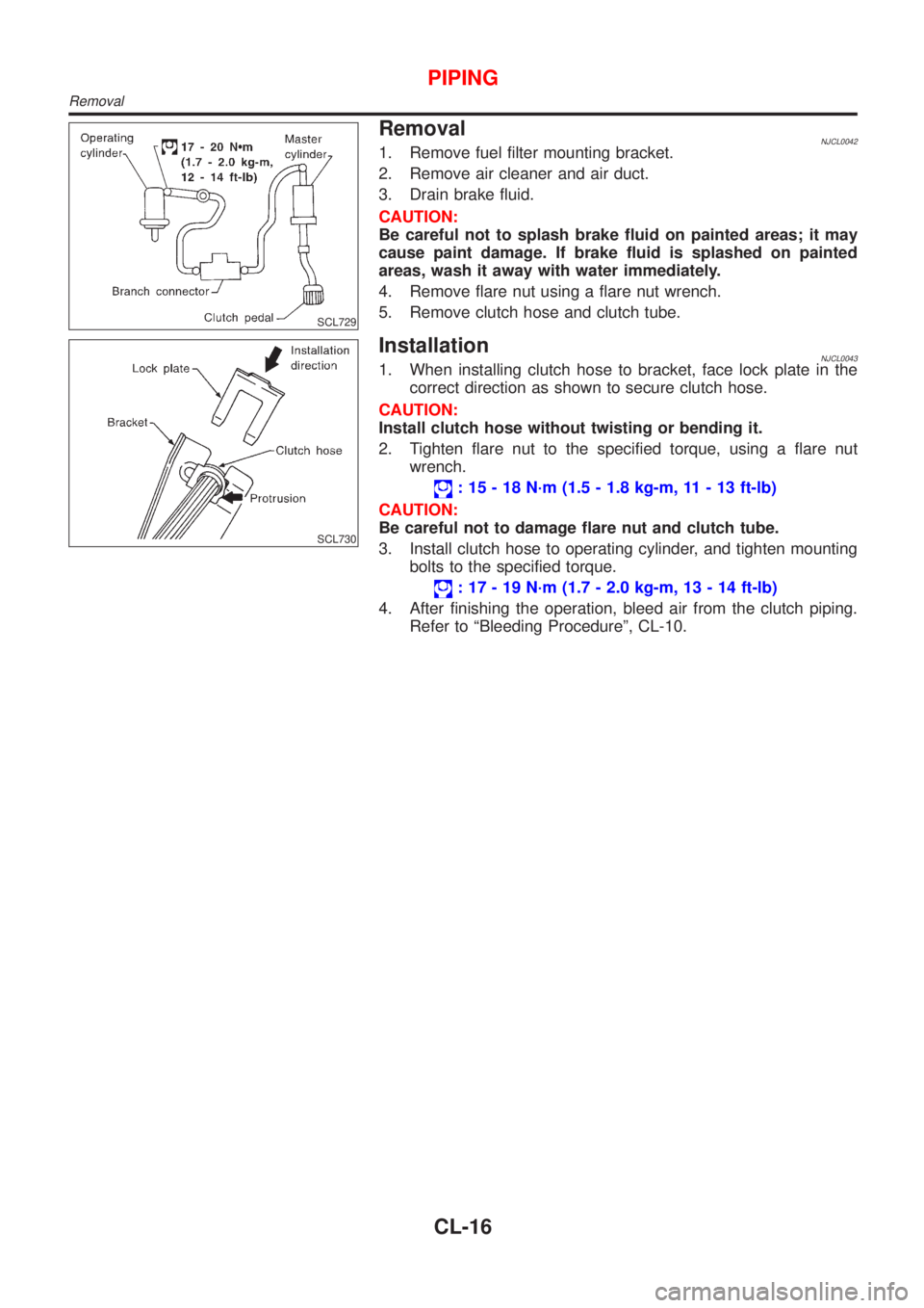
RemovalNJCL00421. Remove fuel filter mounting bracket.
2. Remove air cleaner and air duct.
3. Drain brake fluid.
CAUTION:
Be careful not to splash brake fluid on painted areas; it may
cause paint damage. If brake fluid is splashed on painted
areas, wash it away with water immediately.
4. Remove flare nut using a flare nut wrench.
5. Remove clutch hose and clutch tube.
SCL730
InstallationNJCL00431. When installing clutch hose to bracket, face lock plate in the
correct direction as shown to secure clutch hose.
CAUTION:
Install clutch hose without twisting or bending it.
2. Tighten flare nut to the specified torque, using a flare nut
wrench.
: 15 - 18 N´m (1.5 - 1.8 kg-m, 11 - 13 ft-lb)
CAUTION:
Be careful not to damage flare nut and clutch tube.
3. Install clutch hose to operating cylinder, and tighten mounting
bolts to the specified torque.
: 17 - 19 N´m (1.7 - 2.0 kg-m, 13 - 14 ft-lb)
4. After finishing the operation, bleed air from the clutch piping.
Refer to ªBleeding Procedureº, CL-10.
PIPING
Removal
CL-16
Page 1073 of 2493

NJMT0008
SMT928D
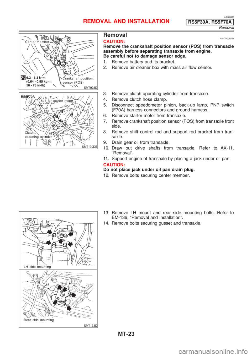
RemovalNJMT0008S01CAUTION:
Remove the crankshaft position sensor (POS) from transaxle
assembly before separating transaxle from engine.
Be careful not to damage sensor edge.
1. Remove battery and its bracket.
2. Remove air cleaner box with mass air flow sensor.
SMT130DB
3. Remove clutch operating cylinder from transaxle.
4. Remove clutch hose clamp.
5. Disconnect speedometer pinion, back-up lamp, PNP switch
(F70A) harness connectors and ground harness.
6. Remove starter motor from transaxle.
7. Remove crankshaft position sensor (POS) from transaxle front
side.
8. Remove shift control rod and support rod bracket from tran-
saxle.
9. Drain gear oil from transaxle.
10. Draw out drive shafts from transaxle. Refer to AX-11,
ªRemovalº.
11. Support engine of transaxle by placing a jack under oil pan.
CAUTION:
Do not place jack under oil pan drain plug.
12. Remove bolts securing center member.
SMT133D
13. Remove LH mount and rear side mounting bolts. Refer to
EM-136, ªRemoval and Installationº.
14. Remove bolts securing gusset and transaxle.
REMOVAL AND INSTALLATIONRS5F30A, RS5F70A
Removal
MT-23
Page 1076 of 2493

NJMT0090
SMT928D
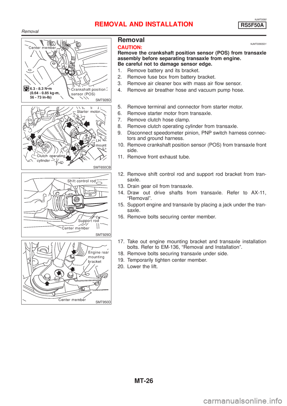
RemovalNJMT0090S01CAUTION:
Remove the crankshaft position sensor (POS) from transaxle
assembly before separating transaxle from engine.
Be careful not to damage sensor edge.
1. Remove battery and its bracket.
2. Remove fuse box from battery bracket.
3. Remove air cleaner box with mass air flow sensor.
4. Remove air breather hose and vacuum pump hose.
SMT650CB
5. Remove terminal and connector from starter motor.
6. Remove starter motor from transaxle.
7. Remove clutch hose clamp.
8. Remove clutch operating cylinder from transaxle.
9. Disconnect speedometer pinion, PNP switch harness connec-
tors and ground harness.
10. Remove crankshaft position sensor (POS) from transaxle front
side.
11. Remove front exhaust tube.
SMT929D
12. Remove shift control rod and support rod bracket from tran-
saxle.
13. Drain gear oil from transaxle.
14. Draw out drive shafts from transaxle. Refer to AX-11,
ªRemovalº.
15. Support engine and transaxle by placing a jack under the tran-
saxle.
16. Remove bolts securing center member.
SMT950D
17. Take out engine mounting bracket and transaxle installation
bolts. Refer to EM-136, ªRemoval and Installationº.
18. Remove bolts securing transaxle under side.
19. Temporarily tighten center member.
20. Lower the lift.
REMOVAL AND INSTALLATIONRS5F50A
Removal
MT-26
Page 1108 of 2493
NJMT0055
SMT648D
Transaxle CaseNJMT0055S011. Remove reverse switch, PNP switch, drain plug, and filler plug
from transaxle case.
SMT644D
2. Remove snap rings from reverse idler shaft.
3. Remove side cover and rear cover from case.
4. Remove O-ring and mainshaft bearing adjusting shim.
SMT645D
5. Remove reverse idler gear shaft.
a. Attach bolt (M6) to thread of reverse idler gear shaft end.
b. Pull out the attached bolt, and remove reverse idler gear shaft
from case.
6. Remove reverse idler gear, thrust washer (front, rear), and
bearing from case.
SMT646D
7. Remove snap ring of mainshaft bearing from case.
SMT647D
8. Remove check plugs, springs, and check balls from case.
DISASSEMBLYRS5F70A
Transaxle Case
MT-58