Page 1728 of 2493
SBR574
AssemblyNJBR00341. Insert piston seal into groove on cylinder body.
2. With piston boot fitted to piston, insert piston boot into groove
on cylinder body and install piston.
3. Properly secure piston boot.
SBR980B
InstallationNJBR0035CAUTION:
+Refill with new brake fluid ªDOT 4º.
+Never reuse drained brake fluid.
1. Install brake hose to caliper securely.
2. Install all parts and secure all bolts.
3. Bleed air. Refer to ªBleeding Brake Systemº, BR-8.
FRONT DISC BRAKE
Assembly
BR-30
Page 1740 of 2493
SBR307E
InstallationNJBR0043CAUTION:
+Refill with new brake fluid ªDOT 4º.
+Never reuse drained brake fluid.
1. Install caliper assembly.
+As shown in the figure, align the piston's concave to the pad's
convex, then install the cylinder body to the torque member.
2. Install brake hose to caliper securely.
3. Install all parts and secure all bolts.
4. Bleed air. Refer to ªBleeding Brake Systemº, BR-8.
REAR DISC BRAKE (CAM & STRUT TYPE)
Installation
BR-42
Page 1743 of 2493

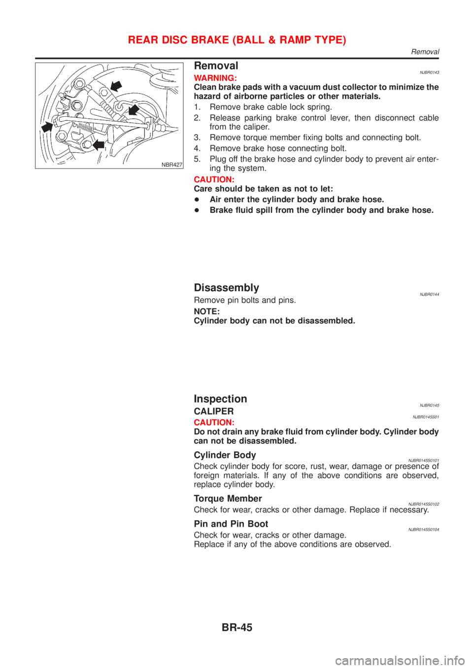
NBR427
RemovalNJBR0143WARNING:
Clean brake pads with a vacuum dust collector to minimize the
hazard of airborne particles or other materials.
1. Remove brake cable lock spring.
2. Release parking brake control lever, then disconnect cable
from the caliper.
3. Remove torque member fixing bolts and connecting bolt.
4. Remove brake hose connecting bolt.
5. Plug off the brake hose and cylinder body to prevent air enter-
ing the system.
CAUTION:
Care should be taken as not to let:
+Air enter the cylinder body and brake hose.
+Brake fluid spill from the cylinder body and brake hose.
DisassemblyNJBR0144Remove pin bolts and pins.
NOTE:
Cylinder body can not be disassembled.
InspectionNJBR0145CALIPERNJBR0145S01CAUTION:
Do not drain any brake fluid from cylinder body. Cylinder body
can not be disassembled.
Cylinder BodyNJBR0145S0101Check cylinder body for score, rust, wear, damage or presence of
foreign materials. If any of the above conditions are observed,
replace cylinder body.
Torque MemberNJBR0145S0102Check for wear, cracks or other damage. Replace if necessary.
Pin and Pin BootNJBR0145S0104Check for wear, cracks or other damage.
Replace if any of the above conditions are observed.
REAR DISC BRAKE (BALL & RAMP TYPE)
Removal
BR-45
Page 1744 of 2493

SBR219C
ROTORNJBR0145S02Rubbing SurfaceNJBR0145S0201Check rotor for roughness, cracks or chips.
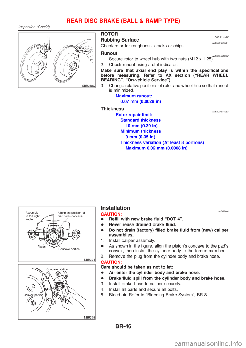
RunoutNJBR0145S02021. Secure rotor to wheel hub with two nuts (M12 x 1.25).
2. Check runout using a dial indicator.
Make sure that axial end play is within the specifications
before measuring. Refer to AX section (ªREAR WHEEL
BEARINGº, ªOn-vehicle Serviceº).
3. Change relative positions of rotor and wheel hub so that runout
is minimized.
Maximum runout:
0.07 mm (0.0028 in)
ThicknessNJBR0145S0203Rotor repair limit:
Standard thickness
10 mm (0.39 in)
Minimum thickness
9 mm (0.35 in)
Thickness variation (At least 8 portions)
Maximum 0.02 mm (0.0008 in)
NBR374
NBR375
InstallationNJBR0146CAUTION:
+Refill with new brake fluid ªDOT 4º.
+Never reuse drained brake fluid.
+Do not drain (factory) filled brake fluid from (new) caliper
assemblies.
1. Install caliper assembly.
+As shown in the figure, align the piston's concave to the pad's
convex, then install the cylinder body to the torque member.
2. Remove the plug from the cylinder body and brake hose.
CAUTION:
Care should be taken as not to let:
+Air enter the cylinder body and brake hose.
+Brake fluid spill from the cylinder body and brake hose.
3. Install brake hose to caliper securely.
4. Install all parts and secure all bolts.
5. Bleed air. Refer to ªBleeding Brake Systemº, BR-8.
REAR DISC BRAKE (BALL & RAMP TYPE)
Inspection (Cont'd)
BR-46
Page 1787 of 2493
ABS Actuator and Electric UnitNJBR0111S10
SBR630E
REMOVALNJBR0111S10011. Disconnect battery cable.
2. Drain brake fluid.
3. Remove mounting bracket fixing bolts and nuts.
4. Disconnect connector, brake pipes and remove fixing nuts.
INSTALLATIONNJBR0111S1002CAUTION:
After installation, refill brake fluid. Then bleed air.
1. Connect brake pipes temporarily.
2. Tighten fixing bolts and nuts.
3. Tighten brake pipes.
4. Connect connector and battery cable.
REMOVAL AND INSTALLATIONABS
ABS Actuator and Electric Unit
BR-89
Page 1807 of 2493

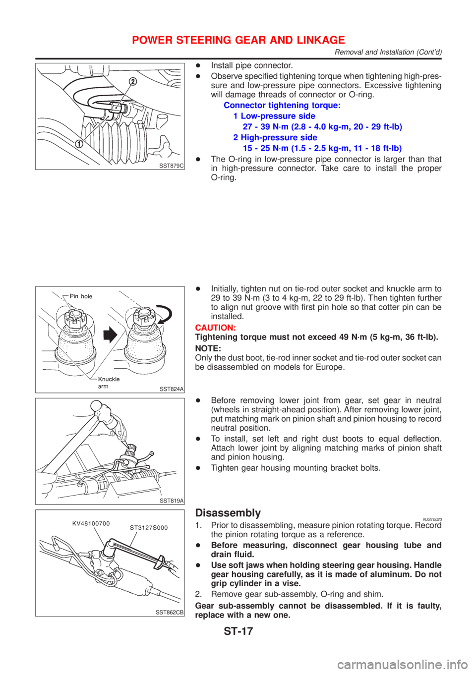
SST879C
+Install pipe connector.
+Observe specified tightening torque when tightening high-pres-
sure and low-pressure pipe connectors. Excessive tightening
will damage threads of connector or O-ring.
Connector tightening torque:
1 Low-pressure side
27 - 39 N´m (2.8 - 4.0 kg-m, 20 - 29 ft-lb)
2 High-pressure side
15 - 25 N´m (1.5 - 2.5 kg-m, 11 - 18 ft-lb)
+The O-ring in low-pressure pipe connector is larger than that
in high-pressure connector. Take care to install the proper
O-ring.
SST824A
+Initially, tighten nut on tie-rod outer socket and knuckle arm to
29 to 39 N´m (3 to 4 kg-m, 22 to 29 ft-lb). Then tighten further
to align nut groove with first pin hole so that cotter pin can be
installed.
CAUTION:
Tightening torque must not exceed 49 N´m (5 kg-m, 36 ft-lb).
NOTE:
Only the dust boot, tie-rod inner socket and tie-rod outer socket can
be disassembled on models for Europe.
SST819A
+Before removing lower joint from gear, set gear in neutral
(wheels in straight-ahead position). After removing lower joint,
put matching mark on pinion shaft and pinion housing to record
neutral position.
+To install, set left and right dust boots to equal deflection.
Attach lower joint by aligning matching marks of pinion shaft
and pinion housing.
+Tighten gear housing mounting bracket bolts.
SST862CB
DisassemblyNJST00231. Prior to disassembling, measure pinion rotating torque. Record
the pinion rotating torque as a reference.
+Before measuring, disconnect gear housing tube and
drain fluid.
+Use soft jaws when holding steering gear housing. Handle
gear housing carefully, as it is made of aluminum. Do not
grip cylinder in a vise.
2. Remove gear sub-assembly, O-ring and shim.
Gear sub-assembly cannot be disassembled. If it is faulty,
replace with a new one.
POWER STEERING GEAR AND LINKAGE
Removal and Installation (Cont'd)
ST-17