Page 1678 of 2493

SMA525A
On-vehicle Service
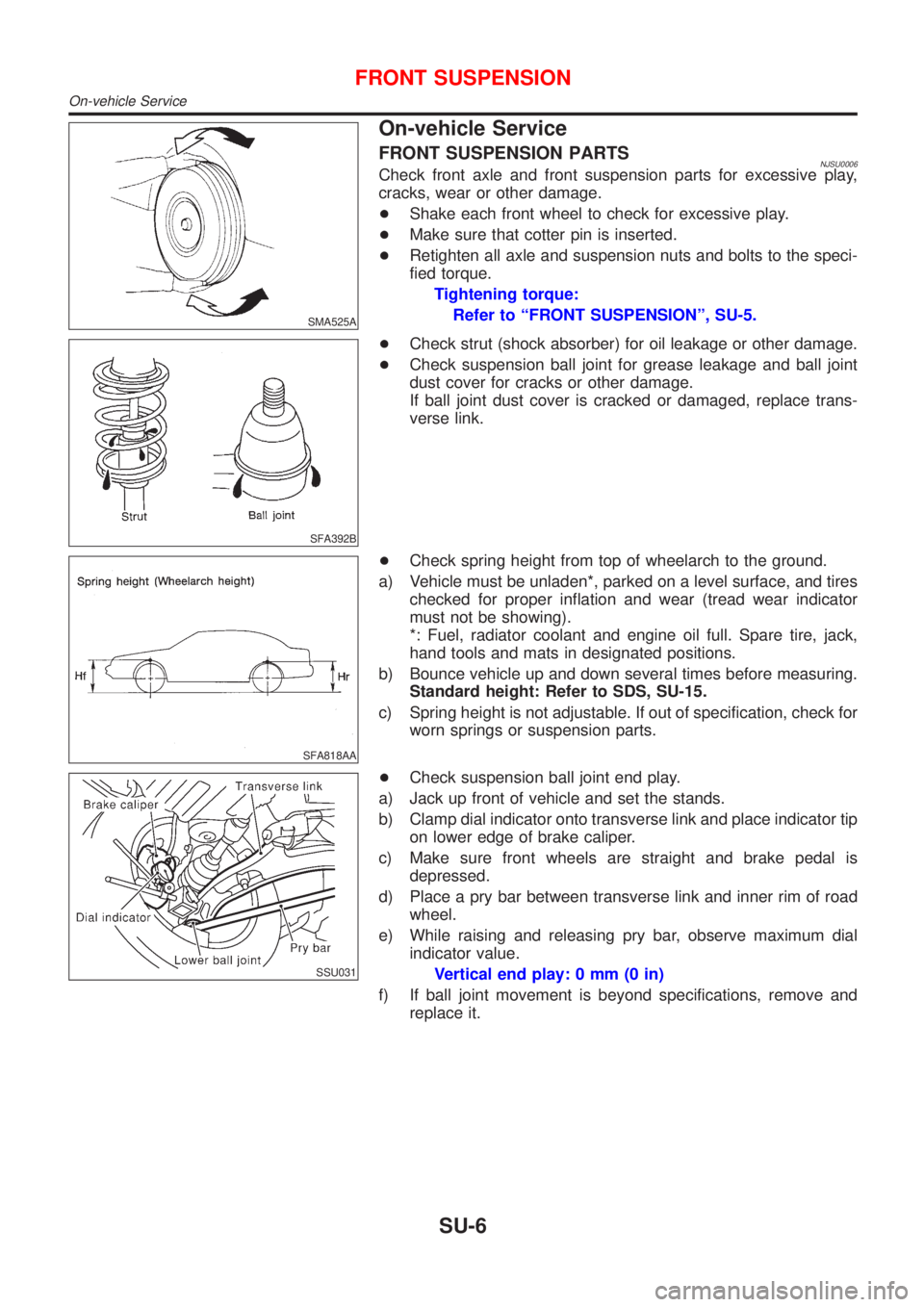
FRONT SUSPENSION PARTSNJSU0006Check front axle and front suspension parts for excessive play,
cracks, wear or other damage.
+Shake each front wheel to check for excessive play.
+Make sure that cotter pin is inserted.
+Retighten all axle and suspension nuts and bolts to the speci-
fied torque.
Tightening torque:
Refer to ªFRONT SUSPENSIONº, SU-5.
SFA392B
+Check strut (shock absorber) for oil leakage or other damage.
+Check suspension ball joint for grease leakage and ball joint
dust cover for cracks or other damage.
If ball joint dust cover is cracked or damaged, replace trans-
verse link.
SFA818AA
+Check spring height from top of wheelarch to the ground.
a) Vehicle must be unladen*, parked on a level surface, and tires
checked for proper inflation and wear (tread wear indicator
must not be showing).
*: Fuel, radiator coolant and engine oil full. Spare tire, jack,
hand tools and mats in designated positions.
b) Bounce vehicle up and down several times before measuring.
Standard height: Refer to SDS, SU-15.
c) Spring height is not adjustable. If out of specification, check for
worn springs or suspension parts.
SSU031
+Check suspension ball joint end play.
a) Jack up front of vehicle and set the stands.
b) Clamp dial indicator onto transverse link and place indicator tip
on lower edge of brake caliper.
c) Make sure front wheels are straight and brake pedal is
depressed.
d) Place a pry bar between transverse link and inner rim of road
wheel.
e) While raising and releasing pry bar, observe maximum dial
indicator value.
Vertical end play: 0 mm (0 in)
f) If ball joint movement is beyond specifications, remove and
replace it.
FRONT SUSPENSION
On-vehicle Service
SU-6
Page 2154 of 2493

SEL921W
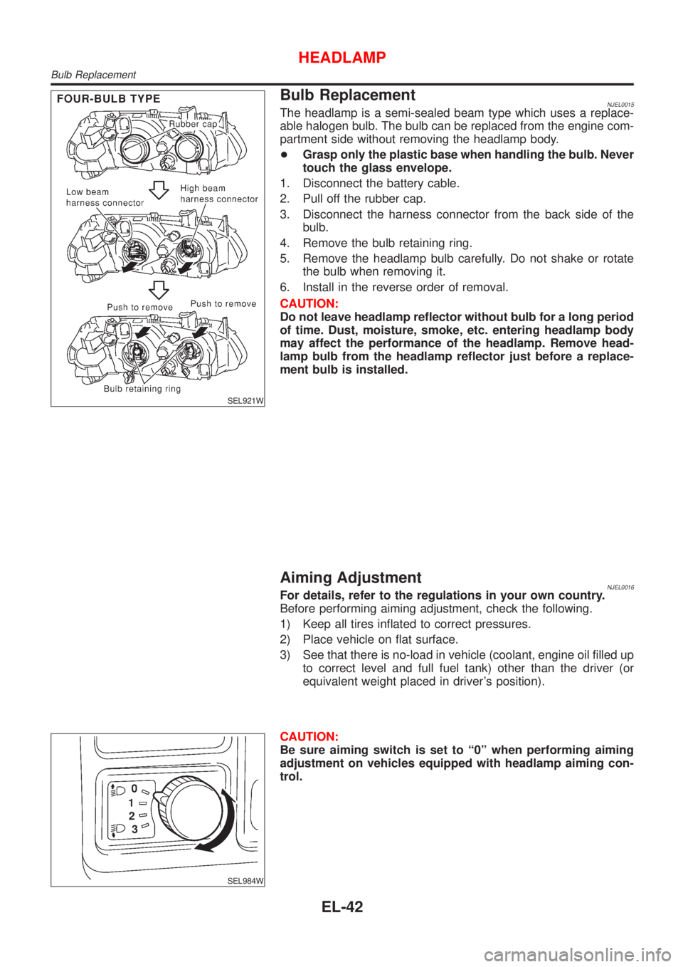
Bulb ReplacementNJEL0015The headlamp is a semi-sealed beam type which uses a replace-
able halogen bulb. The bulb can be replaced from the engine com-
partment side without removing the headlamp body.
+Grasp only the plastic base when handling the bulb. Never
touch the glass envelope.
1. Disconnect the battery cable.
2. Pull off the rubber cap.
3. Disconnect the harness connector from the back side of the
bulb.
4. Remove the bulb retaining ring.
5. Remove the headlamp bulb carefully. Do not shake or rotate
the bulb when removing it.
6. Install in the reverse order of removal.
CAUTION:
Do not leave headlamp reflector without bulb for a long period
of time. Dust, moisture, smoke, etc. entering headlamp body
may affect the performance of the headlamp. Remove head-
lamp bulb from the headlamp reflector just before a replace-
ment bulb is installed.
Aiming AdjustmentNJEL0016For details, refer to the regulations in your own country.
Before performing aiming adjustment, check the following.
1) Keep all tires inflated to correct pressures.
2) Place vehicle on flat surface.
3) See that there is no-load in vehicle (coolant, engine oil filled up
to correct level and full fuel tank) other than the driver (or
equivalent weight placed in driver's position).
SEL984W
CAUTION:
Be sure aiming switch is set to ª0º when performing aiming
adjustment on vehicles equipped with headlamp aiming con-
trol.
HEADLAMP
Bulb Replacement
EL-42
Page 2174 of 2493

SEL976W
SEL480X
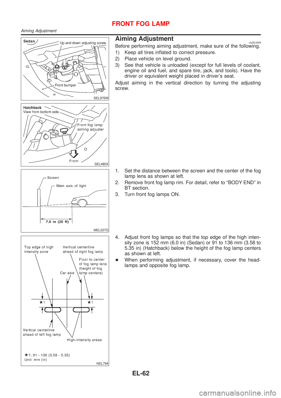
Aiming Adjustment=NJEL0029Before performing aiming adjustment, make sure of the following.
1) Keep all tires inflated to correct pressure.
2) Place vehicle on level ground.
3) See that vehicle is unloaded (except for full levels of coolant,
engine oil and fuel, and spare tire, jack, and tools). Have the
driver or equivalent weight placed in driver's seat.
Adjust aiming in the vertical direction by turning the adjusting
screw.
MEL327G
1. Set the distance between the screen and the center of the fog
lamp lens as shown at left.
2. Remove front fog lamp rim. For detail, refer to ªBODY ENDº in
BT section.
3. Turn front fog lamps ON.
NEL794
4. Adjust front fog lamps so that the top edge of the high inten-
sity zone is 152 mm (6.0 in) (Sedan) or 91 to 136 mm (3.58 to
5.35 in) (Hatchback) below the height of the fog lamp centers
as shown at left.
+When performing adjustment, if necessary, cover the head-
lamps and opposite fog lamp.
FRONT FOG LAMP
Aiming Adjustment
EL-62
Page 2202 of 2493

WATER TEMPERATURE GAUGENJEL0442S04The water temperature gauge indicates the engine coolant temperature. The reading on the gauge is based
on the resistance of the thermal transmitter.
As the temperature of the coolant increases, the resistance of the thermal transmitter decreases. A variable
ground is supplied to terminal 20 of the combination meter for the water temperature gauge. The needle on
the gauge moves from ªCº to ªHº.
TACHOMETERNJEL0442S05The tachometer indicates engine speed in revolutions per minute (rpm).
The tachometer is regulated by a signal
+from terminal 32 (Gasoline engine models) or 439 (Diesel engine models) of the ECM
+to combination meter terminal 22 for the tachometer.
FUEL GAUGENJEL0442S06The fuel gauge indicates the approximate fuel level in the fuel tank.
The fuel gauge is regulated by a variable ground signal supplied
+from body grounds M28 and M67
+through terminals 9 and 10 of combination meter,
+through terminal 1 of the fuel level sensor unit and
+through terminal 4 of the fuel level sensor unit
+to combination meter terminal 24 for the fuel gauge.
SPEEDOMETERNJEL0442S07The combination meter provides a voltage signal to the vehicle speed sensor for the speedometer.
The voltage is supplied
+from combination meter terminal 5 for the speedometer
+to terminal 1 of the vehicle speed sensor.
Ground is supplied
+from body grounds M28 and M67
+through terminals 10 and 11 of combination meter
+to teminal 2 of the vehicle speed sensor.
The speedometer converts the voltage into the vehicle speed displayed.
METERS AND GAUGES
System Description (Cont'd)
EL-90
Page:
< prev 1-8 9-16 17-24