2001 NISSAN ALMERA N16 check oil
[x] Cancel search: check oilPage 2075 of 2493
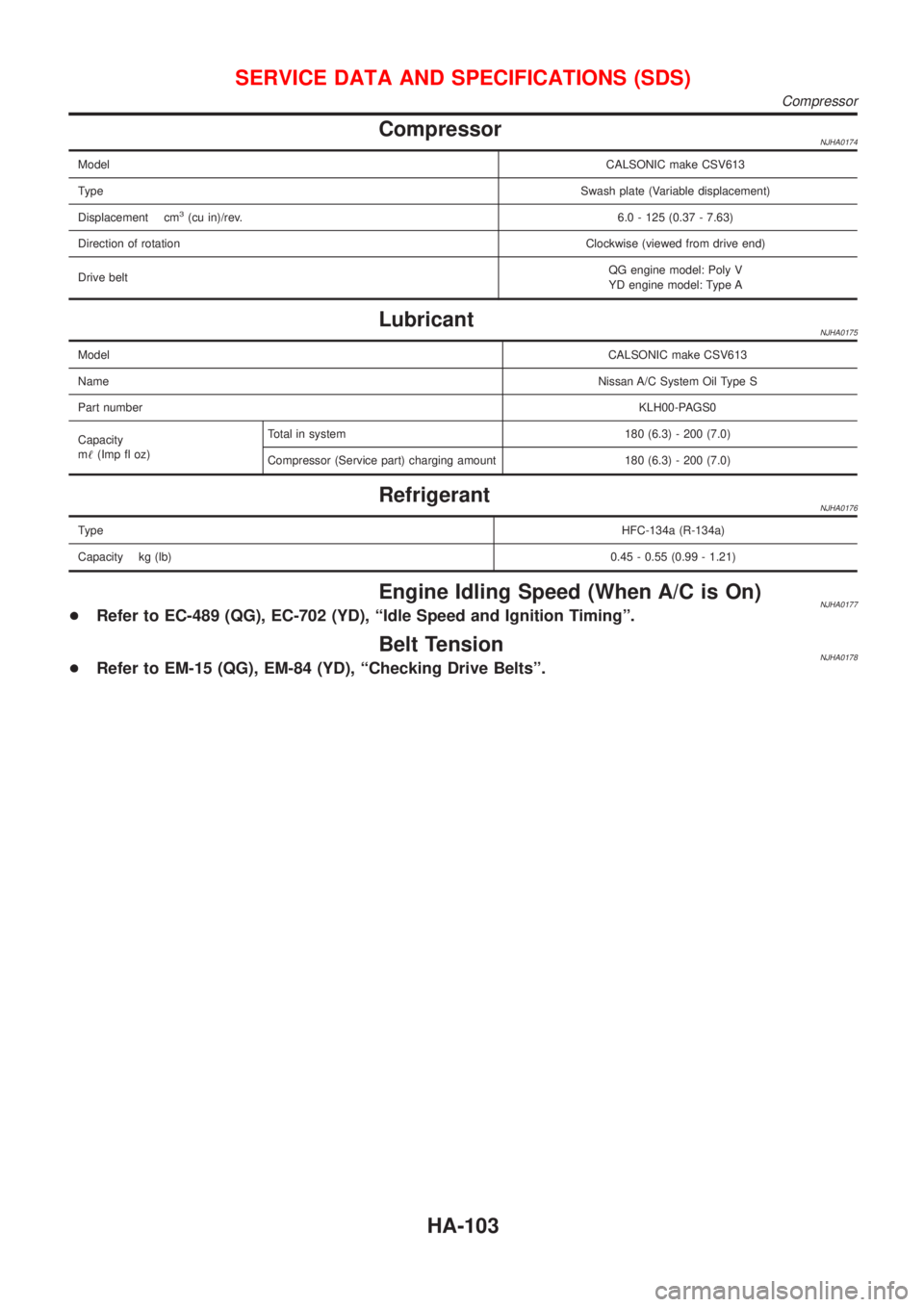
CompressorNJHA0174
ModelCALSONIC make CSV613
TypeSwash plate (Variable displacement)
Displacement cm
3(cu in)/rev.6.0 - 125 (0.37 - 7.63)
Direction of rotationClockwise (viewed from drive end)
Drive beltQG engine model: Poly V
YD engine model: Type A
LubricantNJHA0175
ModelCALSONIC make CSV613
NameNissan A/C System Oil Type S
Part numberKLH00-PAGS0
Capacity
m!(Imp fl oz)Total in system 180 (6.3) - 200 (7.0)
Compressor (Service part) charging amount 180 (6.3) - 200 (7.0)
RefrigerantNJHA0176
TypeHFC-134a (R-134a)
Capacity kg (lb)0.45 - 0.55 (0.99 - 1.21)
Engine Idling Speed (When A/C is On)NJHA0177+Refer to EC-489 (QG), EC-702 (YD), ªIdle Speed and Ignition Timingº.
Belt TensionNJHA0178+Refer to EM-15 (QG), EM-84 (YD), ªChecking Drive Beltsº.
SERVICE DATA AND SPECIFICATIONS (SDS)
Compressor
HA-103
Page 2102 of 2493
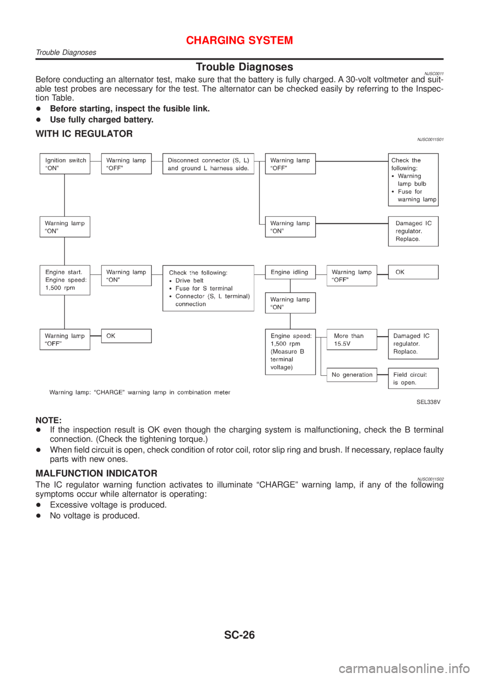
Trouble DiagnosesNJSC0011Before conducting an alternator test, make sure that the battery is fully charged. A 30-volt voltmeter and suit-
able test probes are necessary for the test. The alternator can be checked easily by referring to the Inspec-
tion Table.
+Before starting, inspect the fusible link.
+Use fully charged battery.
WITH IC REGULATORNJSC0011S01
SEL338V
NOTE:
+If the inspection result is OK even though the charging system is malfunctioning, check the B terminal
connection. (Check the tightening torque.)
+When field circuit is open, check condition of rotor coil, rotor slip ring and brush. If necessary, replace faulty
parts with new ones.
MALFUNCTION INDICATORNJSC0011S02The IC regulator warning function activates to illuminate ªCHARGEº warning lamp, if any of the following
symptoms occur while alternator is operating:
+Excessive voltage is produced.
+No voltage is produced.
CHARGING SYSTEM
Trouble Diagnoses
SC-26
Page 2154 of 2493
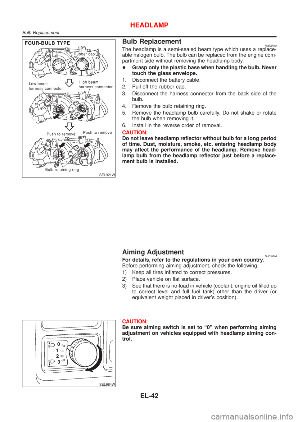
SEL921W
Bulb ReplacementNJEL0015The headlamp is a semi-sealed beam type which uses a replace-
able halogen bulb. The bulb can be replaced from the engine com-
partment side without removing the headlamp body.
+Grasp only the plastic base when handling the bulb. Never
touch the glass envelope.
1. Disconnect the battery cable.
2. Pull off the rubber cap.
3. Disconnect the harness connector from the back side of the
bulb.
4. Remove the bulb retaining ring.
5. Remove the headlamp bulb carefully. Do not shake or rotate
the bulb when removing it.
6. Install in the reverse order of removal.
CAUTION:
Do not leave headlamp reflector without bulb for a long period
of time. Dust, moisture, smoke, etc. entering headlamp body
may affect the performance of the headlamp. Remove head-
lamp bulb from the headlamp reflector just before a replace-
ment bulb is installed.
Aiming AdjustmentNJEL0016For details, refer to the regulations in your own country.
Before performing aiming adjustment, check the following.
1) Keep all tires inflated to correct pressures.
2) Place vehicle on flat surface.
3) See that there is no-load in vehicle (coolant, engine oil filled up
to correct level and full fuel tank) other than the driver (or
equivalent weight placed in driver's position).
SEL984W
CAUTION:
Be sure aiming switch is set to ª0º when performing aiming
adjustment on vehicles equipped with headlamp aiming con-
trol.
HEADLAMP
Bulb Replacement
EL-42
Page 2224 of 2493
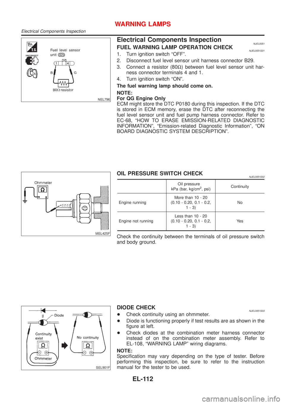
NEL796
Electrical Components InspectionNJEL0051FUEL WARNING LAMP OPERATION CHECKNJEL0051S011. Turn ignition switch ªOFFº.
2. Disconnect fuel level sensor unit harness connector B29.
3. Connect a resistor (80W) between fuel level sensor unit har-
ness connector terminals 4 and 1.
4. Turn ignition switch ªONº.
The fuel warning lamp should come on.
NOTE:
For QG Engine Only
ECM might store the DTC P0180 during this inspection. If the DTC
is stored in ECM memory, erase the DTC after reconnecting the
fuel level sensor unit and fuel pump harness connector. Refer to
EC-68, ªHOW TO ERASE EMISSION-RELATED DIAGNOSTIC
INFORMATIONº, ªEmission-related Diagnostic Informationº, ªON
BOARD DIAGNOSTIC SYSTEM DESCRIPTIONº.
MEL425F
OIL PRESSURE SWITCH CHECKNJEL0051S02
Oil pressure
kPa (bar, kg/cm2, psi)Continuity
Engine runningMore than 10 - 20
(0.10 - 0.20, 0.1 - 0.2,
1-3)No
Engine not runningLess than 10 - 20
(0.10 - 0.20, 0.1 - 0.2,
1-3)Ye s
Check the continuity between the terminals of oil pressure switch
and body ground.
SEL901F
DIODE CHECKNJEL0051S03+Check continuity using an ohmmeter.
+Diode is functioning properly if test results are as shown in the
figure at left.
+Check diodes at the combination meter harness connector
instead of on the combination meter assembly. Refer to
EL-108, ªWARNING LAMPº wiring diagrams.
NOTE:
Specification may vary depending on the type of tester. Before
performing this inspection, be sure to refer to the instruction
manual for the tester to be used.
WARNING LAMPS
Electrical Components Inspection
EL-112
Page 2255 of 2493
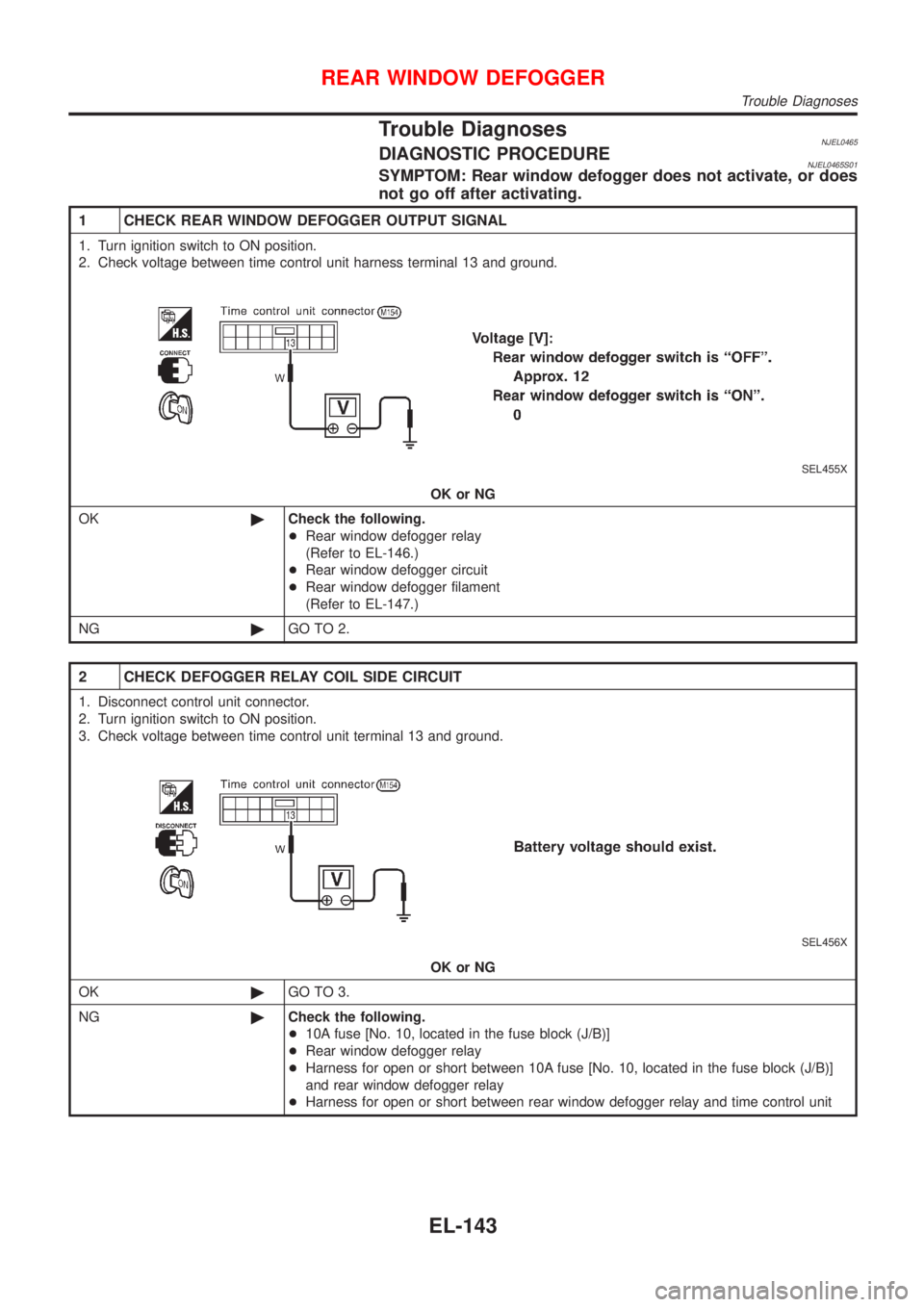
Trouble DiagnosesNJEL0465DIAGNOSTIC PROCEDURENJEL0465S01SYMPTOM: Rear window defogger does not activate, or does
not go off after activating.
1 CHECK REAR WINDOW DEFOGGER OUTPUT SIGNAL
1. Turn ignition switch to ON position.
2. Check voltage between time control unit harness terminal 13 and ground.
SEL455X
OK or NG
OK©Check the following.
+Rear window defogger relay
(Refer to EL-146.)
+Rear window defogger circuit
+Rear window defogger filament
(Refer to EL-147.)
NG©GO TO 2.
2 CHECK DEFOGGER RELAY COIL SIDE CIRCUIT
1. Disconnect control unit connector.
2. Turn ignition switch to ON position.
3. Check voltage between time control unit terminal 13 and ground.
SEL456X
OK or NG
OK©GO TO 3.
NG©Check the following.
+10A fuse [No. 10, located in the fuse block (J/B)]
+Rear window defogger relay
+Harness for open or short between 10A fuse [No. 10, located in the fuse block (J/B)]
and rear window defogger relay
+Harness for open or short between rear window defogger relay and time control unit
REAR WINDOW DEFOGGER
Trouble Diagnoses
EL-143
Page 2259 of 2493
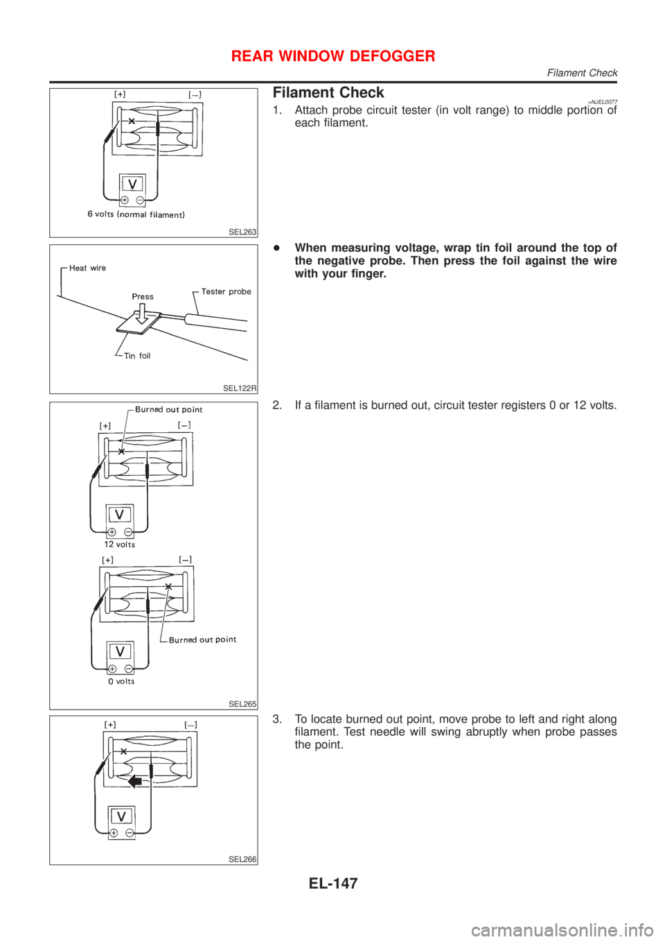
SEL263
Filament Check=NJEL00771. Attach probe circuit tester (in volt range) to middle portion of
each filament.
SEL122R
+When measuring voltage, wrap tin foil around the top of
the negative probe. Then press the foil against the wire
with your finger.
SEL265
2. If a filament is burned out, circuit tester registers 0 or 12 volts.
SEL266
3. To locate burned out point, move probe to left and right along
filament. Test needle will swing abruptly when probe passes
the point.
REAR WINDOW DEFOGGER
Filament Check
EL-147
Page 2272 of 2493
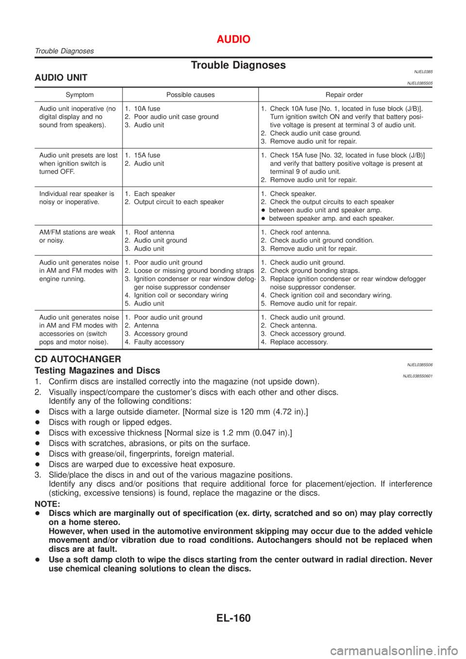
Trouble DiagnosesNJEL0385AUDIO UNITNJEL0385S05
Symptom Possible causes Repair order
Audio unit inoperative (no
digital display and no
sound from speakers).1. 10A fuse
2. Poor audio unit case ground
3. Audio unit1. Check 10A fuse [No. 1, located in fuse block (J/B)].
Turn ignition switch ON and verify that battery posi-
tive voltage is present at terminal 3 of audio unit.
2. Check audio unit case ground.
3. Remove audio unit for repair.
Audio unit presets are lost
when ignition switch is
turned OFF.1. 15A fuse
2. Audio unit1. Check 15A fuse [No. 32, located in fuse block (J/B)]
and verify that battery positive voltage is present at
terminal 9 of audio unit.
2. Remove audio unit for repair.
Individual rear speaker is
noisy or inoperative.1. Each speaker
2. Output circuit to each speaker1. Check speaker.
2. Check the output circuits to each speaker
+between audio unit and speaker amp.
+between speaker amp. and each speaker.
AM/FM stations are weak
or noisy.1. Roof antenna
2. Audio unit ground
3. Audio unit1. Check roof antenna.
2. Check audio unit ground condition.
3. Remove audio unit for repair.
Audio unit generates noise
in AM and FM modes with
engine running.1. Poor audio unit ground
2. Loose or missing ground bonding straps
3. Ignition condenser or rear window defog-
ger noise suppressor condenser
4. Ignition coil or secondary wiring
5. Audio unit1. Check audio unit ground.
2. Check ground bonding straps.
3. Replace ignition condenser or rear window defogger
noise suppressor condenser.
4. Check ignition coil and secondary wiring.
5. Remove audio unit for repair.
Audio unit generates noise
in AM and FM modes with
accessories on (switch
pops and motor noise).1. Poor audio unit ground
2. Antenna
3. Accessory ground
4. Faulty accessory1. Check audio unit ground.
2. Check antenna.
3. Check accessory ground.
4. Replace accessory.
CD AUTOCHANGERNJEL0385S06Testing Magazines and DiscsNJEL0385S06011. Confirm discs are installed correctly into the magazine (not upside down).
2. Visually inspect/compare the customer's discs with each other and other discs.
Identify any of the following conditions:
+Discs with a large outside diameter. [Normal size is 120 mm (4.72 in).]
+Discs with rough or lipped edges.
+Discs with excessive thickness [Normal size is 1.2 mm (0.047 in).]
+Discs with scratches, abrasions, or pits on the surface.
+Discs with grease/oil, fingerprints, foreign material.
+Discs are warped due to excessive heat exposure.
3. Slide/place the discs in and out of the various magazine positions.
Identify any discs and/or positions that require additional force for placement/ejection. If interference
(sticking, excessive tensions) is found, replace the magazine or the discs.
NOTE:
+Discs which are marginally out of specification (ex. dirty, scratched and so on) may play correctly
on a home stereo.
However, when used in the automotive environment skipping may occur due to the added vehicle
movement and/or vibration due to road conditions. Autochangers should not be replaced when
discs are at fault.
+Use a soft damp cloth to wipe the discs starting from the center outward in radial direction. Never
use chemical cleaning solutions to clean the discs.
AUDIO
Trouble Diagnoses
EL-160
Page 2482 of 2493
A
A/C HFC134a (R134a) system precaution . HA-2
A/C HFC134a (R134a) system service
procedure .............................................. HA-84
A/C HFC134a (R134a) system service
tools ....................................................... HA-11
A/C HFC134a system service equip-
ment precaution ....................................... HA-6
A/C air flow ............................................... HA-20
A/C component layout .............................. HA-18
A/C compressor clutch removal and
installation .............................................. HA-89
A/C compressor precaution ........................ HA-5
A/C compressor special service tool .......... HA-9
A/C control linkage adjustment
(manual A/C) ......................................... HA-47
A/C control operation (manual A/C) .......... HA-19
A/C diagnostic work flow
(manual A/C) ......................................... HA-39
A/C harness layout (manual A/C) ............. HA-22
A/C lubricant (R134a) ............................... HA-86
A/C operational check ............................... HA-40
A/C performance chart .............................. HA-77
A/C performance test diagnoses .............. HA-75
A/C relay ................................................... HA-72
A/C service data specification ................ HA-103
A/C switch ................................................. HA-73
A/C, M - Wiring diagram ........................... HA-27
A/CCUT - Wiring diagram ....................... EC-700
A/T - Wiring diagram - AT - 1ST .............. AT-205
A/T - Wiring diagram - AT - 2ND ............. AT-212
A/T - Wiring diagram - AT - 3RD ............. AT-218
A/T - Wiring diagram - AT - 4TH .............. AT-225
A/T - Wiring diagram - AT - BA/FTS ....... AT-165,
273
A/T - Wiring diagram - AT - ENG SS ...... AT-171,
199
A/T - Wiring diagram - AT - FTS .............. AT-189
A/T - Wiring diagram - AT - LPSV ... AT-176, 239
A/T - Wiring diagram - AT - MAIN ........... AT-121
A/T - Wiring diagram - AT -
OVRCSV ...................................... AT-153, 267
A/T - Wiring diagram - AT - PNP/SW ...... AT-183
A/T - Wiring diagram - AT - SSV/A .. AT-142, 246
A/T - Wiring diagram - AT - SSV/B .. AT-148, 252
A/T - Wiring diagram - AT - TCV ..... AT-159, 233
A/T - Wiring diagram - AT - TPS ..... AT-134, 259
A/T - Wiring diagram - AT - VSS/AT ....... AT-126,
195
A/T - Wiring diagram - AT -
VSSMTR ...................................... AT-130, 280
A/T control ............................................... EC-437
A/T diagnosis communication line .......... EC-361
A/T fluid temperature sensor ................... AT-192
A/T shift lock system - Wiring
diagram ................................................ AT-336
A/T shift lock system ................................ AT-335
A/T trouble diagnoses .......................... AT-67, 72AAC/V - Wiring diagram ................. EC-315, 420
ABS (anti-lock brake system) ................... BR-49
ABS - Wiring diagram ............................... BR-54
ABS sensor rotor ....................................... AX-24
APS - Wiring diagram ............................. EC-577
ATDIAG - Wiring diagram ............... EC-362, 438
Accelerator control system .................... FE-3, 15
Accelerator position sensor .................... EC-577
Air bag disposal ........................................ RS-35
Air bag precautions ...................................... GI-3
Air bag ....................................................... RS-20
Air bleeding (hydraulic clutch) ................... CL-10
Air bleeding for brake system ..................... BR-8
Air conditioner cut control ................. EC-32, 507
Air flow meter - See Mass air flow
sensor .......................................... EC-152, 566
Air mix door control linkage
adjustment ............................................. HA-49
Air spoiler, rear .......................................... BT-47
Alternator ................................................... SC-27
Angular tightening application .............. EM-4, 76
Antenna - See Power antenna ................ EL-162
Anti-lock brake system - Wiring
diagram .................................................. BR-54
Audio and A/C control removal and
installation - See Instrument panel ........ BT-25
Audio ........................................................ EL-149
Automatic transaxle number ...................... GI-41
Auxiliary air control (AAC) valve ..... EC-313, 418
B
Back-up lamp switch (M/T) ....................... MT-21
Back-up lamp ............................................. EL-58
Ball joint (front) .......................................... SU-13
Basic inspection ................................ EC-98, 536
Battery ......................................................... SC-3
Baulk ring (M/T) ............................ MT-31, 55, 93
Blower motor ............................................. HA-60
Blower resistor .......................................... HA-60
Board-on lift ................................................ GI-44
Body alignment .......................................... BT-74
Brake booster ............................................ BR-20
Brake fluid change ...................................... BR-7
Brake fluid level and line check .................. BR-7
Brake hydraulic line .................................... BR-9
Brake pedal ............................................... BR-12
Bulb specifications ................................... EL-366
Bumper, front .............................................. BT-7
Bumper, rear .............................................. BT-10
C
CHARGE - Wiring diagram ....................... SC-25
CHIME - Wiring diagram .......................... EL-115
CIGAR - Wiring diagram ......................... EL-136
CKPS - Wiring diagram .......... EC-274, 395, 587
CMPS - Wiring diagram .......................... EC-280
ALPHABETICAL INDEX
IDX-2